Table of Contents
Advertisement
Advertisement
Table of Contents

Subscribe to Our Youtube Channel
Related Manuals for Neolt STRONG trim pro 130

Summary of Contents for Neolt STRONG trim pro 130
- Page 2 STRONG trim pro 130 / 1800 / 230 USER’S MANUAL NEOLT Cod. NLT.QR-C-N-MM-2-1S-GB ENGLISH 2002 USOGB-STR_pro.DOC...
-
Page 3: Table Of Contents
CONTENTS NEOLT SECTOR: DATE: STRONG TRIM PRO 19/03/2002 VERSION: AUTHOR: STR_PRO-01 POLENI P. Chapter General Information ................... 1 1.1 Data of the manual ................1-1 1.2 Users ....................1-1 1.3 Property of information................1-1 1.4 Conventions..................1-2 1.4.1 Conventional terms ..............1-2 1.4.2 Conventional symbols used ............ - Page 4 CONTENTS NEOLT Chapter Use ......................5 5.1 Qualification of the operator..............5-1 5.1.1 Working place ................5-1 5.1.2 Insertion of the media to be cut ........... 5-1 5.1.3 Characteristics of the media to be cut ......... 5-2 Chapter Maintenance ....................6 6.1 Routine maintenance................
-
Page 5: General Information
NEOLT S.p.A. These documents are provided only for the use of the client whom the manual has been supplied to with the machine, and can be used only for the installation, use and maintenance of the machine the manual refers to. -
Page 6: Conventions
GENERAL INFORMATION NEOLT Conventions Conventional terms 1.4.1 Machine: indicates the machine specified in section 1.6 Identification data of the machine. Frame: structure supporting the machine. Qualified personnel: people, who thanks to their qualification, preparation and experience, and thanks to the knowledge of the relevant rules, safety requirements and service norms, are able to recognize and avoid any possible danger for the people, the material and the machine. -
Page 7: Identification Data Of The Manufacturer
GENERAL INFORMATION NEOLT Identification data of the manufacturer neolt S.p.A. Via G. Galilei, 8 24036 Ponte San Pietro (BG) - ITALY Tel. 035/468811 Fax 035/468886 http://www.neolt.it E-mail.: mkt@neolt.it Identification data of the machine Name TRIMMER STrONG TRIM Model Serial number... -
Page 8: Warranty
In no case can the purchaser demand the resolution of the contract, claim for damages or the extension of the warranty. NEOLT S.p.A. cannot be held responsible for any negative advertisement, or loss of earnings, due to technical or mechanical malfunctioning of the product in use or in display. -
Page 9: Description Of The Machine
GENERAL INFORMATION NEOLT Description of the machine 1.10 Correct use of the machine 1.10.1 This machine can be used only to cut media having the allowed basic weight (max paper thickness 4,5 mm). As the machine consists of assemblies physically separated and autonomous, the proper use of the machine can be identified also in the operation of a single part. -
Page 10: Structure Of The Machine
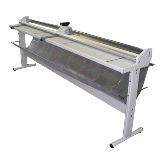
GENERAL INFORMATION NEOLT Structure of the machine 1.10.3 Fig. 1.1 Prospect views The machine is composed of the following parts: Work surface Support Paper collecting drape Brackets Blade holder carriage Sliding bar Fig. 1. 2 Detail Fig. 1. 3 Prospect views... -
Page 11: Safety Criteria
This also refers to the use of the protection devices foreseen, both those integrated in the machine and personal. NEOLT S.p.A. cannot be held responsible for any damages to people, pets or objects due to noncompliance with the safety rules and the recommendations contained in the supplied documentation. -
Page 12: Protections
Demolition Qualified personnel Protections NEOLT S.p.A. cannot be held responsible for any damages to people, pets or objects due to noncompliance with the safety rules and the recommendations contained in the supplied documentation. Tampering with the protections and the safety devices is dangerous for the people using the machine and for those exposed to it. -
Page 13: Dangerous Areas And Residual Risks
Pay attention to the warning labels applied to the trimmer NEOLT S.p.A. cannot be held responsible for any damages to people, pets or objects due to noncompliance with the rules or if the prescribed individual protection equipment is not used (IPE). - Page 14 INFORMATION ON NEOLT SAFETY STRONG trim PRO...
-
Page 15: Characteristics Of The Machine
CHARACTERISTICS OF NEOLT THE MACHINE Technical specifications MODEL Max. cutting thickness (mm) Usable cutting length (cm) Length (cm) Width (cm) Height (with holder) (cm) Height of working table (cm) Trim weight (kg) Support weight (kg) Reel holder Accessories Cutting area lamp... - Page 16 CHARACTERISTICS OF NEOLT THE MACHINE List of material strong TRIM pro Max. cutting thickness Material 4,5mm Drawing paper Board Cibachrome Slides Acrylic film Hard board Hot seal film Lead Leather Lithoplate Magnetic vinyl Carton Paper Photographic film Photographic paper Polypropylene film...
-
Page 17: Installation
INSTALLATION NEOLT Qualification of the operator Transport, installation and connection operations must be performed only by personnel qualified in transportation and electrical operations. Transport Transport conditions 4.2.1 The trimmer is shipped with a packaging consisting of three cardboards components protection, and of a carton box containing all the components. -
Page 18: Assessment Of Damages During Transportation
INSTALLATION NEOLT Fig. 4.1 Transport conditions Assessment of damages during transportation 4.2.2 Check the conditions of the machine by visually inspecting it, after having removed it from the shipping box. Any defects on the visible parts of the machine indicate crashes during transportation, which could also affect the ordinary operation of the machine. -
Page 19: Assembling
Attention When you assemble the upper traverse, the central push rod must face upwards . The value set by Neolt is 3 mm. STRONG trim PRO... - Page 20 INSTALLATION NEOLT To assemble the paper collection basket, first slide in the front (lower) and then the back (high) basket holding rods, and block them in the shoulder with two Benzing rings per rod , in the proper seats on the rod.
- Page 21 INSTALLATION NEOLT As the trimmer is vary heavy, wear proper working gloves, and remember that for this operation minimum four persons are required. • Place the trimmer on the assembled support securing it on the support itself with the provided screws (2 on each side) During this operation move the feeding table of the trimmer to make fixing operations to the stand easier.
-
Page 22: Adjustment
INSTALLATION NEOLT Adjustment The trimmer should not need any specific adjustments, but we do suggest to check the two options that could be slightly different, due to the final positioning of the trimmer. Planarity The first adjustment is the planarity of the working table, which could vary due to unleveled floors. -
Page 23: Storage
INSTALLATION NEOLT Storage The instructions contained in this section should be respected during temporary storage periods, which could occur in the following situations: • Installation of the machine delayed with respect of the delivery date. • Deactivation of the machine and consequent storage while waiting for a new installation. -
Page 24: Testing
• Allowed relative humidity: from 30 % to 80 %. Testing 4.6.2 Before attempting the normal and continuous operation of the machine, check its appropriate general operation by performing some test cuts. In case of malfunctioning, find cause and/or call NEOLT technical service. STRONG trim PRO... -
Page 25: Use
NEOLT Qualification of the operator The machine must be used by qualified personnel only. Workplace 5.1.1 Position of the operator: During start up and cutting, operator’s positing is in front of the machine, with the control panel in the centre. In case of maintenance, his position depends on the operation to be performed. -
Page 26: Characteristics Of The Media To Be Cut
NEOLT For media with thickness from 2mm. up to max 4,5 mm. Follow this procedure to cut media with thickness higher than 2mm until you reach a maximum of 4,5mm: • Position the media to cut on the feeding table and use the brackets to block the media so it doesn’t slide... -
Page 27: Maintenance
MAINTENANCE NEOLT Routine maintenance Untimely movements during maintenance. Be very careful. Routine maintenance includes all the periodic and preventive operations enabling a safe use of the machine. Qualification of the operator 6.1.1 Routine maintenance must be carried put only by qualified personnel. - Page 28 MAINTENANCE NEOLT STRONG trim PRO...
-
Page 29: Qualification Of The Operator
However, it must allow the reuse of the raw materials which it was built with. NEOLT S.p.A. cannot be held responsible for damages to people or pets due to the reutilization of single parts of the machine for purposes or in situations different from those which it has been designed for. - Page 30 DISMALTING NEOLT STRONG trim PRO...
-
Page 31: Attachment 1
ATTACHMENTS NEOLT Attachment 1 Assembly optional – reel holder Attachment 2 Assembly optional – sheet holder bar Attachment 3 Assembly optional – cutting area lamp Attachment 4 Technical sheet – replacement of rotating blade Attachment 5 Part-list – and drawing... - Page 32 ATTACHMENTS NEOLT STRONG trim PRO...
-
Page 33: Optional Reel Holder
OPTIONAL NEOLT REEL HOLDER Assembly of optional roll holder Follow this procedure assemble the reel holder: • Insert the reel holder supports in the right and left legs screw on the proper screw in the back part of the stand •... -
Page 34: Assembly Of Optional Reel Holder
OPTIONAL NEOLT REEL HOLDER STRONG trim PRO... -
Page 35: Optional Sheet-Holder Bar
OPTIONAL NEOLT SHEET-HOLDER BAR Assembly of optional sheet-holder bar Follow this procedure to assemble the optional sheet-holder bar: • Remove the components of the Fig. 1 sheet holder from the box. The assembly components (Fig. 1) and the bar (Fig. 2). - Page 36 OPTIONAL NEOLT SHEET-HOLDER BAR • Slide in the spring of the sheet holder (Fig. 6) and the sheet holder bar (Fig. 7). Fig. 6 Fig. 7 • Insert the blocking handle in the top Fig. 8 part: the smooth part outwards, the crowned part inwards.
-
Page 37: Feeding The Media To Cut
OPTIONAL NEOLT SHEET-HOLDER BAR • Follow the same operation on the opposite side. Feeding the media to cut Follow the procedure of the manual in paragraph 5.1.2 to trim the media with the sheet holder bar. After inserting the media to trim, block it with the sheet holder bar, rotating the two side handles of the bar downwards. - Page 38 OPTIONAL NEOLT SHEET-HOLDER BAR STRONG trim PRO...
-
Page 39: Assembly Of Lamp - Optional
OPTIONAL NEOLT CUTTING AREA LAMP Assembly of the lamp - optional To assemble the lamp in the cutting area, follow this procedure: • Remove lamp from the box and the bag with the supplied screws. • Remove lamp from lamp holders (Fig. 1). - Page 40 OPTIONAL NEOLT CUTTING AREA LAMP • Slide lamp out of protection carton and insert it in the lamp holder on the glass ceiling lamp. (Fig. 4). • Plug the electric wire and switch lamp on or off using the through switch on the cable (Fig.
-
Page 41: Technical Sheet
TECHNICAL SHEET NEOLT REPLACEMENT OF ROTATING BLADES Replacing rotating blades Follow this procedure to replace the blades, or the rotating blades: • Remove the screws that fix the panel of the presser and remove it • Remove the screws that fix the presser plate and remove it •... - Page 42 TECHNICAL SHEET NEOLT REPLACEMENT OF ROTATING BLADES • Push the front carriage towards the left to slide it out of its seat • Put the front part on a table, slightly move the blade and remove the Benzing ring from its seat, slide out the pin to replace the rotating blade •...
- Page 44 NEOLT S.p.A Via G. Galilei 8 24036 Ponte San Pietro (BG) – ITALY 035/468811 035/468886 NEOLT 2002...
Need help?
Do you have a question about the STRONG trim pro 130 and is the answer not in the manual?
Questions and answers