
Summary of Contents for AURES POSEO 5100
- Page 1 User Manual April 2010 Revision 1.1 POSEO 5100 POSEO 5100 POSEO 5100 POSEO 5100 Hardware System Hardware System Hardware System Hardware System...
- Page 2 Copyright 2008~2010 All Rights Reserved Manual Version 1.1 The information contained in this document is subject to change without notice. We make no warranty of any kind with regard to this material, including, but not limited to, the implied warranties of merchantability and fitness for a particular purpose. We shall not be liable for errors contained herein or for incidental or consequential damages in connection with the furnishing, performance, or use of this material.
-
Page 3: Important Safety Instructions
Safety IMPORTANT SAFETY INSTRUCTIONS 1. To disconnect the machine from the electrial power supply, turn off the power switch and remove the power cord plug from the wall socket. The wall socket must be easily accessible and in close proximity to the machine. 2. - Page 4 CAUTION ON LITHIUM BATTERIES There is a danger of explosion if the battery is replaced incorrectly. Replace only with the same or equivalent type recommended by the manufacturer. Discard used batteries according to the manufacturer’s instructions. LEGISLATION AND WEEE SYMBOL 2002/96/EC Waste Electrical and Electronic Equipment Directive on the treatment, collection, recycling and disposal of electric and electronic devices and their components.
- Page 5 Revision History Revision Description Revision Date Number Initial release May 2008 Updated specification table Added Appendix B: Dimensional April 2010 drawings...
-
Page 6: Table Of Contents
Table of Content 1. Packing List........................8 2. System View ........................9 2.1 Front View......................9 2.2 I/O View ......................10 3. Driver Installation ......................11 3.1 Driver List......................11 3.2 Chipset Driver Installation ................... 11 3.3 USB 2.0 Driver Installation OS Requirements............. 13 3.4 VGA IEGD Driver Installation ................ -
Page 8: Packing List
1. Packing List Take the system unit out of the carton. Remove the unit from the carton by holding it by the foam inserts. The following contents should be found in the carton: a. Power Cable b. Driver CD... -
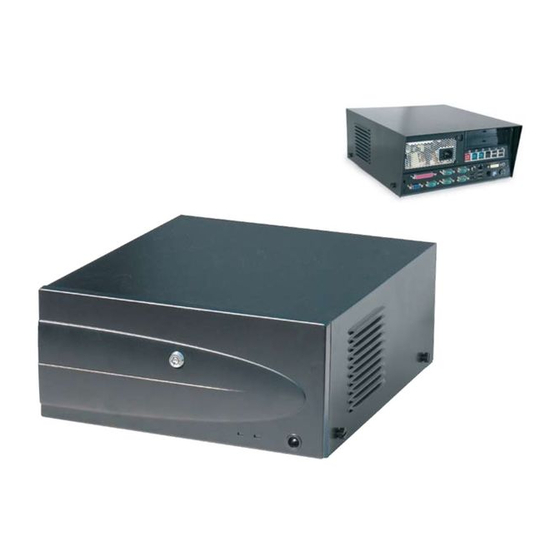
Page 9: System View
2. System View 2.1 Front View 1 x USB behind Key Lock Battery Power Power Button front bezel (See Ch. 5.1- 5.2) -
Page 10: I/O View
2.2 I/O View AC Power COM2 & 4 COM 6 Line Out DC Output 24V Cash COM 3 & 5 P/S 2 Drawer Keyboard COM1 DC Output 12V Note: The maximum current that can be drawn from each COM port is 500 mA. Pin Assignment + 24V DC DC output 24V Pin Assignment... -
Page 11: Driver Installation
3. Driver Installation 3.1 Driver List Folder/File File Description <CD>:\Poseo_5100.htm B89 Driver List <CD>:\Common\INTEL\Chipset\i8xx Chipset Driver <CD>:\COMMON\INTEL\VGA\i85x\Win2K_XP\CRT_ VGA IEGD Driver only\IEGD51-FT2a <CD>:\Common\Ac97_codec\Realtek\ALC202A Audio Driver <CD>:\COMMON\Lan_driver\R8139_810x 10/100Mb LAN Driver -The following procedures are for Windows XP, other platforms are similar. 3.2 Chipset Driver Installation a. - Page 12 c. Click “Yes”. d. Click ”Next”. e. Click the “Finish” button to restart your system.
-
Page 13: Usb 2.0 Driver Installation Os Requirements
3.3 USB 2.0 Driver Installation OS Requirements USB 2.0 requirements Windows USB 2.0 drivers are provided in Service Pack 1 (SP1) for Windows XP, which is available through Windows Update. Windows USB 2.0 drivers are available through Windows Update or Service 2000 Pack 4. - Page 14 c. Select ”Other Devices” “Universal Serial Bus (USB) Controller” ”Properties”. d. Select “Device” “Update Driver…”. e. Click ”Next”. Select “Search for a suitable…”and g. Select “Specify a location” and click click “Next”. “Next”.
- Page 15 h. Click on the “Browse” button to select Click “Next”. the driver and then click “OK” to go to the next page. Click on the “Finish” button to complete k. Finished. this process.
-
Page 16: Vga Iegd Driver Installation
3.4 VGA IEGD Driver Installation a. Select “Utilities” In the My Computer b. Double click the “Setup” icon. window. c. Select “Installs driver and application d. Select “I agree” and click on the “Install” files” and click the “Next”. button. - Page 17 e. Click “Continue Anyway”. f. Select “No, not this time” and click “Next”. g. Click “Yes” to restart your system.
-
Page 18: Audio Driver Installation
3.5. Audio Driver Installation a. Click “A3.71” in the My Computer b. Double click the “wdm_a371” icon. window. c. Click “Next”. d. Click “Yes”. e. Click “Finish”. -
Page 19: Lan Driver Installation
3.6 LAN Driver Installation a. Double click ”Setup” in the My b. Click “Finish”. Computer window. c. Click ”OK” to restart your system. -
Page 20: Peripherals Installation
4. Peripherals Installation 4.1. Cash Drawer Installation You can install a cash drawer through the Cash Drawer port. Please verify the pin assignment before installation. 4.1.1 Cash Drawer Pin Assignment Signal DOUT bit0 DIN bit0 12V/24V DOUT bit1 4.1.2 Cash Drawer Controller Register The Cash Drawer Controller uses one I/O address to control the Cash Drawer. -
Page 21: Cash Drawer Control Command Example
Bit 7: Reserved Bit 6: Reserved Bit 5: Reserved Bit 4: Cash Drawer “DIN bit0” pin input status. = 1: the Cash Drawer closed or no Cash Drawer. = 0: the Cash Drawer opened. Bit 3: Reserved. Bit 2: Reserved. Bit 1: Cash Drawer “DOUT bit1”... -
Page 22: System Disassembly
5. System Disassembly 5.1. Removing the Front Cover a. Use the key to unlock the front cover. b. Lift the front cover up as shown by the arrows and remove it. 5.2 Removing the Top Cover To remove the top cover, please follow the steps as described in chapter 5.1. a. -
Page 23: Replacing The Hdd
5.3 Replacing the HDD To remove the front cover, please follow the steps as described in chapter 5.1. a. Loosen the thumb screw (1). b. Pull the locking bar down. Pull the handle to slide out the HDD a few cm. Disconnect the two cables c. -
Page 24: Replacing The Dvd-Rom (Option)
5.4. Replacing the DVD-ROM (Option) To remove the front and top covers, please follow the steps as described in chapter 5.1 - 5.2 a. Loosen the thumb screw (1) b. Disconnect the two cables from the DVD-ROM unit. c. Slide out the CD-ROM/DVD-ROM unit. -
Page 25: Replacing The Power Supply
5.5. Replacing the Power Supply To replace the power supply, please follow the steps as described in chapter 5.1 and 5.2 a. Remove the screw (1) and slide the b. Disconnect the cables (2) and remove the power supply outwards. power supply. -
Page 26: Replacing The Usb Hub & Pci Extension Module (Options)
5.6. Replacing the USB Hub & PCI Extension Module (Options) To replace the I/O and PCI extension module, please follow the steps as described in chapter 5.1 and 5.2 a. Remove the extension module by gently b. Remove the screws (2) and disconnect pulling it upwards taking care not to the cables (3) to remove the USB hub damage the connector. -
Page 27: Replacing The Memory
5.7. Replacing the Memory To replace the memory, please follow the steps as described in chapter 5.1, 5.2 , 5.5(a+b) and 5.6(a) a. Use your finger to push the DIMM slot b. Remove the memory module from the ejector clips into the down position. slot. - Page 28 c. Remove the screws (7) d. Remove the hex nuts (17) to release the motherboard from the chassis...
-
Page 29: Specification
6. Specification Motherboard CPU Support Intel SK478 CPU Celeron 2.5G Chipset INTEL 852GM + ICH4 System Memory up to 2GB DDR 400MHz RAM, 2 RAM-DIMM Storage 2x3.5" HDD _PATA 1xSlim CD-ROM/CD-RW/DVD_ROM Drive bay(option) Expansion PCI slot External I/O Ports Front I/O 1 (USB 7) Power Button Rear I/O... - Page 30 Peripheral (special feature) System ID Power button 1 (pin header) Control/ Indicator Power button 1 (Front) LED HDD/Power Environment EMC & Safety FCC Class A, CE, LVD Operating C ~ 35 C (41 F ~ 95 Temperature Storage Temperature C ~ 60 C (14 F ~ 140 Operating Humidity...
-
Page 31: Motherboard, Jumper Settings, Connectors
7. Motherboard, Jumper Settings, Connectors 7.1 B89 Motherboard layout B89 Motherboard... -
Page 32: Jumper Settings
7.2 Jumper Settings = Factory Default Setting 1. COM1 / COM2 / COM3 / COM4 / COM5 Power Setting COM Port Jumper Pin Function Jumper Setting COM1 DCD# COM2 COM3 +12V COM4 COM5 9-10 +12V 11-12 2. COM 6 RS232/ 485/ 422 Setting Function RS232 RS485... - Page 33 4. CMOS Operation Mode Setting Function JP13 (SHORT) COMS Normal COMS Reset 5. Power Mode Setting Function JP15 (SHORT) ATX Power AT Power 6. Cash Drawer Power Setting Voltage JP7 (SHORT) +12V + 24V 7. ACPI Mode Setting Function JP12 (SHORT) Disable Enable 8.
-
Page 34: Connectors And Pin Assignments
7.3 Connectors and Pin Assignments CN4: COM6 RS232/422/485 Pin 1 DB9_1 Pin 2 DB9_2 Pin 3 DB9_3 Pin 4 DB9_4 Pin 5 Pin 6 RS232_6_DSR# Pin 7 RS232_6_RTS# Pin 8 RS232_6_CTS# Pin9 RS232_6_RI Pin 10 CN6: Speaker & MIC Connector Pin 1 LIN_OUT_L Pin 2... - Page 35 CN15: HDD Power Connector Pin 1 +12V Pin 2 Pin 3 Pin 4 CN16: CD-ROM Power Connector Pin 1 +12V Pin 2 Pin 3 Pin 4 CN17: HDD Power Connector Pin 1 +12V Pin 2 Pin 3 Pin 4 CN18: Power Connector external 12V Power connector Pin 1 +12V Pin 2...
-
Page 36: Bios Settings
8. BIOS Settings 8.1 BIOS Setup Utility The BIOS setup defines how the system is configured. You need to run this program the first time you configure this product. You may need to run it again if you change the configuration. You need to connect a PC keyboard to the keyboard connector to run the BIOS setup utility. - Page 37 Standard CMOS Features Use this menu for basic system configuration. Advanced BIOS Features Use this menu to set the Advanced Features available on the system. Advanced Chipset Features Use this menu to change the values in the chipset registers and optimize the system’s performance.
- Page 38 system operations. While Award has designed the custom BIOS to maximize performance, the factory has the option to change these defaults to meet their needs Set Supervisor Password Enables you to change, set, or disable the supervisor or user password Set Password Change, set, or disable the password.
-
Page 39: Appendix A: Pci Card Dimensions
Appendix A: PCI Card Dimensions Maximum dimension of the PCI add-on card: Component Side: 130mm x 90.26mm ( D x W ) (Picture 1) -
Page 40: Appendix B: Dimensional Drawings
Appendix B: Dimensional Drawings All dimensions in mm...
Need help?
Do you have a question about the POSEO 5100 and is the answer not in the manual?
Questions and answers