
Subscribe to Our Youtube Channel
Summary of Contents for POSBank SlimPOS
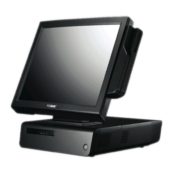
- Page 1 More than just a POS, you think User's MANUAL POSBANK Co., Ltd www.posbank.com Room 805~808, New T Castle B/D, 429-1, Gasan-Dong, Geumcheon-Gu, Seoul,Korea...
-
Page 2: Table Of Contents
INDEX Chapter 1. Caution. Chapter 3. BIOS Setup Utility Chapter 5. Mainboard Jumper Setting Product quality guarantee BIOS set up utility Motherboard and deeps Copyright BIOS menu screen location description Disclaimer Standard CMOS features Trademark recognition Advance BIOS features Federal Communication Commission Advance chipset features Declaration of conformity Integrated peripherals... - Page 3 Chapter 1. Caution.
-
Page 4: Product Quality Guarantee
POSBANK warrants our hardware POS terminal product and its par ts against defects in materials and workmanship under normal use for a standard period of two (2) year from the date of original purchase. During this period, POSBANK will repair or replace a defective product or part without charge for parts and labor to the purchaser. -
Page 5: Copyright
Copyright. > > This publication, including all photographs, illustrations and software, is protected under international copyright laws, with all rights reserved. Neither this manual, nor any of the material contained herein, may be reproduced without written consent of the author. -
Page 6: Disclaimer
Disclaimer. > > The information in this document is subject to change without notice. The manufacturer makes no representations or warranties with respect to the contents hereof and specifically disclaims any implied warranties of merchantability or fitness for any particular purpose. The manufacturer reserves the right to revise this publication and to make changes from time to time in the content hereof without obligation of the manufacturer to notify any person of such revision or changes. -
Page 7: Trademark Recognition
Trademark recognition > > All product names used in this manual are the properties of their respective owners and are acknowledged. -
Page 8: Federal Communication Commission
Federal communications commission (FCC) > > This equipment has been tested and found to comply with the limits for a Class A digital device, pursuant to Part 15 of the FCC Rules. These limits are designed to provide reasonable protection against harmful interference in a residential installation. This equipment generates, uses, and can radiate radio frequency energy and, if not installed and used in accordance with the instructions, may cause harmful interference to radio communications. -
Page 9: Declaration Of Conformity
Declaration of conformity > > This device complies with part 15 of the FCC rules. Operation is subject to the following conditions: - This device may not cause harmful interference, and - This device must accept any interference received, including interference that may cause undesired operation. -
Page 10: Caution For Safety
Caution for safety. > > - Specifications are subject to change without notice. - Avoid exposing the product to direct sunlight and do not use the product near area of high moistures. - Do not block the unit's ventilation openings. - Do not attempt to disassemble or modify this product by yourself, as doing so may expose you to an electric shock. -
Page 11: Chapter 2. Product Overview
Chapter 2. Product overview... -
Page 12: Check The Contents
Check the contents > > 3. Optional Parts 1. The following items are included when you purchased this product. 2. If any of these items are damaged or missing, contact your dealer for assistance. Customer display with stand POS MAIN BODY POWER CORD USER'S MANUAL, DRIVER CD... -
Page 13: Each Part Of Main Body Name
Each part of main body name > > FRONT VIEW REAR VIEW Touch Panel Display Display Hinge Customer Display Cover Power Button Real For Cable USB PORT Management POWER·HDD·LAN LED Real Connectors... - Page 14 Each part of main body name > > Rear Connectors I/O Monitor Connector (option) PS/2 Mouse Connector Connector COM2 Port Parallel Port COM1 Port COM3 Port USB Port AC IN POWER Connector PS/2 KEYBOARD Audio port (Line in, Speaker out, Mic in) Connector...
- Page 15 Option parts installation > > Customer Display(VFD) & 2nd Monitor Installation Connect the display cable and insert VFD(2nd Monitor) set, use 4 screws to secure the VFD(2nd Monitor) set. VFD(2nd Monitor) is connected to internal COM4. Caution; To install or withdraw VFD(2nd Monitor), power must be switch off.
- Page 16 Chapter 3. BIOS Setup Utility...
-
Page 17: Bios Set Up Utility
Bios setup utility > > This motherboard supports a programmable firmware chip that you can update using the provided utility. Use the BIOS Setup program when you are installing a motherboard, reconfiguring your system, or prompted to "Run Setup." This section explains how to configure your system using this utility. Even if you are not prompted to use the Setup program, you can change the configuration of your computer in the future. - Page 18 Bios setup utility > > The keys in the legend bar allow you to navigate through the various setup menus Key(s ) Key(s ) Function Description Function Description General help, only for Status Page Setup Menu and Option Page Se tup Menu Return to the main menu from a submenu or prompts you to quit the setup program.
-
Page 19: Bios Menu Screen
Bios setup utility > > BIOS Menu Screen When you enter the BIOS, the following screen appears. The BIOS menu screen displays the items that allow you to make changes to the system configuration. To access the menu items, press the up/down/right/left arrow key on the keyboard until the desired item is highlighted, then press [Enter] to open the specific menu. -
Page 20: Standard Cmos Features
Bios setup utility > > Standard BIOS Features. The Standard CMOS Features screen gives you an overview of the basic system Date [Day, xx/xx/xxxx] The date format is <week>, <month>, <day>, <year>. Time [xx:xx:xx] The time format is <hour><minute><second>, based on the 24-hour clock. -
Page 21: Advanced Bios Features
Bios setup utility > > Advanced BIOS Features. The "Advanced BIOS Features" screen appears when choosing the "Advanced BIOS Features" item from the "Initial Setup Screen" menu. It allows the user to configure the motherboard according to his particular requirements. Below are some major items that are provided in the Advanced BIOS Features screen. - Page 22 Bios setup utility > > Advanced BIOS Features. Boot Other Device Use this to boot another device. The options are “Enabled” and “Disabled” Boot Up NumLock Status Set the boot up Num Lock status. The options are “On” and “Off”. Gate A20 Option Normal : A pin in the keyboard controller controls GateA20 Fast : Lets chipset control GateA20 (Default)
-
Page 23: Advanced Chipset Features
Bios setup utility > > Advanced Chipset Features. DRAM Timing Selectable This item allows you to select the DRAM timing value by SPD data or Manual by yourself. The choices: Manual, By SPD. System BIOS Cacheable Selecting "Enabled" allows caching of the system BIOS ROM at F0000h- FFFFFh, resulting in better system performance. -
Page 24: Integrated Peripherals
Bios setup utility > > Integrated Peripherals Use this menu to specify your settings for integrated peripherals. -
Page 25: Onboard Device
Bios setup utility > > Integrated Peripherals [On Chip IDE Device] IDE HDD Block Model If the IDE hard drive supports block mode select Enabled for automatic detection of the optimal number of block read/writes per sector the drive can support. IDE DMA Transfer Access Use this field to enable or disable IDE DMA transfer access. - Page 26 Bios setup utility > > Integrated Peripherals [Super I/O Device] Power ON Function This feature allows you to wake up the system using any of the listed options. The options: [Mouse Left], [Mouse Right], [Any KEY], [Button Only]. Onboard Serial Port Select an address and corresponding interrupt for the first and second serial ports.
- Page 27 Bios setup utility > > Integrated Peripherals Onboard LAN Boot ROM The options are [disabled], [enable]. Watch Dog Timer Select This option will determine watchdog timer. The choices: Disabled, 10, 20, 30, 40 Sec. 1, 2, 4 Min. Onboard Serial Port 3 Select an address and corresponding interrupt for the serial ports.
- Page 28 Bios setup utility > > Integrated Peripherals [USB Device Setting] USB 1.0 / 2.0 Controller The choices: Disabled, Enabled. USB Operation Mode Allow you to configure the USB 2.0 controller in HiSpeed (480 Mbps) or Full Speed (12 Mbps). Configuration options: [Full/Low Speed] [HiSpeed] USB Keyboard Function The choices: Disabled, Enabled.
-
Page 29: Power Management Set Up
Bios setup utility > > Power Management Setup. The power management setup controls the single board computer's "green" features to save power. The following screen shows the manufacturer's defaults. ACPI Function The choices are “Enabled” and “Disabled”. ACPI Suspend Type This item allows you to set ACPI suspend type to S1/POS(Power On Suspend) or S3/STR (Suspend To RAM). -
Page 30: Power Management Setup
Bios setup utility > > Power Management Setup. Wake-Up by PCI Card This will enable the system to wake up through PCI/LAN peripheral. The choices: Enable, Disabled. Power On by Ring Select “Enabled” to power on the system from a soft off state by an input signal on the serial Ring Indicator (RI) line. -
Page 31: Pnp/Pci Configurations
Bios setup utility > > PnP/PCI Configurations Rest Configuration Data The default is “Disabled”. Select Enabled to reset Extended System Configuration Data (ESCD) if you have installed a new add-on card, and system configuration is in such a state that the OS cannot boot. Resource Controlled By The commands here are “Auto(ESCD)”... -
Page 32: Pc Health Status
Bios setup utility > > PC Health Status System Temperature This shows you the current temperature of system. CPU Temperature This shows the current CPU temperature. Chassis FAN Speed This shows the Chassis FAN Speed (RPM). CPU FAN Speed This shows the CPU FAN Speed.(RPM) VCore and Others Voltage This shows the voltage of VCORE, +5V, +12V, VCC(V), AVCC(V), VCC3(V), VBAT(V), and 3VSB(V). -
Page 33: Load Set Up Defaults
Bios setup utility > > Load Setup Defaults Use this menu to load the BIOS default values that are factory settings for optimal performance system operations. While Award has designed the custom BIOS to maximize performance, the factory has the right to change these defaults to meet their needs. -
Page 34: Set Passwords
Bios setup utility > > Set Password. You can set password. It is able to entel / change the options of setup menus. - Page 35 Bios setup utility > > Save and Exit Setup. If you select this and press <Enter>, the values entered in the setup utilities will be recorded in the CMOS memory of the chipset. The processor will check this every time you turn your system on and compare this to what it finds as it checks the system.
-
Page 36: Exit Without Saving
Bios setup utility > > Exit without saving Selecting this option and pressing <Enter> lets you exit the setup program without recording any new values or changing old ones. -
Page 37: Chapter 4. Trouble Shooting
Chapter 4. Trouble Shooting... -
Page 38: General Checkout Guidelines
Trouble shooting > > General checkout guidelines Use the following procedure to troubleshoot problems: - Identify as many symptoms as possible in detail. - Verify symptoms by recreating them. - Follow the corrective procedures in order. - If you replace an FRU and the symptom remains, reinstall the original FRU before going to the next step. Do not replace non-defective FRUs. -
Page 39: Network Symptom
Trouble shooting > > Network Symptom - Check hub / switch is working correctly - Check the RJ45 cable Cannot access LAN - Check the RJ-45 LEDs are on - Reinstalled LAN card - Replace main board MSR Symptom MSR does not response - Check the MSR reader cable - Check the main board to LCD cable - Check the MSR board cable... -
Page 40: Cash Drawer Symptom
Trouble shooting > > Cash drawer Symptom Cash drawer does not function - Check the cash drawer cable - Replace the cash drawer cable LCD Symptom LCd backlight is not working but text is still - Check the LCD cable visible on screen - Check the inverter cable - Replace the inverter cable... -
Page 41: Power Symptom
Trouble shooting > > Power Symptom - Check the A/C cable - Check the main board power connector Power shut down unexpectedly can not - Check the CPU setting turn the system - Check the DRAM setting - Check the power button cable - Replace the power supply unit PS/2 Keyboard Symptom PS/2 Keyboard does not function... - Page 42 Chapter 5. Mainboard Jumper Setting...
- Page 43 Mainboard and PCB jumper setting > >...
-
Page 44: Location Description
Mainboard and PCB jumper setting method > > Mainboard and dip switch location description Slots Slots Label Function Note CompactFlash socket DIMMA1 240- pin DDR2 DIMM slot DIMMB1 240- pin DDR2 DIMM slot Jumpers Jumpers Label Function Note CLRRTC1 Clear CMOS 3 x 1 header, pitch 2.54mm JCOMPWR1 COM port 1,2 RI/+5V/+12V selection... -
Page 45: Location Description
Mainboard and PCB jumper setting method > > Mainboard and deeps location description Internal Connector Internal Connector Label Function Note AMPJ1 Amplifier connector 4 x 1 header, pitch 2.54mm CPU_FAN1 CPU fan connector 3 x 1 wafer, pitch 2.54mm SYS_FAN1 System fan connector 3 x 1 wafer, pitch 2.54mm COM3... -
Page 46: Chapter 6. Replacing Parts
Chapter 6. Replacing Parts... -
Page 47: Safety And Precautions
- After replacing optional devices, make sure all screws, springs, or other small parts are in place and are not left loose inside the case. - Metallic parts or metal flakes can cause electrical shorts. - Only qualified personnel should perform repairs on the SlimPOS. Damage due to unauthorized servicing is not covered by the warranty. -
Page 48: Before You Begin
> > Before you begin Make sure you have a stable, clean working environment. Dust and dirt can get into SlimPOS components and cause a malfunction. Adequate lighting and proper tools can prevent you from accidentally damaging the internal components. - Page 49 Replacing Field Replaceable Units > > ■ Replacing parts Take note of the following when replacing parts: - If you replace an FRU and the symptom remains, reinstall the original FRU before going to the next step. Do not replace non-defective FRUs.
- Page 50 Replacing Field Replaceable Units > > Mainboard 2. Loosen the 3 screws by screwdriver 3. Remove the rear cover 1. Remove the cable cover as described in holes 6. Loosen the 2 screws 5. Remove the metal case cover 4. Loosen the 4 screws...
- Page 51 Replacing Field Replaceable Units > > Mainboard 7. Remove the hinge cover 8. Loosen the 2 screws 9. Remove the part as shown 12. Loosen the 12 screws 10. Loosen the 6 screws 11. Remove the monitor hinge cover...
- Page 52 Replacing Field Replaceable Units > > Mainboard 13. Disconnect the 2 monitor cable 14. Remove the front cover and 15. Loosen the 6 screws and metal from mainboard disconnect the 2 cables cover remove 17. Loosen the 4 screws 18. Loosen the 2 screws from the 16.
- Page 53 Replacing Field Replaceable Units > > Replace MSR 1. Loosen the 2 screws 2. Disconnect the cable. 3. Separate the MSR. 4. After replace MSR, assemble in a reverse way.
- Page 54 Replacing Field Replaceable Units > > Replace memory(RAM) method 1. Open the release latches 2. Remove the memory...
- Page 55 Replacing Field Replaceable Units > > Replace Heatsink & FAN 1. Separate the connector from 2. Loosen 2 screws Pull up Heatsink & Fan and separate from CPU the mainboard.
- Page 56 Replacing Field Replaceable Units > > Replace CPU 1. Remove the Heatsink 2. Turn the locking screw 180 3. Remove the CPU degrees...
- Page 57 Replacing Field Replaceable Units > > Replace HDD 1. Loosen the screw to open a 2. Release the 4 locking screws 3. Disconnect the 2 cables and release HDD cover the 4 screws on the side to remove the HDD...
- Page 58 Replacing Field Replaceable Units > > Replace Power supply 1. After remove HDD, separate 2. Loosen 3 screws 3. Remove the power supply bracket bottom cover by loosen 4 screws. 4. After replac e Power supply, assemble in a reverse way.
- Page 59 Replacing Field Replaceable Units > > Replace Monitor 3. Loosen the 2 screws 2. Remove the hinge cover 1. Loosen the 2 screws 6. Remove the monitor hinge 4. Remove the part as sharn 5. Loosen the 6 screws cover...
- Page 60 Replacing Field Replaceable Units > > Replace Monitor 8. Disconnect the 2 monitor cable 9. replace monitor 7. Loosen the 12 screws from mainboard...
- Page 61 Replacing Field Replaceable Units > > Replace Monitor board, Inverter, Touch panel, LCD Panel 1. Separate the part 2. Loosen the 6 screws and separate the 3. Loosen the 11 screws to separate the display cover metal cover 3. Loosen the 4 screws and disconnect 5.
- Page 62 Replacing Field Replaceable Units > > Replace Monitor board, Inverter, Touch panel, LCD Panel 7. Loosen the 16 screws to separate 8. Separate touch panel from LCD panel LCD panel.
-
Page 63: Power Supply
Reference to upgrade & Power supply > > Reference to Upgrade 1. CPU: Intel C Mobile 1.6 GHz ~ 2.2 GHz 2. RAM: one DIMM up to 2GB DDR2 400/533 SO-DIMM 3. HDD: 2.5" SATA HDD 80GB above. Power supply Power Type 0 ~ 60°C (32 ~ 140°F) Operating... -
Page 64: Specifications
Specification > > SLIMPOS_Specification Items Specification Intel C Mobile 1.5 GHz HDD 2.5 Inch 80GB SATA Memory DDR2 SODIMM 512MB VGA card Intel 82915GV GMCH integrated Graphics Media Accelerator 900 Display 15" TFT LCD (1024×768, 5-wire resistive touch screen Internal I/O RS232-C port (COM4, COM5, COM6) -USB 4 ports (front:2, rear:2) Standard I/O...
Need help?
Do you have a question about the SlimPOS and is the answer not in the manual?
Questions and answers