Advertisement
BR20 Magnetic Card Reader
Installation and Maintenance
1. General:
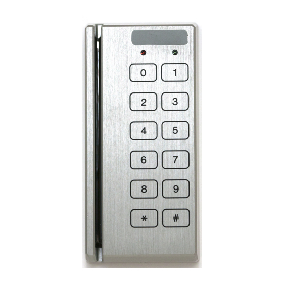
The BR20 magnetic stripe card reader is designed for reading standard or high-coercivity magnetic stripe cards. The
BR20 also provides a 12-key keypad for PIN entry and provides a TTL interface. The following paragraphs describe
instructions for installing and maintaining the card reader. The BR20 does not support the tamper switch option.
2. Mounting the Reader:
Find a suitable location to anchor the reader mounting bracket. The reader may be mounted vertically or horizontally.
See recommended orientation. The mounting of the reader does not require a junction box. However, rigid conduit
is required for outdoor application. A single gang junction box may be used to provide a transition to rigid conduit.
If a single gang junction box is used, a wall plate (optional) may be used to cover the junction box. The reader is then
secured to the mounting bracket using a screw. Refer to figures for reader dimensions and typical junction box usage.
3. Reader Wiring:
The reader has a RJ-11 modular jack for easy field connection. A short piece of pre-terminated cable is supplied with
each standard reader for field wiring. The pre-terminated cable has nonstandard color. Refer to pin number if the pre-
terminated cable is not used. Cable with wires of 24AWG or larger are recommended for field wiring.
4. Connecting the Keypad:
The BR20 provides a 12-key keypad for PIN entry. The flex tail of the keypad is connected to the electronic board via
a ZIF (zero insertion force) connector. The contacts are engaged/disengaged by a moving slide. Care must be
exercised when connecting and disconnecting the keypad. When connecting the keypad to the board, open the slide
as shown. Insert the electronics into the housing and insert flex tail in the ZIF connector. Then, close the slide to engage
the contacts. To disconnect the keypad, follow the previously described steps in reverse.
5. Weather Proofing the Reader:
CONFIDENTIAL: For installation and maintenance use only. DO NOT distribute.
©
Mercury Security Corporation,
2355 MIRA MAR AVE. LONG BEACH, CA 90815-1755, (562) 986-9105 FAX (562) 986-9205
BR20
Doc. 10107-0024 rev. 1.03 10/2008
2008
www.mercury-security.com
This device complies with part 15 of the FCC Rules.
Operation is subject to the following two conditions:
(1) This device may not cause harmful interference,
and (2) this device must accept any interference
received, including interference that may cause un-
CAUTION: DO NOT DISCONNECT
KEYPAD WITHOUT DISENGAGING
THE CONNECTOR!
Page 1
Advertisement
Table of Contents

Summary of Contents for Mercury BR20
-
Page 1: Installation And Maintenance
4. Connecting the Keypad: The BR20 provides a 12-key keypad for PIN entry. The flex tail of the keypad is connected to the electronic board via a ZIF (zero insertion force) connector. The contacts are engaged/disengaged by a moving slide. Care must be exercised when connecting and disconnecting the keypad. -
Page 2: Ttl Interface
8. DIP Switch Setting: The DIP switch on the BR20 reader is used to select a preset format, the functions for the LED and buzzer, and the output signal format, etc. The preset format determines how the card is interpreted. Refer to the format specification for detail. - Page 3 9. BR20 Standard Format Code Summary: The following formats are supported in standard models (31002-8000/31012-8000). Unless otherwise indicated, the LED input line controls both LEDs (low=green, high=red); the BUZZER input controls the buzzer (low = activate); a good read is signaled by a flash of the green LED; a bad read is signaled by a flash of the red LED and a double beep of the buzzer.
-
Page 4: Specifications
1,000,000 passes typical. Distance: 500' (152m) with 18 AWG wires. Environmental: Temperature -55 to +85 degrees C, storage -40 to +75 degrees C, operating Humidity 0-100% RHNC © Page 4 BR20 Doc. 10107-0024 rev. 1.03 10/2008 Mercury Security Corporation, 2008... - Page 5 1.30 [33] 2X Ø .18 [4.5] MOUNTING HOLE 3.30 [84] 2.60 [66] 0.99 [25] DIMENSION: INCH [mm] Optional Wall Plate (part# WP10) Fitting Rigid Conduit to Junction Box © Page 5 BR20 Doc. 10107-0024 rev. 1.03 10/2008 Mercury Security Corporation, 2008...
-
Page 6: Warranty
This warranty is limited to the repair or replacement of the defective unit. There are no expressed warranties other than set forth herein. Mercury Security Corporation does not make, nor intends, nor does it authorize any agent or representative to make any other warranties, or implied warranties, and expressly excludes and disclaims all implied warranties of merchantability or fitness for a particular purpose.
Need help?
Do you have a question about the BR20 and is the answer not in the manual?
Questions and answers