Table of Contents
Advertisement
Quick Links
VENT-FREE NATURAL
OWNER'S OPERATION AND INSTALLATION MANUAL
®
WARNING: If the information in this manual is not followed exactly, a fire or
explosion may result causing property damage, personal injury, or loss of life.
— Do not store or use gasoline or other flammable vapors and liquids in the
vicinity of this or any other appliance.
— WHAT TO DO IF YOU SMELL GAS
• Do not try to light any appliance.
• Do not touch any electrical switch; do not use any phone in your building.
• Immediately call your gas supplier from a neighbor's phone. Follow the gas
supplier's instructions.
• If you cannot reach your gas supplier, call the fire department.
— Installation and service must be performed by a qualified installer, service
agency, or the gas supplier.
This appliance may be installed in an aftermarket* manufactured (mobile) home,
where not prohibited by state or local codes.
* Aftermarket: Completion of sale, not for purpose of resale, from the manufacturer
This appliance is only for use with the type of gas indicated on the rating plate.
This appliance is not convertible for use with other gases.
GAS HEATER
14,000 to 28,000 Btu/Hr Thermostat
Model: GM280TNG
Save this manual for future reference.
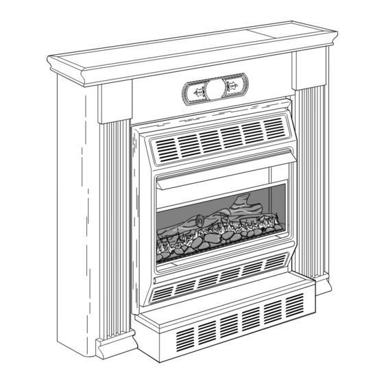
Shown with Optional
Hearth Base and Mantel
Advertisement
Table of Contents

Subscribe to Our Youtube Channel
Summary of Contents for PERFECTION-SCHWANK GM280TNG
- Page 1 Shown with Optional Hearth Base and Mantel 14,000 to 28,000 Btu/Hr Thermostat Model: GM280TNG WARNING: If the information in this manual is not followed exactly, a fire or explosion may result causing property damage, personal injury, or loss of life.
-
Page 2: Table Of Contents
SECTION PAGE CONTENTS Safety Information ..................2 Product Identification ................4 Local Codes ....................4 Product Features ..................4 Unpacking ....................4 Assembly ....................5 Air for Combustion and Ventilation ............8 Installation ....................12 Connecting to Gas Supply ................ 18 Checking Gas Connections ............... - Page 3 SAFETY WARNINGS Continued WARNING ICON G 001 INFORMATION WARNING: Any change to this heater or its controls can be dangerous. Continued 1. This appliance is only for use with the type of gas indicated on the rating plate. This appliance is not convertible for use with other gases. 2.
-
Page 4: Product Identification
Ignitor Button Control Knob PRODUCT Lighting and Warning IDENTIFICATION Plates Heater Screen Cabinet Front Panel Figure 1 - Vent-Free Gas Log Natural Gas Space Heater LOCAL CODES Install and use heater with care. Follow all local codes. In the absence of local codes, use the latest edition of The National Fuel Gas Code ANSI Z223, also known as NFPA 54*. -
Page 5: Assembly
ASSEMBLING HEATER ASSEMBLY Tools Required: Phillips screwdriver, 5/16" hex wrench, and slotted screwdriver Removing Front Panel Of Heater 1. Remove two screws near bottom corners of front panel with Phillips screwdriver. 2. Pull bottom of front panel forward, then down (see Figure 2) . Figure 2 - Removing Front Panel of Heater Installing Log For easier installation, lay heater on its back. - Page 6 ASSEMBLY WARNING WARNING ICON G 001 Continued Always have burner shield and screen in place before operating heater. This prevents excessive temperatures on heater surfaces. Heater Cabinet Deflector Front Panel Retaining Brackets Screen Truss- Head Screw Burner Shield Screw Brass Front Screw Trim...
- Page 7 ASSEMBLY Assembling and Attaching Brass Trim 1. Remove packaging from remaining three pieces of brass trim. Continued 2. Locate four brass screws, two adjusting plates with set screws, and two shims in the hardware packet. 3. Align shim under adjusting plate as shown in Figure 6. 4.
-
Page 8: Air For Combustion And Ventilation
AIR FOR WARNING WARNING ICON G 001 COMBUSTION This heater shall not be installed in a confined space unless provisions are provided for adequate combustion and ventilation air. Read the following instructions to insure proper fresh air for VENTILATION this and other fuel-burning appliances in your home. Today’s homes are built more energy efficient than ever. - Page 9 AIR FOR DETERMINING AIR FLOW FOR HEATER LOCATION Determining if You Have a Confined or Unconfined Space COMBUSTION Use this worksheet to determine if you have a confined or unconfined space. Space: Includes the room in which you will install heater plus any adjoining rooms with VENTILATION doorless passageways or ventilation grills between the rooms.
- Page 10 AIR FOR WARNING WARNING ICON G 001 COMBUSTION If the area in which the heater may be operated is smaller than that defined as an unconfined space, provide adequate combus- tion and ventilation air by one of the methods described in the VENTILATION National Fuel Gas Code, ANSI Z223.1, 1992, Section 5.3.
- Page 11 Ventilation Air From Outdoors AIR FOR Provide extra fresh air by using ventilation grills or ducts. You must provide COMBUSTION two permanent openings: one within 12" of the ceiling and one within 12" of the floor. Connect these items directly to the outdoors or spaces open to the outdoors.
-
Page 12: Installation
INSTALLATION NOTICE A qualified service person must install heater. Follow all local codes. CHECK GAS TYPE Use only natural gas. If your gas supply is not natural gas, do not install heater. Call dealer where you bought heater for proper type heater. INSTALLATION ITEMS Before installing heater, make sure you have the items listed below. - Page 13 INSTALLATION CAUTION WARNING ICON G 001 Continued If you install the heater in a home garage • heater pilot and burner must be at least 18 inches above floor. • locate heater where moving vehicle will not hit it. For convenience and efficiency, install heater •...
- Page 14 INSTALLATION OPTIONS INSTALLATION There are three options for mounting this heater. Continued A. Mounting heater to wall B. Mounting heater to optional hearth base C. Mounting heater with optional hearth base to optional mantel. A. MOUNTING HEATER TO WALL Mounting Bracket The mounting bracket is located on back panel of heater.
- Page 15 INSTALLATION Attaching Mounting Bracket To Wall Wall anchors, mounting screws, and spacers are in hardware package. The Note: Continued hardware package is provided with heater. Attaching to wall stud method For attaching mounting bracket to wall studs 1. Drill holes at marked locations using 9/64" drill bit. 2.
- Page 16 INSTALLATION Installing Bottom Mounting Screws 1. Locate two bottom mounting holes. These holes are near bottom on back panel Continued of heater (see Figure 17). 2. Mark screw locations on wall. 3. Remove heater from mounting bracket. 4. If installing bottom mounting screws into hollow or solid wall, install wall anchors. Follow steps 1 through 4 under Attaching To Wall Anchor Method, page 15.
- Page 17 Mounting Heater to Optional Hearth Base INSTALLATION 1. Lay heater on its back on a table with the bottom of heater overhanging the edge Continued of the table. 2. Remove 2 shipping screws in bottom of heater. Discard shipping screws. 3.
-
Page 18: Connecting To Gas Supply
CONNECTING NOTICE TO GAS A qualified service person must connect heater to gas supply. Follow all local codes. SUPPLY WARNING WARNING ICON G 001 Never connect heater to private (non-utility) gas wells. This gas is commonly known as wellhead gas. Check gas line pressure before connecting heater to gas line. -
Page 19: Checking Gas Connections
CONNECTING Hold pressure regulator with wrench when connecting it to gas piping IMPORTANT: and/or fittings. TO GAS Burner bracket Note: SUPPLY not shown for clarity Pressure Regulator Continued 1/2" NPT Pipe Nipple Heater Ground Cabinet Union Joint Tee Joint Manual Shutoff Valve * Test Reducer Bushing to... - Page 20 CHECKING 4. Check all joints of gas supply piping system. Apply mixture of liquid soap and water to gas joints. Bubbles forming show a leak. 5. Correct all leaks at once. CONNECTIONS Test Pressures Equal To or Less Than 1/2 PSIG 1.
-
Page 21: Operating Heater
OPERATING FOR YOUR SAFETY READ BEFORE LIGHTING HEATER WARNING WARNING ICON G 001 If you do not follow these instructions exactly, a fire or explo- sion may result causing property damage, personal injury or loss of life. A. This appliance has a pilot which must be lighted by hand. When lighting the pilot, follow these instructions exactly. - Page 22 OPERATING 4. Wait five (5) minutes to clear out any gas. Then smell for gas, including near the floor. If you smell gas, STOP! Follow “B” in the safety information HEATER at the top of page 21. If you don’t smell gas, go to the next step. Continued 5.
- Page 23 OPERATING TO TURN OFF GAS TO APPLIANCE HEATER Shutting Off Heater Continued 1. Turn control knob clockwise to the OFF position. Clockwise 2. Turn off all electric power to the appliance if service is to be performed. Shutting Off Burner Only (pilot stays lit) 1.
-
Page 24: Inspecting Burner
Check pilot flame pattern and burner flame pattern often. INSPECTING BURNER PILOT FLAME PATTERN Figure 25 shows a correct pilot flame pattern. Figure 26 shows an incorrect pilot flame pattern. The incorrect pilot flame is not touching the thermocouple. This will cause the thermocouple to cool. - Page 25 INSPECTING BURNER FLAME PATTERN Figure 27 shows a correct burner flame pattern. Figure 28 shows an incorrect BURNER burner flame pattern. The incorrect burner flame pattern shows yellow tipping of the flame. It also shows the flame higher than one inch above the log. Continued When using the heater the first time, the flame will be yellow for approxi- Note:...
-
Page 26: Cleaning And Maintenance
CLEANING WARNING WARNING ICON G 001 Turn off heater and let cool before cleaning. MAINTENANCE CAUTION WARNING ICON G 001 You must keep control areas, burner, and circulating air passage- ways of heater clean. Inspect these areas of heater before each use. - Page 27 TROUBLE- OBSERVED POSSIBLE PROBLEM CAUSE REMEDY SHOOTING When ignitor button 1. Gas supply turned off 1. Turn on gas supply or Continued is pressed, there is or manual shutoff open manual shutoff spark at ODS/pilot valve closed valve but no ignition 2.
- Page 28 OBSERVED POSSIBLE TROUBLE- PROBLEM CAUSE REMEDY SHOOTING Burner does not light 1. Burner orifice is 1. Clean burner (see Continued after ODS/pilot is lit clogged Cleaning and Mainte- nance, page 26) or replace burner orifice 2. Burner orifice diameter 2. Replace burner orifice is too small 3.
- Page 29 TROUBLE- WARNING WARNING ICON G 001 SHOOTING If you smell gas Continued • Shut off gas supply. • Do not try to light any appliance. • Do not touch any electrical switch; do not use any phone in your building. •...
-
Page 30: Technical Service
You may have further questions about installation, operation, or troubleshooting. TECHNICAL If so, contact Perfection-Schwank’s Technical Service Department at 1-800-776-8459 SERVICE (outside GA) or 706-554-2101. SPECIFICATIONS Model GM280TNG Btu (Variable) 14,000/28,000 Type Gas Natural Only Ignition Piezo Pressure Regulator Setting 3"... -
Page 31: Accessories
Purchase these heater accessories from your local dealer. If they can not supply ACCESSORIES these accessories, call Perfection-Schwank’s Sales Department at 1-800-776-8459 (outside GA) or 706-554-2101 for information. You can also write to the address listed on the back page of this manual. - Page 32 ACCESSORIES FINISHED MANTEL GM280MF For use with heater and hearth base. Sturdy hardwood construc- tion embellished with fluted sides, raised medallions, and carved rope trim. Available in a walnut finish, ready to stain or paint. Complete assembly and installation instructions included. UNFINISHED MANTEL GM280MU For use with heater and hearth...
-
Page 33: Illustrated Parts List
12-1 12-2 103092... -
Page 34: Parts List
This list contains replaceable parts used in your heater. When ordering parts, follow PARTS LIST the instructions listed under Replacement Parts on page 30 of this manual. Model: GM280TNG VMH2800TNB/ CFMH2800TNB PART NO. DESCRIPTION QTY. 098304-01 Screw, #10 x 3/8"... - Page 35 NOTES _________________________________________________________________ _________________________________________________________________ _________________________________________________________________ _________________________________________________________________ _________________________________________________________________ _________________________________________________________________ _________________________________________________________________ _________________________________________________________________ _________________________________________________________________ _________________________________________________________________ _________________________________________________________________ _________________________________________________________________ _________________________________________________________________ _________________________________________________________________ _________________________________________________________________ _________________________________________________________________ _________________________________________________________________ _________________________________________________________________ _________________________________________________________________ _________________________________________________________________ _________________________________________________________________ _________________________________________________________________ _________________________________________________________________ _________________________________________________________________ _________________________________________________________________ _________________________________________________________________ _________________________________________________________________ _________________________________________________________________ _________________________________________________________________ _________________________________________________________________ _________________________________________________________________ _________________________________________________________________ _________________________________________________________________ _________________________________________________________________ _________________________________________________________________ _________________________________________________________________ _________________________________________________________________ _________________________________________________________________ _________________________________________________________________ 103092...
-
Page 36: Warranty Information
VENT-FREE NATURAL GAS HEATERS Perfection-Schwank warrants this product to be free from defects in materials and components for one (1) year from the date of first purchase, provided that the product has been properly installed, operated and maintained in accordance with all applicable instructions.
Need help?
Do you have a question about the GM280TNG and is the answer not in the manual?
Questions and answers