Table of Contents
Advertisement
Advertisement
Table of Contents

Subscribe to Our Youtube Channel
Summary of Contents for EuroMini 10V6.e
- Page 1 I n s t a l l a t i o n M a n u a l EN50131-1 RINS1211-4...
-
Page 3: Table Of Contents
ontents Page System Overview Technical Specification Overview The Control Panel The Printed Circuit Board The Tamper Spring and Connections Connections Transformer / Battery Connection Keypad Connection Reader Connection Double Pole - Alarm Connections Double Pole - Tamper Connections DEOL: 4K7 Alarm, 2K2 Tamper DEOL: 4K7 Alarm, 4K7 Tamper Siren Connection Speaker Connection... -
Page 4: System Overview
ystem Overview Inputs on main 10 fully programmable inputs control panel Input configuration Double end of line (4K7 Alarm, 2K2 Tamper) Double end of line (4K7 Alarm, 4K7 Tamper) Double Pole Input Types Unused, Fire, Hold Up, 24 Hour, Intruder, Final Exit, Entry Route, ER (FX in part), FX (ER in part), Keyswitch Latched, Keyswitch Pulsed Programmable... -
Page 5: Technical Specification
echnical Specification Electrical Specification Supply Voltage (A.C.) 18VAC Nominal (+-20%), 50Hz (+-10%) Supply Voltage (D.C.) 12VDC Nominal (10-15 Volt DC Range) Power Supply 1A Regulated Supply Current <80mA Quiescent (DC supply, no active outputs) 800mA continous, 13.68V nominal (fold-back Internal battery charger current limited) Battery supply protection Reverse polarity protected Battery final disconnect... -
Page 6: Overview
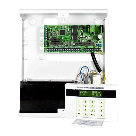
verview Control Panel The EURO mini is already fully assembled in a metal case. The diagram below shows a basic overview of the different components. The Control Panel Wall Fixing Holes BELL BATTERY Remove for DP Z1 GND Z2 GND +12V Z3 GND Z5 GND Z6 GND +12V Z7 GND Z9 GND Z10... -
Page 7: The Printed Circuit Board
verview Printed Circuit Board The EURO mini printed circuit board is as follows: The Printed Circuit Board Power LED Fuses (flashes) BELL Fuses BATTERY Remove for DP Z1 COM Z2 COM +12V Z3 COM Z4 Z5 COM Z6 COM +12V Z7 COM Z9 COM Z10 D1- D2+ D3 - BAT + GND... -
Page 8: The Tamper Spring And Connections
verview Tamper Connections The EURO mini printed circuit board is protected by a metal casing. The lid is tampered by a spring that is connected to the printed circuit board. To disable the tamper spring, simply link out the tamper connections shown below. -
Page 9: Connections
onnections Transformer Battery The transformer will be factory fitted to the connections shown below on the EURO mini. It is recommended that a 3Ah or 7Ah battery should be used on the EURO mini. This connects to the Battery positive and negative terminals. Transformer / Battery Connection BELL BATTERY... -
Page 10: Keypad Connection
onnections Contemporary Keypad A maximum of 4 keypads may be installed to the EURO mini. Each keypad (EUR-068 or EUR-069) connects to the RS485 terminal: D1-, D2+, D3 and D4. Each keypad must be individually addressed, starting with 00. To do this, press and hold the ‘D’... -
Page 11: Reader Connection
onnections Internal Tag Reader A maximum of 3 readers may be installed to the EURO mini if the EUR-068 is installed. Each connect to the RS485 terminal: D1-, D2+, D3 and D4. Each reader must be individually addressed, starting with 01. To do this, there are dip switches on the back of the reader. -
Page 12: Double Pole - Alarm Connections
onnections Double Pole BELL Input Wiring If double pole is used, the link above input 1 (shown below) needs to be open. BATTERY Remove for DP Double pole requires no resistors, but it requires a dedicated tamper circuit (When a clean start 2002 is performed, input 1 is defaulted as tamper). The first diagram below shows the connection of door contacts/detectors to the Z1 COM Z2 COM +12V Z3 COM Z4 Z5 COM... -
Page 13: Deol: 4K7 Alarm, 2K2 Tamper
onnections Resistor Input Wiring If double end of line is used, the link above input 1 (shown below) needs to be closed, and specific resistors need to be used depending on which mode is BELL selected (see Choose Mode in the programming manual). There are 2 choices: DEOL: 4K7 Alarm, 2K2 Tamper BATTERY Remove for DP... -
Page 14: Siren Connection
onnections Siren Connection Speaker Connection The connections for a +12V Siren are described below, at default all outputs are negative applied and this cannot be altered. There is also a connection for 1 or 2 16ohm speakers, which will follow the keypad sounds. -
Page 15: Output Connection/Example
onnections Output Connections The EURO mini supports up to 7 outputs. 4 of the outputs are shared with inputs on the system, therefore if the outputs are used (see Change Outputs in the programming manual), inputs 7 to 10 become disabled. All outputs on the system are negative applied and cannot be altered. -
Page 16: Compliance Statement And Warranty
ompliance Statement and Warranty Compliance Statement The EURO mini complies with the requirements of the EMC Directive (2004/108/ EC) and the Low Voltage Directive (2006/95/EC). The EURO mini complies with TS50131-3:2003 Suitable for use in systems installed to PD6662 (AMD2) at security grade 1 or 2X and environmental class 2. -
Page 17: Input Table Appendix
nput Table Appendix Input Input Type Input Areas Description Number Castle Care-Tech Page:17... - Page 18 Page:18 Castle Care-Tech...
- Page 19 Castle Care-Tech Page:19...
- Page 20 Contact Details Castle Care-Tech Ltd First Floor 6 Bracknell Beeches Old Bracknell Lane West Bracknell Berkshire RG12 7BW Helpdesk: 01344 469499 Opening Hours: 7.00am - 7.30pm Monday to Friday E-mail: support@castle-caretech.com Website: www.castle-caretech.com...
Need help?
Do you have a question about the 10V6.e and is the answer not in the manual?
Questions and answers