Table of Contents
Advertisement
Advertisement
Table of Contents

Related Manuals for Magmate 180P


Summary of Contents for Magmate 180P
- Page 1 180 P O P E R AT I N G M A N U A L...
-
Page 2: Welcome To A Better Way Of Welding
Congratulations on purchasing a MagMate 180P welding machine. This operating manual provides the basic knowledge required for MIG Welding, as well as highlighting important areas of how to operate the MagMate machine. With normal use and by following these recommended steps, your MagMate machine can provide you with years of trouble-free service. -
Page 3: Table Of Contents
Contents 1.0 Recommended Safety Precautions 5.0 Troubleshooting and Fault Finding Health Hazard Information Personal Protection 6.0 Machine Specifications Electrical Shock User Responsibility 7.0 Operating Controls and Contents Machine Setup 2.0 MIG Operating Manual Introduction to Metal Inert Gas (MIG) 8.0 Periodic Maintenance Introduction to Flux Cored Arc Welding Power Source (FCAW) -
Page 4: Recommended Safety Precautions
1.0 Recommended Safety Precautions 1.1 Health Hazard Information such as stainless steel, nickel, nickel alloys or galvanised steel, further precautions are The actual process of MIG welding is necessary. one that can cause a variety of hazards. All appropriate safety equipment should be •... -
Page 5: Electrical Shock
1.3 Electrical Shock • Never touch ‘live’ electrical parts. • Always repair or replace worn or damaged parts. • Disconnect power source before performing any maintenance or service. • Earth all work materials. PLEASE NOTE that under no circumstances should any equipment or parts be altered •... -
Page 6: Mig Operating Manual
2.0 MIG Operating Manual 2.1 Introduction to Metal Inert rate will determine the filler metal transfer method. Gas (MIG) This application combines the advantages of MIG welding embraces a group of arc welding continuity, speed, comparative freedom from processes in which a continuous electrode (the distortion and the reliability of automatic wire) is fed by powered feed rolls (wire feeder) welding with the versatility and control of... - Page 7 As with MIG, direct current power sources Using an auxiliary gas shield enables the wire with constant voltage output characteristics designer to concentrate on the performance are normally employed to supply the welding characteristics, process tolerance, positional current. With flux-cored wires the terminal that capabilities, and mechanical properties of the the filler wire is connected to depends on the products.
-
Page 8: Introduction To Metal Cored Arc Welding (Mcaw)
It is also common to use longer contact tip to workplace distances with flux cored arc welding than with solid wire MIG welding and this also has the effect of increasing the resistive heating on the wire further accentuating the drop in welding current. - Page 9 will run on either. The work return lead is then Process Schematic Diagram for MIG / FCAW and MCAW connected to the opposite terminal. Electrode Gas hose Power cable negative operation will usually give better Gas cylinder Gun conduit positional welding characteristics. The output Power source Welding gun characteristics of the power source can have an...
- Page 10 and arc voltage settings cause the electrode to gravity. Carbon dioxide gas drops are dispersed intermittently short-circuit with the weld pool haphazardly. With argon-based gases, the at a controlled frequency. Metal is transferred drops are not as large and are transferred by the wire tip actually dipping into the weld in a more axial direction.
- Page 11 wire diameter. High deposition rates are smaller droplet into the weld pool. This effect possible and weld appearance and reliability seems to give much better transfer of alloying are good. Most metals can be welded, but elements into the weld. the technique is limited generally to plate In spray transfer, as the current density thicknesses greater than 6mm.
-
Page 12: Fundamentals Of Mig, Fcaw And Mcaw
hydrogen in the weldmetal. Solid MIG wires are all considered to be of the 'low Hydrogen type' consumables. Process The following table gives a general overview of Metal Inert Gas the selection of some of the BOC range of MIG ●... - Page 13 Selection of the Correct Shielding Gas If the cast is too large the wire will move in an upward direction from the tip when welding The selection of the shielding gas has a direct and if too small the wire will dip down from the influence on the appearance and quality of the tip.
-
Page 14: General Welding Information
3.0 General Welding Information 3.1 Recommended Welding Parameters Argoshield Light Gas Code (Australia) (New Zealand) Indicative Welding Parameters Dip Transfer Spray Transfer Material thickness (mm) 1–1.6 Welding position Horizontal / Horizontal / Horizontal / Horizontal / Horizontal Vertical Vertical Vertical Vertical Wire diameter (mm) 0.8–0.9... -
Page 15: Correct Application Techniques
4.0 Correct Application Techniques Correct Application Techniques Flux cored welding with cored wires takes place normally with the drag technique ("when there Direction of welding. is slag in your drag"). The welding gun is tilted MIG welding with solid wires takes place at an angle of 10°... - Page 16 Electrical stickout Gas Nozzle Contact Tube Contact Tube Setback Visible Stickout Consumable Electrode Arc length Workpiece Electrical Stickout Standoff Distance Short Normal Long Influence of the change in electrical stickout length on the weldbead profile. Travel speed Slow Normal Slow Normal Fast The electrical stickout is the distance between...
-
Page 17: Troubleshooting And Fault Finding
5.0 Troubleshooting and Fault Finding Power source Component Fault symptom Cause Primary cable No or low welding output Bad or incorrect primary connection, lost phase Earth cable and clamp Arc will not initiate Damaged, loose or undersized cables and clamps Connectors and lugs Overheating of connectors Loose or badly crimped... -
Page 18: Welding Gun
Welding gun Component Fault symptom Cause Type Welding gun overheats Welding gun underrated for welding application Liners Erratic wire feed, wire snarls up at Liner of incorrect type and size outlet guide for wire in use, worn or dirty liner, liner too long or too short Gas distributor Inadequate gas flow, contaminated... -
Page 19: Machine Specifications
6.0 Machine Specifications MagMate 180P Part No. MAG180P Input Power (V) 240 ± 15% Single Phase Frequency (Hz) 50 / 60 Rated input current (A) 20.3 Output current adjustment (A) 50–180 Output voltage adjustment (V) 14–26 Duty Cycle (%) Power Factor 0.73... -
Page 20: Operating Controls And Contents
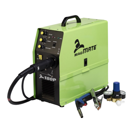
Ensure that the torch is screwed in tight. The MagMate 180P is designed for D200 (5 kg) spools maximum. Fit the spool onto the spool holder and ensure that the locating nut is replaced and tightened. -
Page 21: Periodic Maintenance
The working environment or amount of use the machine receives should be taken into consideration when planning maintenance frequency of your MagMate welder. Preventative maintenance will ensure trouble free welding and increase the life of the machine and its consumables. -
Page 22: Warranty Information
9.0 Warranty Information 9.1 Terms of Warranty 9.3 Warranty Period ™ The MagMate machine has a limited warranty The warranty is valid for 18 months from date that covers manufacturing and material defects of purchase provided the machine is used within only. -
Page 23: Recommended Safety Guidelines
10.0 Recommended Safety Guidelines Some safety precautions BOC recommends are as follows: • Repair or replace defective cables immediately. • Keep fire extinguishing equipment at a handy location in the shop. • Never watch the arc except through lenses of the correct shade. •... - Page 24 For more information on MagMate products or service, call the BOC Customer Service Centre on: AUS TRAL IA 131 262 Email: Contact@boc.com Website: www.boc.com.au NEW Z E ALAN D 0800 111 333 Email: customer-service-nz@boc.com Website: www.boc.co.nz ™ MagMate is distributed by:...
Need help?
Do you have a question about the 180P and is the answer not in the manual?
Questions and answers