Advertisement
Quick Links
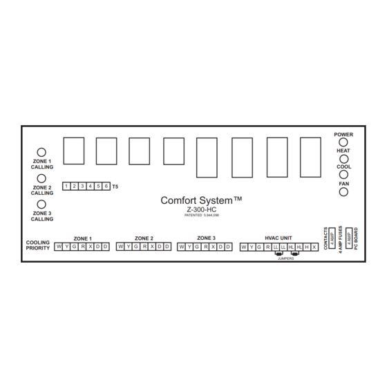
Installation Instructions for Z-300-HC Zone Control Panel
ZONE 1
CALLING
1
2
3
4
5
6
T5
ZONE 2
CALLING
ZONE 3
CALLING
ZONE 1
COOLING
W Y G
R X D D
PRIORITY
W Y G
R X
D
D
D
W Y G
R C
SINGLE STAGE
HEAT / COOL
DAMPER MOTOR
THERMOSTAT
0.36 AMPS 10 VA
Installation Notes:
To install the panel, first slide the PC
board out of its base and screw the
base to a flat surface next to the
HVAC equipment. The PC board
should be reinstalled by centering it
over the base and pushing firmly.
Connect only 24 Vac to Control
Panel.
The control panel requires a
separate 24 Volt transformer.
No special wire is required.
The thermostat and motorized
dampers may be located up to 300
feet from the control panel when
using 18 gauge thermostat wire.
The left fuse (4 Amp) protects the
relay contacts. The right fuse (4
Amp) protects the printed circuit
board.
Zone dampers are powered
closed / spring return open.
If condensing unit is not equipped
with short cycle protection timer,
(TD-5) should be installed.
The two wires from the condensing
Zone Control Made Simple™
Comfort System
Heat / Cool Auto Changeover - Cooling Priority
Comfort System™
Z-300-HC
PATENTED 5,944,098
ZONE 2
ZONE 3
W Y G
R X D D
W Y G
R X D D
WIRE THE SAME
AS ZONE 1
unit should be connected to the 'Y'
and transformer common terminals
at the furnace.
The low limit (FS-38) should be
wired to the 'LL' terminals on the
panel (remove jumper). The
compressor will shut off when low
limit trips out.
The high limit (HL-170) should be
wired to the 'HL' terminals on the
panel (remove jumper). The furnace
will shut off when high limit trips out.
A 40 VA transformer will power the
panel and up to four (4) dampers.
A 75 VA transformer will power the
panel and up to seven (7) dampers.
Up to three (3) dampers can be
connected in parallel. A total of no
more than seven (7) dampers may
be connected to the system. A
system may be a single panel or
multiple panels.
If more than three (3) zones are
required, two additional panels can
be used to control up to a total of
nine (9) zones. T5 terminal strip is
used only when more than three
zones are required.
HVAC UNIT
LL LL HL HL
W Y G
R
H X
JUMPERS
W Y G R
LL LL
HL HL
W Y G
R C
HVAC UNIT
LOW
120/24 VAC
TERMINAL
HIGH
LIMIT
TRANSFORMER
STRIP
LIMIT
Label the dampers, damper wires
and thermostat wires with the zone
number and the area they serve.
Specifications:
Panel Dimensions:
Height:
Width: 10.0 inches
Depth:
Mounting:
2 back plate screws
Operating Ambient Temperature:
-20° to 160° F
Power Supply:
24 Vac 40VA / 75 VA transformer
Terminal Designations:
W =
Y =
G =
R =
X =
D =
LL =
HL =
H =
X =
5418 Elmwood Avenue, Indianapolis, IN 46203-6025
Toll Free: 888.652.9663 Fax: 317.227.1034
www.jacksonsystems.com
TM
POWER
FAN LED INDICATES
HEAT
WHEN A
THERMOSTAT IS
CALLING FOR FAN.
COOL
FAN
WHEN GREEN ZONE
LEDS ARE ON, THOSE
ZONES ARE CALLING
FOR HEATING OR COOLING
H X
5.0 inches
2.0 inches
Heat
Cool
Fan
Hot 24 Volt
Common
Damper
Freeze Stat
High Limit
Hot 24 Volt
Ground or Common
Advertisement

Subscribe to Our Youtube Channel
Related Manuals for Jackson Systems Comfort System Z-300-HC


Summary of Contents for Jackson Systems Comfort System Z-300-HC
- Page 1 Comfort System Installation Instructions for Z-300-HC Zone Control Panel Heat / Cool Auto Changeover - Cooling Priority POWER FAN LED INDICATES HEAT WHEN A THERMOSTAT IS ZONE 1 CALLING FOR FAN. CALLING COOL ZONE 2 WHEN GREEN ZONE CALLING LEDS ARE ON, THOSE Comfort System™...
- Page 2 Comfort System Installation Instructions for Z-300-HC Zone Control Panel Heat / Cool Auto Changeover - Cooling Priority Sequence of Operation: Typical System Layout Comfort System™ is a residential / light commercial zone control system that allows a single HVAC unit to have up to three separate zones (nine if three panels are connected ZONE 2 together).
Need help?
Do you have a question about the Comfort System Z-300-HC and is the answer not in the manual?
Questions and answers