
Summary of Contents for Ryobi RA-NF90-K
- Page 1 RA-NF90-K AIRWAVE AIR FRAMING NAILER OPERATOR'S MANUAL ORIGINAL INSTRUCTIONS Important! It is essential you read the instructions in this manual before starting and operating this machine.
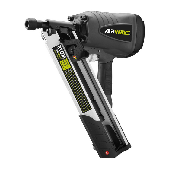
- Page 2 DESCRIPTION 1. Nitto style coupler 12. Hex screw 2. Exhaust cap 13. Hex key 3. Air supply 14. Screw hanger 4. Nails 15. Wrench 5. Pusher 16. No-mar pad 6. Magazine 7. Trigger 8. Depth adjustment knob 9. Stopper 10. Flat blade screwdriver 11.
- Page 3 Fig. 8 Fig. 9 Fig. 10 Fig. 11 Fig. 12 Fig. 13 Quick Quick connector connector Lubricator Filter Tool compressor Cut-off valve Quick Quick coupler coupler Regulator Air hose (0-8.5 bar) Fig. 14...
-
Page 4: General Safety Rules
and avoiding awkward or off-balanced postures. The GENERAL SAFETY RULES operator should change posture during extended For multiple hazards, read and understand the safety tasks, which can help avoid discomfort and fatigue. instructions before installing, operating, repairing, If the operator experiences symptoms, such as maintaining, changing accessories on, or working persistent or recurring discomfort, pain, throbbing, near, the air tool. -
Page 5: Additional Safety Instructions For Pneumatic Power Tools
hand-held power tools – Part 11: Fastener driving tools Stands for mounting the fastener driving tools to a support, for example to a work table, shall be designed and constructed by the stand manufacturer in such This value is a tool-related characteristic value and does a way that the fastener driving tools can be safely fixed for the intended use, thus for example avoiding damage, distortion and displacement. -
Page 6: Residual Risks
against a work piece, These tools are marked with an SYMBOLS inverted triangle behind the serial number and are not permitted for use without an effective safety yoke. A safety yoke is not required on fastener driving tools Safety alert which accelerate the heaviest usable fasteners to a free flight velocity below an admissible risk of injury. -
Page 7: Intended Use
Carefully remove the tool and any accessories from NOISE AND VIBRATION the box. Make sure that all items listed in the packing list are included. Noise according to EN 12549:1999 and EN ISO 4871 A-weighted sound WARNING L PA PA =2.5 dB pressure level Do not use this product if it is not completely assembled Sound power level... -
Page 8: Adjusting The Exhaust
The pad can be removed by pulling it down and away from WARNING Always wear safety goggles or safety glasses with side the safety yoke and push up. shields when operating tools. Failure to do so could ADJUSTING THE EXHAUST result in objects being thrown into your eyes resulting in possible serious injury. - Page 9 WARNING WARNING Always use a coupling that discharges all the Use only the fasteners recommended for use with this tool. The use of any other fasteners can result in tool hose coupling is disconnected. Using a coupling that malfunction, leading to serious injuries. does not discharge the compressed air could cause unintended operation and serious personal injury.
- Page 10 safety yoke of the tool onto the work surface. needed, use the drive depth adjustment on the tool. 3. Push the tool against the work surface to depress the DRIVE DEPTH ADJUSTMENT safety yoke. 4. Squeeze the trigger to drive a fastener. 5.
-
Page 11: General Maintenance
4. Remove the jammed fastener. operation. We recommend the use of air tool lubricant or 5. Reconnect the tool to the air supply. lubricant. 6. Reinstall fasteners. ATTACHING THE SCREW HANGER WARNING Do not store tools in a cold weather environment to 1. - Page 12 WARNING Do not use any attachments or accessories not recommended by the manufacturer of this tool. The use of attachments or accessories not recommended can result in serious personal injury. LUBRICATION the product in sustained operation. The in-line lubricator Proper adjustment of the in-line lubricator is performed by placing a sheet of paper next to the exhaust ports and actuate the tool 10 - 15 times without fasteners loaded.
-
Page 13: Troubleshooting
TROUBLESHOOTING PROBLEM CAUSE POSSIBLE SOLUTION Loose screws. Tighten screws. Air leak near the top of the tool or in the trigger area. Worn or damaged O-rings or seals. Install overhaul kit. Loose screws. Tighten screws. Air leak near the bottom of the tool. -
Page 14: Parts List
PARTS LIST No. Description Description Description No. Description Bolt Gun body Adjustment rod Locknut M6 O-ring 62 x 1.8 Adjustment bolt M6 Pusher seat Drive guide Adjustment nut M6 Pusher spring Spring washer D8 Roll pin 3 x 20 Pusher Spring Hex socket bolt M8 x 25 Roll pin 2.5 X 22... - Page 15 Techtronic Industries (Australia) Pty. Ltd. Level 1, 660 Doncaster Road Doncaster, VIC 3108, Australia Techtronic Industries New Zealand Ltd. 18-26 Amelia Earhart Avenue Mangere, Auckland 2022, New Zealand...
Need help?
Do you have a question about the RA-NF90-K and is the answer not in the manual?
Questions and answers