Table of Contents
Advertisement
Quick Links
Download this manual
See also:
Operating Manual
Advertisement
Chapters
Table of Contents

Related Manuals for Koden CVG-200

Summary of Contents for Koden CVG-200
-
Page 2: Declaration Of Conformity
Declaration of Conformity (As required by Article 7 (1) of Directive 89/336/EEC) Declares under his sole responsibility that the produced Plotter/Sounder manufactured by Koden Electronics Co., Ltd. 5278 Uenohara, Uenohara Citv Yamanashi-Ken 409-0112, Japan Telephone +81 554 20 5865 Telefax +81 554 20 5880... - Page 3 Koden Electronics Co. Ltd. The technical descriptions contained in this publication are subject to change without notice. KODEN assumes no responsibility for any errors, incidentals or consequential damages caused by misinterpretation of the descriptions contained in this...
-
Page 4: Getting Started
CVG-200 Preface Getting Started Please guard against losing or damaging this text. In the event of reselling or handing over this device to someone else, please be Using the Main sure to include this manual to the new owner. Text In addition, it is advisable to have this text nearby while this device is in operation. - Page 5 Preface CVG-200 Types of Operational Warnings This device aids in navigation. For decision making in sound navigation, Warning please be sure to use other widely used resources in addition to this device: land maps, sea maps, GPS devices, landmarks, water depth, obstacles, and other devices.
- Page 6 CVG-200 Preface Types of Cautions During Maintenance Be certain to turn off your boat’s power Warning Carelessly switching on the power during inspection may result in electrical shock. In order to prevent such accidents, be sure to switch off the power of this device as well as the power of the boat.
-
Page 7: Standard Equipment List
Scope of this manual This manual contains general information as well as system composition, installation, operation and maintenance of the CVG-200 Plotter/Sounder Structure of this manual This manual is divided into sections according to the contents as outlined below. This allows for the overview of the entire manual as well accessing detailed information for your specific requirement. - Page 8 CVG-200 Preface Cable Routing and Connections Display Installation Internal Connections of The System Post-installation Inspections Chapter 5: Basic Operations Name and Function of Parts Displaying the Images Plotter Screen Operation of Sounder Display Chapter 6: Using the Menu Menu Functions...
- Page 9 CVG-200 Chapter 1 General Information Chapter 1 General Information Page No. About GPS..................................... 1.1.1 GPS Satellite Arrangement ....................1.1.2 GPS Organization ....................1.1.3 On Proper Use Outline of The Equipment ................. Applicable Standards ................Software Type Name.................. Equipment Composition ................
-
Page 10: About Gp
CVG-200 Chapter 1 General Information Chapter 1 General Information About GPS 1.1.1 GPS Satellite Arrangement GPS (Global Positioning System) is a navigation system using 24 satellites (21 plus 3 in service) orbiting above the earth once every 11 hours 58 minutes at an altitude of about 20,000 km. -
Page 11: Outline Of The Equipment
General Information 1.2 Outline of The Equipment The CVG-200 is a plotter/sounder device, consists of a plotter unit with a GPS sensor and a sounder equipped with transmission/receiver. The available power output is two kinds, 600W and 1kW. It carries two frequencies, 50 kHz and 200 kHz. -
Page 12: General Information
ST-80-1 Water temperature sensor Fuse10A Cable CW-838-0.5M gland ・Transducer TD-501C Ship side ・Rectifier Metal PS-006 fittings ・Transducer 500T-2B VV-2D8-3M /500T-3B /501T-3B External buzzer 100/115VAC 10.8~ 200/230VAC 31.2VDC :Standard :Option :User Interface Figure 1.1 Configuration of CVG-200 93132801-00 1- 3... - Page 13 CVG-200 Chapter 2 Equipment Composition Chapter 2 Equipment Composition Page No. 2.1 Standard Equipment List ................2-1 2.2 Spare Parts List ....................2-1 2.3 Option Items List ..................2-1 2.4 Transducers....................2-2 93132801-00 Contents...
-
Page 14: Option Items List
CVG-200 Chapter 2 Equipment Composition Chapter 2 Equipment Composition 2.1 Standard Equipment List Weight/ Item name Type name Remarks Q’ty Length Receiver unit CVG-200 With base mount and 6.8 kg hard cover DC Power cable CW-253-2M For Receiver unit Transducer... - Page 15 2.5kg CG-3 For FRP hull 0.9kg CG-16 For FRP /wooden hull 1.0kg CG-19 Metal fittings SL-2 2.5kg Stainless,1 1/2 inch Operation CVG-200. O/M.E English manual 2.4 Transducers Output Type name Frequency Weight TD-500T-2B 50/200 kHz 0.7kg 600W TD-500T-3B 50/200 kHz 1.5kg...
-
Page 16: Table Of Contents
CVG-200 Chapter 3 Specifications Chapter 3 Specifications Page No. 3.1 Specifications ....................3-1 3.1.1General Specifications ....................3-1 3.1.2 Specifications of Sounder....................3-1 ................3.1.3 Specifications of Plotter 3.2 Serial Data....................3-3 3.3 Power Requirements................... 3-4 3.4 Environmental Conditions................3-4 3.5 External Dimensions and Weight............... 3-4... -
Page 17: Specifications
CVG-200 Chapter 3 Specifications Chapter 3 Specifications 3.1 Specifications Specifications are subject to change without notice. 3.1.1General Specifications Display 10.4 inch color TFT LCD(480 x 640 dots) Display mode Plotter Echo Sounder (Single frequency normal image/Single frequency normal/zoom images/Dual frequency dual images) - Page 18 Chapter 3 CVG-200 Specifications ・High/Low frequency Picture mode N: Normal (incl. SHIFT) Single display Dual display Z1: (Zoom1) Bottom Lock (Zoom2) Bottom Discrimination Z3: Bottom Zoom ・High/Low freq. : Normal ・High/Low freq.: Bottom Zoom BZ: Bottom Zoom (H): High frequency...
-
Page 19: Specifications Of Plotter
CVG-200 Chapter 3 Specifications 3.1.3 Specifications of Plotter Map mode Mercator projection Display mode North-up, East-up, South-up, West-up, Course-up (Waypoint), Head-up and Centered North-up Zooming range 0.01 to 3,600 nm(0.02 to 6,600 km) around Equator Effective map creation area Below the latitude 75 degree... -
Page 20: Serial Data
Chapter 3 CVG-200 Specifications 3.2 Serial Data Input data Type: NMEA0183 Ver.2.0/1.5 Sentence: GPS/DGPS(J5) HDT, GGA, GLL, MSK, MSS, PKODA, PKODG, RMC, VTG, CH1(J2), CH2(J6) HDT, MTW, TLL, TTM Output data Type: NMEA0183 Ver,2.0 Sentence: CH1(J2) APB, BWC, GGA, GLL, GTD, RMB, VTG, WPL, XTE, ZDA... -
Page 21: Power Requirements
(3) Water proof IPX5(Water jet proof) 3.5 External Dimensions and Weight External dimensions: Width x Depth x Height unit (mm) Dimensions: 380 x 138 x 340 Weight : 6.8 Kg Dimensions: 29.5 Figure 3.1 External dimensions of CVG-200 93132801-00... - Page 22 CVG-200 Chapter 4 Installation Chapter 4 Installation Page No. 4.1 Installation Consideration ................4-1 4.2 Unpacking of The Box ..................4-1 4.3 Inspection of The Equipment .................4-1 4.4 Proper Location for Setup ................4-1 4.5 Cable Routing and Connections ..............4-1 4.6 Display Installation..................4-2 4.6.1 Table mounting........................
-
Page 23: Installation Consideration
Installation Chapter 4 Installation 4.1 Installation Considerations Qualified service technicians should perform the installation of CVG-200 that comprises of the following operations: (1) Unpacking each component of the system. (2) Inspection of the exterior of each component unit and accessory. -
Page 24: Display Installation
Chapter4 CVG-200 Installation (2) The display unit should be grounded to the hull with a wire cut as short as possible. We recommend using a wide and heavy copper braid or plate to be connected to a grounding stud at the rear of the display unit. -
Page 25: Flush Mounting
CVG-200 Chapter 4 Installation Unit in mm Figure 4.2 Servicing Access space required 4.6.2 Flush mounting (1) Cut a rectangle opening. (Refer to Figure 4.4) (2) Loosen two (2) fixing bolts that fasten the display unit on to the mounting bracket. - Page 26 Chapter4 CVG-200 Installation Fixing holes for M4 screw Figure 4.4 Dimensions of opening and fixing holes for flush mounting 93132801-00...
-
Page 27: Inter-Connections Of The System
CVG-200 Chapter 4 Installation 4.7 Inter-connections of The System As pictured in Figure 4.5, connect the various cables to their prescribed locations on the rear panel of the display unit. NMEA0183 Marine Radar with ATA MDC-721/741/740 CW-381-5M MDC-1541/1540/1560/1510 MDC-1021/1041/1040 MDC-1121/1141/1140... -
Page 28: Preparation Of Dc Power Cable (Cw-253-2M)
Chapter4 CVG-200 Installation 4.7.1 Preparation of DC Power cable (CW-253-2M) White To Display unit Black Gray Ext. buzz. out Green Ext. buzz. out 4.7.2 Connecting the Transducer and Temperature/Speed Sensor The connectors for TD-500T-2B/500T-3B/501T-3B transducer are equipped with 8-pin water resistant connector (LTW). - Page 29 CVG-200 Chapter 4 Installation Transducer Connection Table Transducer Cable Transducer 2 lead shield 2 lead shield TD-500T-2 TD-501T-3 wire number wire color TD-500T-3 TD-501C orange black shield shield shield white white white 4.7.2.2 Connecting Water Temperature/Speed Sensors Solder the wire protruding from TD-500T-2B/500T-3B or CW-840-0.3M, while referring to the table on connecting water temperature/speed sensors.
-
Page 30: Layouts Of The Pin Connections
③ ⑤Frame GND 4.8 Post-installation Inspections Before you turn the CVG-200 on, check the following points to make sure the CVG-200 operates properly: (1) Is the ship’s supply voltage and current within the proper range? Input voltage: 10.8 to 31.2 VDC at POWER connector... - Page 31 CVG-200 Chapter Basic Operation Chapter 5 Basic Operation Page No. 5.1 Name and Function of Parts................5-1 5.1.1 Control Panel ........................... 5-1 5.1.2 Display Unit..........................5-2 5.2 Displaying the Image ..................5-3 5.2.1 Power On/Off ........................... 5-3 5.2.2 Brightness Setting ........................5-3 5.2.3 Choosing the Display.......................
- Page 32 Chapter 5 CVG-200 Basic Operation 5.3.10.4 Resetting the Route Start Point..................5-21 5.3.10.5 Deleting Routes......................5-21 5.3.11 Entering Values and Comments................... 5-22 5.3.12 Object Information........................ 5-23 5.4 Operation of Sounder Display ..............5-25 5.4.1 Sounder Display Options ....................... 5-25 5.4.1.1 About The Modes ......................5-25 5.4.1.2 Regarding Display Images ....................
-
Page 33: Name And Function Of Parts
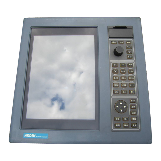
CVG-200 Chapter 5 Basic Operation Chapter 5: Basic Operation 5.1Name and Function of Parts 5.1.1 Control Panel Slot for Optional Memory Card On/Off and setting switch for the SHIFT function. Settings and changes carried out by the knob. On/Off and setting switch for the VRM function. -
Page 34: Basic Operation
Chapter 5 CVG-200 Basic Operation 5.1.2 Display Unit Route Boat Bearings Speed M A R K ° ° 18.6kt ° ° ° ° 30’ 26’ 28’ Mark Color 06’ Track Color Plotter Screen Map Scale 04’ 0.5nm Time mark (1 min increments) 高... -
Page 35: Displaying The Image
Authentic navigation charts shall be used when navigation judgment CVG-200 required. Also, when the power is on, KODEN ELECTRONICS CO., LTD KMC-92 VerX.X(WGS-84) pressing turns the power off. Backup Battery cell System test This display appears Caution display... -
Page 36: Plotter Screen
Chapter 5 CVG-200 Basic Operation 5.3 Plotter Screen 5.3.1 Discovering Current Position The current position of the user’s boat is displayed through the latitude and longitude (appearing in the upper left hand corner of the display) or by the LOP. -
Page 37: Moving The Display With The Cross Cursor
CVG-200 Chapter 5 Basic Operation 5.3.3 Moving the Display with the Cross Cursor Using the cross cursor allows for free movement of the screen. Push and the cross cursor will appear on the plotter screen. Push the directional key and the cross cursor will move in the same direction. -
Page 38: Display Of Distance Between Two Points And Bearings
Chapter 5 CVG-200 Basic Operation 5.3.4 Display of Distance between Two Points and Bearings Using the cross cursor enables the user to calculate the distance between two points as well as bearing. Push and the cross cursor shall appear on the plotter. -
Page 39: Altering Scale Of Map Display
CVG-200 Chapter 5 Basic Operation 5.3.5 Altering Scale of Map Display 5.3.5.1 Magnification of Map Display Press and the user can magnify the map display. Normally, magnification takes place with the boat being in the center. When the cross cursor is displayed, rather than the boat being the center-point, the cross cursor is taken as the center-point. -
Page 40: Settings Of Tracks
Chapter 5 CVG-200 Basic Operation 5.3.6 Settings of Tracks 5.3.6.1 Display of Tracks Press recording of tracks can be activated or deactivated. Activating track recording causes “Turns on a ship’s track display.” to appear on the display. The number of tracks shall appear on the lower right-hand corner of the plotter. -
Page 41: Track Color Settings
CVG-200 Chapter 5 Basic Operation 5.3.6.2 Track Color Settings There are 3 types of Settings for Track Color: “Normal”, “Sounding RESP”, and “W_Temp RESP.” Normal: Manually choose from 7 colors in this setting. Sounding RESP: Based on the depth of the water, the color of the tracks shall be automatically colored. -
Page 42: Deleting Tracks
Chapter 5 CVG-200 Basic Operation 5.3.6.3 Deleting Tracks Deleting tracks depends on the state of the cross cursor. Cross Cursor not displayed……….Deletion based on color Cross Cursor displayed……….Deletion based on specified range 5.3.6.3.1 Procedure for Color-Based Track Deletion Tr a c k E r a s e... -
Page 43: Mark Settings
CVG-200 Chapter 5 Basic Operation 5.3.7 Mark Settings 5.3.7.1 Mark Color Settings M a r k C o l o r Press and the mark color setting window shall appear. Cursor Use the directional keys to specify the mark color: Press to choose the color specified by the cursor. -
Page 44: Mark Deletion
Chapter 5 CVG-200 Basic Operation 5.3.7.3 Mark Deletion Mark deletion depends on the state of the cross cursor. Cross Cursor not displayed……….Deletion based on color and shape of mark Cross Cursor displayed……….Deletion by Cross Cursor 5.3.7.3.1 Deletion Based on Color and Shape of Mark... -
Page 45: Storing Events
CVG-200 Chapter 5 Basic Operation 5.3.7.4 Storing Events Storing events may be labeled as Mark 00 to Mark 99. This information can be displayed on the top of the screen. The number of the mark being reported on can be changed. -
Page 46: Setting Waypoints
Chapter 5 CVG-200 Basic Operation 5.3.8 Setting Waypoints To set waypoints, the user can use a registered mark or move the cursor to the destination. 5.3.8.1 Setting a Registered Mark as Waypoint In Waypoint mode, a specified point becomes the waypoint. In the operation shown below, Waypoint mode begins with using the current position as a reference point. -
Page 47: Using The Cursor To Register Waypoints
CVG-200 Chapter 5 Basic Operation 5.3.8.2 Using the Cursor to Register Waypoints Confirm that the cursor appears on the screen. (2) Press (3) Use the key to move the cross cursor to your designated waypoint. Should a mark enter the circular marks of the cross cursor, that mark shall be taken to be the waypoint. -
Page 48: Resetting The Starting Point Of The Waypoint
Chapter 5 CVG-200 Basic Operation 5.3.8.4 Resetting the Starting Point of the Waypoint At the start point of the waypoint mode, the current position is taken to be the waypoint. The procedure below allows for the establishment of a new starting point. -
Page 49: Pob Settings
CVG-200 Chapter 5 Basic Operation 5.3.9 POB Settings This is an emergency event function to mark the location of an accident such as a person overboard. 5.3.9.1 PCB Position Settings Press and the POB position shall be set at the current position. -
Page 50: Route Setting
Chapter 5 CVG-200 Basic Operation 5.3.10 Route Setting In order to determine settings for the route mode, a pre-registered route is required. Routes may be registered by the following procedure: → “Plotter” → “Route” → “Routing” → “Chose creation method” → [Set] →... - Page 51 CVG-200 Chapter 5 Basic Operation The turn-around point of the route (shown by the flag) depends upon the route being either a forward route or a return route. The boat’s initial turn-around point is designated by a flag. Press to set the route. If no route is registered, nothing will occur even if the user presses the key.
-
Page 52: Setting Route By Cross Cursor
Chapter 5 CVG-200 Basic Operation 5.3.10.2 Setting Route by Cross Cursor R o u t e E x e c u t e Route No With the cross cursor displayed, press Comment bring up the route window pictured to the right. -
Page 53: Resetting The Route Start Point
CVG-200 Chapter 5 Basic Operation 5.3.10.4 Resetting the Route Start Point With the route mode in effect, press and the route operation window shall appear. With the route operation window visible, press to designate the current position as the new start point. -
Page 54: Entering Values And Comments
Chapter 5 CVG-200 Basic Operation 5.3.11 Entering Values and Comments The user can enter comments (numbers and letters) through a specified, related plotter menu. The keys corresponding to various characters are arranged as shown below: 2→D→E→F 3→G→H→I 1→A→B→C 5→M→N→O 4→J→K→L 6→P→Q→R... -
Page 55: Object Information
CVG-200 Chapter 5 Basic Operation 5.3.12 Object Information Using this function, the information of objects shown on the chart can be displayed. Available information differs depending on whether the cross cursor is displayed or not as follows: With the cross cursor OFF: The object information around the ship is shown in the OBJECT INFORMATION window. - Page 56 Chapter 5 CVG-200 Basic Operation (3) To view the details of each item shown, press the ENT key. (4) When the content is in overleaf, an up and down arrow keys appear on the top and the bottom edge of the page. To move to other page, press the up or down.
-
Page 57: Operation Of Sounder Display
CVG-200 Chapter 5 Basic Operation 5.4 Operation of Sounder Display DISP Push to display the Sounder Display. 5.4.1 Sounder Display Options Push MODE to bring up the Mode menus. High Frequency Mode Low Frequency Mode High and Low Frequency Mode... -
Page 58: Regarding Display Images
Chapter 5 CVG-200 Basic Operation 5.4.1.2 Regarding Display Images (1) Normal Displays from the start point of the image to the limit of the range. Generally, the bottom of the Image Start Point ship is the designated starting point. Utilizing Range the various functions (such as Shift, Draft, etc.) -
Page 59: Procedures For The Sounder Display
CVG-200 Chapter 5 Basic Operation (5) Part Expansion Rather than using the sea bottom as the reference point, a mid-water Magnification Start Point is designated and the region below is Magnification Start Point magnified. Zoom range The zoom range is set through the value assigned in the menu. The setting chosen shall be shared by all expansion images. -
Page 60: Procedure For Displaying Magnified High Frequencies
Chapter 5 CVG-200 Basic Operation 5.4.1.3.3 Procedure for Displaying Magnified High Frequencies High Frequency High Frequency (Normal) (Magnified) MODE (1) Display High Frequency Mode using High 67.0 (2) Using the control knob, the user can choose: 50.0 Bottom Fixation Expansion, Bottom Quality Expansion, Bottom Part Expansion, and Part Expansion. -
Page 61: Range(Sounding Range)Selection
CVG-200 Chapter 5 Basic Operation 5.4.2 Range(Sounding Range)Selection Factory Preset Ranges are as follows: Range m/J.fm /fm/I.fm 1000 1200 1600 3600 4000 RANGE RANGE keys can be used to adjust the Range values. Simultaneously, the screen depicted below will display the Range values. -
Page 62: Adjustment Of Gain And Stc
Chapter 5 CVG-200 Basic Operation 5.4.3 Adjustment of Gain and STC GAIN Push to bring up the image adjustment menu. High Frequency Low Frequency Current Frequency Setting Gain Gain Cursor(highlighted) Gain value(bar display) Gain value(numerical) Enhance Enhance Enhancement value(bar display)... - Page 63 CVG-200 Chapter 5 Basic Operation When automatic gain is in operation, pressing GAIN will activate the automatic gain correction in the Adjustment Menu. High Frequency Low Frequency Auto Gain Correction Auto Gain Correction Auto Gain Correction (bar display) -3.0 -3.0...
- Page 64 Chapter 5 CVG-200 Basic Operation (a) STC Depth STC Amplitude The graph to the right depicts the change in the (Large) image below. STC Amplitude is kept at a constant. A :Since the STC Depth value is too small, only drifting material is removed from the image.
-
Page 65: Operation Of The [Shift] Key
CVG-200 Chapter 5 Basic Operation 5.4.4 Operation of the [Shift] Key There exist 2 kinds of shifts: “Fix Shift” and “Auto Shift”. Fix Shift: From Pre-determined depth(Shift start depth), the range is set and displayed. Auto Shift: Should there be a sudden change is depth of the bottom engaging the Auto Shift ensures that 30-90% of the scope of the sea bottom is displayed at all times. -
Page 66: Auto Shift Settings
Chapter 5 CVG-200 Basic Operation 5.4.4.2 Auto Shift Settings Displaying the Auto Shift function requires the following procedure beforehand. The procedure is as follows: →“Sounder”→“Sounder Menu”→“Auto Setting”→[Shift]→ MENU MENU SHIFT Push , and the Shift menu appears. Shift Shift Auto Shift Mode... -
Page 67: Operation Of Variable Range Markers (Vrm)
CVG-200 Chapter 5 Basic Operation 5.4.5 Operation of Variable Range Markers (VRM) The Variable Range Markers (VRM) enable for the operation of the Sounder screen. The VRM allow for moving up and down within the screen. Matching up the schools of fish with the depth markers indicate their depth. -
Page 68: Combined Imaging
Chapter 5 CVG-200 Basic Operation 5.4.5.2 Combined Imaging 5.4.5.2.1 Vertical Partitioning (1) Dual Frequency mode High Push 43.0 Turn over the numerical value displayed. The VRM is displayed across the entire screen. Move up or down using the control knob. - Page 69 CVG-200 Chapter 5 Basic Operation (2) Normal/ Expansion mode Push High 67.0 The numerical value turns over. A VRM appears on one side of the partitioned screen. Move up or down using the control knob. Move up Move down As the VRM moves, the numerical value displayed changes accordingly.
-
Page 70: Horizontal Partitioning
Chapter 5 CVG-200 Basic Operation 5.4.5.2.2 Horizontal Partitioning (1)Dual Frequency mode High Push 95.0 Numerical value display turns over. The VRM Move from upper screen stretches across the entire width of the screen. to lower screen Move up or down using the control knob. -
Page 71: Setting Positions For Part Expansion Mode
CVG-200 Chapter 5 Basic Operation 5.4.6 Setting Positions for Part Expansion mode 5.4.6.1 Vertical Partitioning (1) Push and select Part Expansion of High (or Low) Frequency Mode. MODE (Refer to Sounder Imaging Display Procedure, section 5.4.1.3.) (2) Set the zoom range. -
Page 72: Horizontal Partitioning
Chapter 5 CVG-200 Basic Operation 5.4.6.2 Horizontal Partitioning (1) Push and select Part Expansion of High (or Low) Frequency Mode. MODE (Refer to Sounder Imaging Display Procedure, section 5.4.1.3.) (2) Set the zoom range. (Please refer to Imaging, section 5.4.1.2.) (3) Push and turn over the numerical display of the Green Marker. - Page 73 CVG-200 Chapter 6 Using the Menu Chapter 6 Chapter 6 Using the Menu Page No. 6.1 Menu functions....................6-1 6.1.1 Menu Operation........................6-1 6.1.2 Choosing Menus........................6-2 6.1.3 Menu Table ..........................6-3 6.1.3.1 Sounder Menu ........................6-3 6.1.3.2 Plotter Menu Functions ...................... 6-5 6.1.3.3 ETC.
- Page 74 Chapter 6 CVG-200 Using the Menu 6.2.7 Bottom Detection Adjust......................6-21 6.2.7.1 High Frequency, Low Frequency..................6-21 6.3 Plotter Menu ....................6-22 6.3.1 Mark Block Number ....................... 6-22 6.3.2 Display Settings ........................6-22 6.3.2.1 Position Data Display ....................... 6-22 ..........................6-22 6.3.2.1.1 L / L...
- Page 75 CVG-200 Chapter 6 Using the Menu ....................6-32 6.3.5.3.1.1 Waypoint Movement ....................6-32 6.3.5.3.1.2 Waypoint Addition ...................... 6-33 6.3.5.3.1.3 Waypoint Erase ..........................6-33 6.3.5.3.2 Value ....................6-33 6.3.5.3.2.1 Waypoint Movement ....................6-33 6.3.5.3.2.2 Waypoint Addition ...................... 6-34 6.3.5.3.2.3 Waypoint Erase ......................
- Page 76 6.3.16.6 Base Point ........................6-44 6.3.16.7 Altering Settings of Parallel Line Drawings without Menus ..........6-44 6.4 Settings of Other Menus (ETC)..............6-45 6.4.1 GPS/DGPS setting (KODEN products only)................6-45 6.4.2 GPS Monitor .......................... 6-45 6.4.3 User C-Card........................... 6-45 6.4.3.1 Store ..........................6-46 .........................
-
Page 77: Chapter 6 Using The Menu
CVG-200 Chapter 6 Using the Menu Chapter 6 Using the Menu 6.1 Menu functions The main menu has three categories: Sounder, Plotter, and “etc.” (others). From these categories, other sub-menus and categories shall appear. These sub-menus are explained from page 6-3 onward. -
Page 78: Choosing Menus
Chapter 6 CVG-200 Using the Menu 6.1.2 Choosing Menus [ Example of Choosing a Menu ] The cursor moves down corresponding to the number of times the down key is pressed. The cursor moves up corresponding The sub-menu of the... -
Page 79: Menu Table
CVG-200 Chapter 6 Using the Menu 6.1.3 Menu Table 6.1.3.1 Sounder Menu Sounder Menu Setting Menu Setting Range Transmission Pulse Width (H) Super short, Short, Middle, Long Pulse Width (L) Super short, Short, Middle, Long Output Normal, Low 1 to 10... - Page 80 Chapter 6 CVG-200 Using the Menu Sounder Menu Menu Setting Range Depth range 1 Refer to 6.2.5.1 Depth range preset 〃 Depth range 2 〃 Depth range 3 〃 Depth range 4 〃 Depth range 5 〃 Depth range 6 〃...
-
Page 81: Plotter Menu Functions
CVG-200 Chapter 6 Using the Menu 6.1.3.2 Plotter Menu Functions Plotter Menu Sub Menu 1 Sub Menu 2 Setting Range Mark Block 00000, 00100, 01000, 02000, 03000, 04000, Number 05000, 06000, 07000, 08000 Display Setting Position data display LORAN C... - Page 82 Chapter 6 CVG-200 Using the Menu Plotter Menu Sub Menu 1 Sub Menu 2 Setting Range Edit Mark Edit Transfer Delete Operation of blocks Display of blocks Transfer of blocks Erase of blocks Route Routing Cursor Value Route erase Cursor...
- Page 83 CVG-200 Chapter 6 Using the Menu Plotter Menu Sub Menu 1 Sub Menu 2 Setting Range System Setting Distance/Speed nm, kt km, km/h Plot interval Time, Distance Time interval 1, 2, 5, 10, 20, 30, 120, 300, (second) Distance interval 0.01, 0.02, 0.05,...
- Page 84 Chapter 6 CVG-200 Using the Menu Plotter Menu Sub Menu 1 Sub Menu 2 Setting Range 0 ゚ 00.000N to Start position Geodesic Line 90 ゚ 00.000N, 0 ゚ 00.000S to 90 ゚ 00.000S 0 ゚ 00.000E to 180 ゚ 00.000E, 0 ゚...
-
Page 85: Etc. Menu
CVG-200 Chapter 6 Using the Menu 6.1.3.3 ETC. Menu etc. Menu Sub Menu 1 Sub Menu 2 Setting Range GPS/DGPS Setting Datum TOKYO, WGS-84 Average 1 to 3 DGPS mode OFF, BEACON, SBAS Beacon AUTO, MANUAL select Frequency 283.5 to 325.0... - Page 86 Chapter 6 CVG-200 Using the Menu etc Menu Sub Menu 1 Sub Menu 2 Setting Range Maintenance Simulation Sounder OFF, ON Plotter OFF, ON 00 ゚ 00.000 to Start LAT 90 ゚ 00.000N, 00 ゚ 00.000 to 90 ゚ 00.000S 000 ゚...
-
Page 87: Sounder Menu
CVG-200 Chapter 6 Using the Menu 6.2 Sounder Menu 6.2.1 Transmission 6.2.1.1 Pulse Width(H), Pulse Width(L) Choose from 4 pulse widths: super short, short, middle, long Selection: Super Short, Short, Middle, Long Resolution and detectable depth of a sounder varies depending on the pulse width. -
Page 88: Image
Chapter 6 CVG-200 Using the Menu 6.2.2 Image 6.2.2.1 Interference Rejection Image interference from other boats can be removed through this 0 0 function. Interference 5 5 0 0 Selection: OFF, 1(Weak), 2(Strong) from other ship 1 1 0 0... -
Page 89: Background Color
CVG-200 Chapter 6 Using the Menu 6.2.2.5 Background Color Select background color. Setting Range: 1 to 9 1: Pale Blue 2: Marine Blue 3: Blue 4: Dark Blue 5: Black 6: Pale Greenish Blue 7: Greenish Blue 8: Dark Blue 9: White This functions to make the image easier to see. -
Page 90: Zoom Range
Chapter 6 CVG-200 Using the Menu 6.2.3.2 Zoom Range Selection of zoom ranging for Bottom Fixation Expansion, Bottom Quality Expansion, Bottom Part Expansion and Part Expansion can be done in this function. ※ The same zoom range is utilized to each type of magnification display. -
Page 91: Scale
CVG-200 Chapter 6 Using the Menu 6.2.3.5 Scale This determines the settings for whether or not to display the scale. Dual display Selection: OFF, Single, All OFF: Scale not displayed Single:・In dual frequency mode, the scale is displayed on the right-hand side screen. -
Page 92: Image Speed
Chapter 6 CVG-200 Using the Menu 6.2.3.9 Image Speed Sets the speed for sounder imaging. Setting Range:4/1, 3/1, 2/1, 1/1, Stop, 1/2, 1/3, 1/4, 1/6, 1/8, 1/12, 1/16 1/1: For each transmission signal sent out, 1 line is displayed. Stop:Sending of sounder images is stopped. -
Page 93: Color Bar Scale
CVG-200 Chapter 6 Using the Menu 6.2.3.13 Color Bar Scale Sets whether the rainbow pattern is displayed or not. Selection: ON, OFF ON:Display OFF:Un-displaying Rainbow Pattern 6.2.3.14 Water Temp Display This function sets: (1) if the water temperature shall be displayed or not, and (2) the units of display. -
Page 94: Automatic
Chapter 6 CVG-200 Using the Menu 6.2.4 Automatic 6.2.4.1 Auto Setting Sets the functions for auto ranging. Selection: OFF, Range, Shift OFF: Auto ranging is turned off. Range Range: This mode displays everything from the sea bottom to the surface. -
Page 95: Depth Range Preset
CVG-200 Chapter 6 Using the Menu 6.2.5 Depth Range Preset 6.2.5.1 Depth Range1 to 8 Sets the maximum depth range for each of the normal modes. Depth ranges (1-8) can be set to the same value, even for varying modes. -
Page 96: Bottom Start
Chapter 6 CVG-200 Using the Menu 6.2.6.3 Bottom Start Sets up the starting depth of the seabed detection. Setting Range: 0.0 to 20.0( J.fm m, fm, , I.fm 0.0 to 65.0(ft) Depth units are set by the procedure outlined in section 6.2.6.1. -
Page 97: Boat Speed Correction
CVG-200 Chapter 6 Using the Menu 6.2.6.8 Boat Speed Correction Compensates the deviation of a boat speed value supplied from the speed/temperature sensor. Setting Range: -10.0 to +10.0 (kt or km/h) Sets the correction for boat speed data when connected to: water temperature/speed sensor(one of these: ST-80-1, ST-90-1, ST-100-1) 6.2.6.9 Water Temperature Data... -
Page 98: Plotter Menu
Chapter 6 CVG-200 Using the Menu 6.3 Plotter Menu 6.3.1 Mark Block Number Sets the starting numbers for mark blocks. Setting Range: 00000, 00100, 01000, 02000, 03000, 04000, 05000, 06000, 07000, 08000 Please use mark block numbers to signify the fishing season, fishing methods, waypoints, position of sunken ships, and the position of other dangerous items. -
Page 99: Decca
CVG-200 Chapter 6 Using the Menu 6.3.2.1.3 DECCA Detected latitude and longitude data is converted to DECCA LOP and displayed. In this menu, the following settings can be made: (1) Chain Selection: Refer to Table 3 DECCA CHAINS (2) Decca Slave Station 1... -
Page 100: Lake & River
Chapter 6 CVG-200 Using the Menu 6.3.2.2.6 Lake & River Determine if lakes and rivers are displayed or not. Selection: ON, OFF 6.3.2.2.7 Cultural Features Determine if cultural features should be displayed or not. Selection: ON, OFF 6.3.2.2.8 Landmarks Determine if landmarks are displayed or not. -
Page 101: Tideways
CVG-200 Chapter 6 Using the Menu 6.3.2.2.15 Tideways Determine if tideways are displayed or not. Selection: ON, OFF 6.3.2.2.16 Soundings Determine if soundings are displayed or not. Selection: ON, OFF 6.3.2.2.17 Seabed Determine if seabed is displayed or not. Selection: ON, OFF 6.3.2.2.18 Depth Contour... -
Page 102: Screen Display Setting
Chapter 6 CVG-200 Using the Menu 6.3.2.3 Screen Display Setting Changes made shall be reflected in this menu upon exiting. 6.3.2.3.1 Course Line Determine if user’s boat course line is displayed or not. Selection: Long line, Speed Response, OFF Long line: Displays a straight line from the boat to the edge of the screen. -
Page 103: Cursor Type
CVG-200 Chapter 6 Using the Menu 6.3.2.3.6 Cursor Type Sets the type of cross cursor to be used. Selection:Standard, Long line Standard Long line 6.3.2.3.7 Info Window Sets up the information window. Selection: OFF, L/L, Depth/Water temp, TIME/ETA, Speed Information windows shall appear in the upper right-hand section of the plotter as long as the setting for information windows is not set to “OFF”. -
Page 104: Nav
Chapter 6 CVG-200 Using the Menu 6.3.3 NAV Determine which direction shall face upwards on the plotter through this setting. Selection: N-Up, E-Up, S-Up, W-Up, Course Up, Head Up, Own Ship’s Center North Up: True north is set at the top of the screen. -
Page 105: Transfer
CVG-200 Chapter 6 Using the Menu 6.3.4.2 Transfer Transfers the contents of designated mark number registration to a specified mark number. Transferring Mark Number Setting Range: 00000 to 8299 Receiving Mark Number Setting Range: 00000 to 8299 Once the transfer is completed, the original data will be deleted. -
Page 106: Route
Chapter 6 CVG-200 Using the Menu 6.3.5 Route 6.3.5.1 Routing Routes may be created by using the cross cursor, latitude and longitude coordinates, or by using a mark number. The user may create up to 50 separate routes. 6.3.5.1.1 Cursor The procedure for creating a route using the cross cursor is as follows: (1) Enter route number and comment. -
Page 107: Route Erase
CVG-200 Chapter 6 Using the Menu 6.3.5.2 Route Erase Routes may be deleted by using the cross cursor, or by using the route number. A route in current operation cannot be deleted. 6.3.5.2.1 Cursor Delete a route through the cross cursor by the following method: (1) All registered routes are displayed on the plotter image. -
Page 108: Route Edit
Chapter 6 CVG-200 Using the Menu 6.3.5.3 Route Edit Routes may be edited by using the cross cursor, the route number, or the waypoint. 6.3.5.3.1 Cursor 6.3.5.3.1.1 Waypoint Movement Waypoints may be moved via the cross cursor by the following procedure: (1) Move the cross cursor onto the waypoint to be moved and press (2) Move the cross cursor onto the new position. -
Page 109: Waypoint Erase
CVG-200 Chapter 6 Using the Menu 6.3.5.3.1.3 Waypoint Erase Intermediate waypoints within a route may be deleted using the cross cursor by the following procedure: (1) Move the cross cursor onto the waypoint to be deleted and press (2) Press to confirm the deletion of the selected waypoint. -
Page 110: Waypoint Erase
Chapter 6 CVG-200 Using the Menu 6.3.5.3.2.3 Waypoint Erase Select a route number and the waypoint to be deleted, and delete it by the following procedure: (1) Select the number of the route containing the waypoint to be deleted and press: (2) Select the number of the waypoint to be deleted. -
Page 111: Track Color
CVG-200 Chapter 6 Using the Menu 6.3.8 Track Color Set the display method for track color through this function. Selection:Normal, Depth Based Coloring, Temperature Based Coloring (1) Normal: Displays the color selected by the track color key located on the operation panel. -
Page 112: Cursor Input
Chapter 6 CVG-200 Using the Menu 6.3.9.3.1 Cursor Input After selecting “By cursor input” (under “Input Method” of the “Drawing” menu), push to activate the creation of drawings via the cross cursor. Create drawings via the cross cursor by the method shown below:... -
Page 113: Drawing Edit
CVG-200 Chapter 6 Using the Menu 6.3.10 Drawing Edit Graphic drawings may be edited by using the cross cursor key or by directly entering numerical values such as latitude and longitude. 6.3.10.1 Cursor 6.3.10.1.1 Movement Move graphic nodes in the drawing via the cross cursor by the following method: (1) Select cross cursor as the method by which to move a node. -
Page 114: Value
Chapter 6 CVG-200 Using the Menu 6.3.10.2 Value 6.3.10.2.1 Movement Move nodes in the drawing by the following method: (1) Select or input the number corresponding to the node to be moved. (2) Enter the latitude and longitude of the new node. -
Page 115: Plot Interval
CVG-200 Chapter 6 Using the Menu 6.3.13. 2 Plot Interval Selects either time interval or distance interval. Selection: Time, Distance 6.3.13.2.1 Time Interval This functions sets the time intervals for recording tracks. Setting Range: 1, 2, 5, 10, 20, 30, 60, 120, 300, 600(sec) The user may set “Track Recording Interval”... -
Page 116: Fix Scale 1, 2, 3
Chapter 6 CVG-200 Using the Menu 6.3.13.5 Fix Scale 1, 2, 3 Pressing on the operation panel jumps to the fixed scales 1, 2, and 3. The values corresponding to Fix Scales 1,2 and 3 can be set to have identical values. -
Page 117: Correction Start
CVG-200 Chapter 6 Using the Menu 6.3.13.9.1 Correction Start The user may set “Position Correction” to “YES” only. If the boat’s position (based on GPS data) and the position based on the map do not match, the displayed position on the screen can be corrected. -
Page 118: Other Ship Track
Chapter 6 CVG-200 Using the Menu 6.3.14 Other Ship Track This function allows the user to independently keep track of up to 10 other ships, numbered 0-9. 6.3.14.1 Ship Mark Selects whether or not the marks of other ships shall be displayed. -
Page 119: Geodesic Line
CVG-200 Chapter 6 Using the Menu 6.3.15 Geodesic Line By entering the latitude and longitude coordinates for cardinal point position and final point position, the distance and bearings between the two points can be calculated. Should either the cardinal point or final point appear on the plotter during the time of calculation, a gray line shall appear and connect the two points on the screen. -
Page 120: Line Number
Chapter 6 CVG-200 Using the Menu 6.3.16.5 Line Number Sets the number of parallel lines. Range of Setting: 1 to 99 (line) 6.3.16.6 Base Point Sets cardinal points of parallel lines. Setting options: Left, Center, Right 6.3.16.7 Altering Settings of Parallel Line Drawings without Menus With parallel line drawings “in effect”... -
Page 121: Settings Of Other Menus (Etc)
CVG-200 Chapter 6 Using the Menu 6.4 Settings of Other Menus (etc) 6.4.1 GPS/DGPS setting (KODEN products only) Item Description DATUM The Tokyo and WGS-84 datum are available. Select a suitable datum that agrees with your chart. Take note that there is a positional difference between Tokyo and WGS-84 that amounts to a few hundreds of meters. -
Page 122: Store
Chapter 6 CVG-200 Using the Menu 6.4.3.1 Store 6.4.3.1.1 Store Mark Storing blocks for marks are divided into nine groups of one thousand each, and the marks are numbered for storage from 0000 to 8299. 6.4.3.1.2 Store Route Fifty routes, numbered from 01 to 50 are available for storing route information. -
Page 123: Recall Other Ship Track
CVG-200 Chapter 6 Using the Menu 6.4.3.2.5 Recall Other Ship Track The desired track of other ships may be recalled from stored files in a User C-Card (1 track) via track number. 6.4.3.2.6 Recall System The desired system (user’s personalized) settings may be recalled from stored files in a User C-Card. -
Page 124: Screen Display Registration
Chapter 6 CVG-200 Using the Menu 6.4.4 Screen Display Registration Sets parameters for screen displays. Choose from among the twelve types of displays below. Press repeatedly to choose from among the types of display below. Plotter/Sounder Plotter Sounder Plotter/Sounder Sounder / Plotter... -
Page 125: Alarm
CVG-200 Chapter 6 Using the Menu 6.4.5 Alarm 6.4.5.1 Depth Alarm This function activates/deactivates sea bottom alarm and alarm range. Selection: OFF, ON Upper Alarm Range : 0 to greatest value of the lower alarm range Lower Alarm Range : lowest value of the upper alarm range to 3000 (m, fm, I.fm, J.fm)or 6000(ft) -
Page 126: Arrival Alarm
Chapter 6 CVG-200 Using the Menu 6.4.5.3 Arrival Alarm This function activates/deactivates the arrival alarm and its range. Selection: OFF, ON Setting Range: 0.05 to 5.00 This alarm (audio) is activated when the user’s ship enters a preset alarm range. -
Page 127: Maintenance
(for red, green and blue) shall appear. The three primary colors can be individually adjusted. 6.4.7.4 Data Communication This function allows for communication with another CVG-200 unit. 6.4.7.5 Flash ROM Erase This function is not normally used. - Page 128 CVG-200 Chapter 7 Trouble Shooting Chapter 7 Trouble Shooting Page No. 7.1 Information required for service.................7-1 7.2 Fault diagnosis ....................7-1 7.3 Setting the Bottom Detection threshold .............7-2 93132801-00 Contents...
- Page 129 (5) Faulty description (as detailed as possible) and the result of on board check. 7.2 Fault diagnosis Carry out the necessary procedure(s) to locate the source of the problem using the following tables. If the problem cannot be fixed, please contact your local KODEN dealer for repair. Table 7.1 Problem Diagnosis Table-1...
- Page 130 Chapter 7 CVG-200 Trouble Shooting Table 7.2 Problem Diagnosis Table -2 (Plotter) Trouble detected Possible cause Remedial action Own ship’s position is Is the cursor displayed? Press the cursor key, and then proceed to and not shown in the screen.
- Page 131 CVG-200 Chapter 7 Trouble Shooting 7.3 Setting the Bottom Detection threshold The bottom detection capability of the sounder may be affected by the transmitting power level, frequency, transducer type and mounting location in the hull. Post-installation sensitivity adjustment may be carried out as outlined below.
-
Page 132: Trouble Shooting
Chapter 7 CVG-200 Trouble Shooting ① Setting too low(Approx -80) Bottom Detection Adjust A school of fish is mistakenly 高 High Frequency detected as a bottom. Low Frequency ② Setting too high (Approx 40) 5 0 A bottom is not detected Bottom detection threshold Window (High freq.) - Page 133 CVG-200 Chapter 8 Maintenance Chapter 8 Maintenance Page No. 8.1 Periodic inspections and cleaning ..............8-1 8.1.1 Monthly Inspection........................ 8-1 8.1.2 Semi-annual Inspection ......................8-1 93132801-00 Contents...
- Page 134 CVG-200 Chapter 8 Maintenance Chapter 8 Maintenance 8.1 Periodic inspections and cleaning 8.1.1 Monthly Inspection To visually confirm the safety and condition of the LCD surface of display unit, a glass filter is installed. Should this surface become soiled, the image will not be vivid. To restore vividness, use a soft cloth soaked with a mild alcohol cleanser to gently wipe off the glass filter.
- Page 135 CVG-200 Chapter 9 Technical Reference Chapter 9 Technical Reference Page No. 9.1 Details of input serial data................9-1 9.1.1 Input data format ........................9-1 9.1.2 Input data specification ......................9-1 9.1.3 Kinds of input sentence ports....................9-1 9.1.4 Details of input sentences..................... 9-1 9.2 Details of output serial data sentence ............9-4...
-
Page 136: Technical Reference
CVG-200 Chapter 9 Technical Reference Chapter 9 Technical Reference 9.1 Details of input serial data Sentence name : IEC 1162-1 (NMEA0183 Ver. 1.5/2.0) 9.1.1 Input data format Data per one byte is as follows : Parity bit: none Data bit D0... - Page 137 Chapter 9 CVG-200 Technical Reference GPS Position data Ver.1.5 $ - - GGA, hhmmss, xxxx.xxxx, N/S, xxxxx.xxxx, E/W, x, xx, Ver.2.0 Number of satellite Sentence Latitude Longitude in use name UTC of position GPS qualify indicator Talker device E: East...
- Page 138 ( km/h ) Talker device Course over ground, true Start of sentence PKODA GPS Satellite information (KODEN proprietary sentence) Ver.2.0 $ PKODA, P/H, XXX.X, XX, XX, XX, XX, XX, XX, XX, XX, XXX, M, XXX.X, N KODEN Meter Knot...
-
Page 139: Details Of Output Serial Data Sentence
Chapter 9 CVG-200 Technical Reference PKODG, 1 Satellite information(KODEN proprietary sentence) Ver.2.0 $ PKODG, 1, X, XX, +/- XX, XXX, XX, XX, XX, XX, XX, KODEN revision Averaging constant Satellite number number Company name Elevation KOD: angle limit Satellite elevation angle... -
Page 140: Details Of Output Sentence
CVG-200 Chapter 9 Technical Reference 9.2.4 Details of output sentence Name & NOTE: Checksum is a total sum of EX-ORed data that are put between the ”$”and asterisk“*”signs. Version GPAPB Autopilot (This sentence is output only when waypoint is set up) Ver.1.5... - Page 141 Chapter 9 CVG-200 Technical Reference GPGGA GPS Positioning state Ver.1.5 $ GP GGA, hhmmss, xxxx.xxx, N/S, xxxxx.xxx, E/W Ver.2.0 Longitude Sentence Latitude name N: North E: East UTC( H,M, S) Talker device W: West S: South Start of sentence x, xx, xxx, 0/-xxxx, M, 0/-xxx, M, xxx, xxxx *hh <CR><LF>...
- Page 142 CVG-200 Chapter 9 Technical Reference GPRMB Minimum Navigation Information Ver.1.5 $ GP RMB, A, x.x, a, c - - c, c - - c, llll.ll, a, yyyyy, yy. a, Ver.2.0 Sentence Origin Waypoint name Waypoint latitude Waypoint longitude number number Talker device V:Alarm valid...
- Page 143 Chapter 9 CVG-200 Technical Reference GPZDA Time and Date Ver.2.0 $ GP ZDA, hhmmss, xx, xx, xx, , *hh , <CR> <LF> Sentence Month Year Checksum name Time (H, M, S) Talker device Start of sentence 93132801-00...
-
Page 144: Connecting External Sounder
Technical Reference 9.3 Connecting External Sounder When transmission frequencies of CVG-200 and other sounder are the same or closer, there is a possibility of mutual interference between these sounders. To avoid this you need to synchronize the CVG-200 transmission timing with an external sounder. -
Page 145: Settings Of Water Temperature Display
Chapter 9 CVG-200 Technical Reference 9.4.2 Settings of Water Temperature Display Go to: “Menu” “Sounder” “Display” “Water Temperature Display”. Choose between ℃ for in Celsius mode, and ° F for Fahrenheit. Initial setting: OFF “Menu” “Sounder” “System Settings” “Water Temperature Data” must be obtained internally. -
Page 146: Data Input/Output Serial Line
CVG-200 Chapter 9 Technical Reference 9.5.2 Data input/output serial line RS-232C standard signal can be Data input pin 1 transmitted and received. Connector name: J4 Data output pin 2 Connector used: LTW-07BFFA-L180 Output current: 60mA max pin 4,7,8 Device: MAX3232(Maxim) -
Page 147: Signal Output For External Buzzer
Chapter 9 CVG-200 Technical Reference 9.6 Signal Output for External Buzzer Alarm signal sends out to an external buzzer. (Relay point of contact) Contact capacity : 24V, less than 0.5A(Resistance load) pin 3 EXT.BUZ0 Relay pin 4 EXT.BUZ1 ・DC input(10.8~31.2VDC)... - Page 148 CVG-200 Annex Annex 1. Menu tree The values surrounding the boxes are the initial values preset at the factory. High GAIN key Gain (*1): 5.0 (0.0 to 10.0) Frequency Enhance: 0.0 (0.0 to 10.0) STC Depth: 0.0 (0.0 to 10.0) STC AMPTD: 0.0...
- Page 149 Annex CVG-200 MENU key Pulse width(H): Super Short, Short, Middle, Long Sounder Transmission Pulse width(L): Super Short, Short, Middle, Long Output: Normal, Low PRR: 1, 2, 3, 4, 5, 6, 7, 8, 9, 10 Interference Rejection: OFF, 1, 2 Image...
- Page 150 CVG-200 Annex Depth Range Preset 1: 20 (m/J.fm/fm/I.fm), 50(ft) 2: 50 (m/J.fm/fm/I.fm), 160(ft) 3: 80 (m/J.fm/fm/I.fm), 280(ft) 4: 100 (m/J.fm/fm/I.fm), 360(ft) 5: 200 (m/J.fm/fm/I.fm), 720(ft) 6: 300 (m/J.fm/fm/I.fm), 1600(ft) 7: 1000 (m/J.fm/fm/I.fm), 3600(ft) 8: 1200 (m/J.fm/fm/I.fm), 4000(ft) Setting value: (m/J.fm/fm/I.fm) 5, 7.5, 10, 15, 20, 25, 30, 35, 40, 45, 50, 55, 60, 65, 70,...
- Page 151 Annex CVG-200 Plotter Mark Block Number: 00000, 00100, 01000, 02000, 03000, 04000, 05000, 06000, 07000, 08000 Display Position Data Display: L/L, LORAN C, DECCA Setting There is a correction setting for each type of data Chart Ocean Color: Light BLU, BLU, BLK, WHT...
- Page 152 CVG-200 Annex NAV: N-UP, E-UP, S-UP, W-UP, Course UP, Head UP, Own ship center Mark Edit Edit Number (00000 to 8299) Shape ( , Color (G, R, Y, C, B, P, W) No. Disp (Yes, No) Disp (Yes, No) Latitude (00°00.000 to 90°00.000N/S) Longitude (00°00.000 to 180°00.000E/W)
- Page 153 Annex CVG-200 Drawing Drawing Block: Block No. 1, 2, 3, 4, 5, 6, 7 Line Thickness: Thin, Thick Input Method: Cursor, Value Drawing Edit Cursor (Movement, Addition, Erase) Value 1 to 7block (Movement, Addition, Erase) Drawing Erase Drawing Recall (1 to 7block)
- Page 154 CVG-200 Annex Geodesic Line (enter latitude & longitude of Start position, End position) 0 ゚ 00.000 to 90 ゚ 00.000N/S , 0 ゚ 00.000 to 180 ゚ 00.000E/W Draw parallel lines (enter latitude, longitude, etc.) Invalid, Valid Position: 0 ゚ 00.000 to 90 ゚ 00.000N/S, 0 ゚...
- Page 155 Annex CVG-200 Alarm Settings: OFF, ON Depth Alarm Upper Alarm: 10m/30ft (0 to 3000m, 0 to 6000ft) Lower Alarm: 100m/300ft (0 to 3000m, 0 to 6000ft) Fish Alarm Settings: OFF, ON Upper Alarm: 5m/15ft (0 to 3000m, 0 to 6000ft)
- Page 156 CVG-200 Annex Maintenance Simulation Sounder: OFF, ON Plotter: OFF, ON Start Lat: 0 ゚ 00.000 to 90 ゚ 00.000N/S, Start Lon: 0 ゚ 00.000 to 180 ゚ 00.000E/W Speed: 20 (0 to 50) Steering: 003 (0 to 359°) Course: 000 (0 to 359°)
- Page 157 Annex CVG-200 2. LOLAN C CHAINS Chain Central Pacific 4990 Canadian East Coast 5930 Commando Lion (Korea) 5970 Canadian West Coast 5990 Lessay 6731 7001 South Saudi Arabia 7170 Newfoundland East Coast 7270 Sylt 7499 Labrador Sea 7930 Eastern Russia...
- Page 158 CVG-200 Annex 3. DECCA CHAINS Chain Chain Location Chain Chain Location South Baltic Europe Saliyah Persian Gulf & India 〃 Vestlandet Hokkaido Japan 〃 〃 Southwest British Tohoku 〃 〃 Northumbrian Kanto 〃 〃 Holland Shikoku 〃 〃 North British Hokuriku 〃...
- Page 159 CVG-200 Annex B Annex B 1. COLOR PALETTE Number Content Background Color Color Bar Scale 1 Color Bar Scale 2 Color Bar Scale 3 Color Bar Scale 4 Color Bar Scale 5 Color Bar Scale 6 Color Bar Scale 7...
- Page 160 Annex B CVG-200 VRM2 VRM background Palette line White line A Scope center A Scope partition Fish alarm bar Bottom alarm bar Zoom bar Bar area Mode Mode background Shift mode Shift mode background Green Yellow White Black True North, ETC...
- Page 161 CVG-200 Annex B Land 2 Land 3 Land 4 Reserve Reserve Reserve Reserve Reserve Reserve Reserve Reserve Reserve Reserve Reserve Reserve Reserve Reserve Reserve Reserve Reserve String Reserve Reserve Depth Display Size Depth contour Reserve Reserve Reserve Reserve Ocean Reserve...
- Page 162 Annex B CVG-200 Reserve Reserve Reserve Reserve Reserve Reserve Reserve Reserve Reserve Reserve Reserve Reserve Reserve Reserve Reserve Reserve Reserve Reserve Reserve Reserve Reserve Reserve Reserve Reserve Reserve Reserve Reserve Reserve Reserve Reserve Reserve Reserve Reserve Reserve Reserve Reserve Reserve...
- Page 163 CVG-200 Annex B Mark edit Track Erase (area) Route line Route waypoint Popup Popup Popup GPS/DGPS Menu Depth contour menu Reserve Reserve Reserve Reserve Reserve Reserve Reserve Reserve Reserve Reserve Reserve Menu Menu Menu Menu Menu Menu Menu Menu Menu...
- Page 164 Annex B CVG-200 Menu Menu Menu Menu Reserve Reserve Green Blue Yellow White Black Dark White Dark Gray Light Blue Compass Compass Compass Compass Compass Reserve Reserve Reserve Reserve Reserve Reserve Reserve Reserve Reserve Reserve Reserve Reserve Reserve Reserve Reserve...
Need help?
Do you have a question about the CVG-200 and is the answer not in the manual?
Questions and answers