Table of Contents
Advertisement
Walk Test LED Explanation
Green Is Good - Green "ECI" (Environmental
Caution Indicator) LED's ON mean each technology
is stable and ready for walk-test. Optional XL-
Sounder is silent.
PIR "ECI" LED
Passive Infrared Sensor is in Alarm - Passive
Infrared Alarm RED LED is ON, but sensor is not
in alarm. Optional XL-Sounder beeps slow (2
beeps per second).
PIR Alarm LED
Microwave Sensor is in Alarm - Microwave
Alarm YELLOW LED is ON, but sensor is not in
alarm. Optional XL-Sounder beeps fast (8 beeps
per second).
Plug-In
Sounder
Sensor is in Alarm - Master Alarm RED LED
is ON, because Passive Infrared Alarm RED LED
and Microwave Alarm YELLOW LED are ON
simultaneously. Optional XL-Sounder sounds a
continuous tone.
Master Alarm
PIR Alarm LED
LED
Plug-In
MW "ECI" LED
Sounder
Plug-In
Sounder
MW Alarm LED
MW Alarm LED
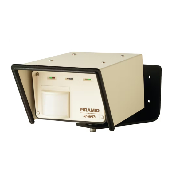
PIRAMID XL2
Passive InfraRed And Microwave Intruder Detector
Outdoor Motion Sensor
Models
SDI-76XL2 and SDI-77XL2
Protection Technologies, Inc.
529 Vista Blvd.
Sparks, Nevada 89434
800-428-9662
Phone: 775-856-7333
Fax:
775-856-7658
www.protechusa.com
info@protechusa.com
INSTALLATION GUIDE
February 1, 2009
TECH SUPPORT
800-428-9662
Advertisement
Table of Contents

Summary of Contents for protech PIRAMID XL2
- Page 1 Walk Test LED Explanation INSTALLATION GUIDE February 1, 2009 Green Is Good - Green “ECI” (Environmental Caution Indicator) LED’s ON mean each technology PIRAMID XL2 is stable and ready for walk-test. Optional XL- Passive InfraRed And Microwave Intruder Detector Sounder is silent. Plug-In Outdoor Motion Sensor MW “ECI”...
-
Page 2: Table Of Contents
Walk Test LED Explanation Model No:______________________________ Quick Installation Reference A Basic Description Serial No:_______________________________ Specifications Installation Lens Module:____________________________ Mounting PIRAMID XL2 Universal Pole Mount Best Mounting Location Circle Sensor Settings Mounting Height Wiring & Preliminary Set-Up Sensitivity Setting: Minimum Wire Size 1 2 3 4 5 6 7 8 9 10 (Min.) -
Page 3: Quick Installation Reference
For optimum performance it is best to use the sensitivity at maximum. (pg. 5) PIRAMID XL2 as a motion sensor to protect specific 7. Plug-in “wired” terminal block. Route cable under assets and strategic areas. Generally the sensor is not “cable holders”. -
Page 4: Installation
WIRING AND PRELIMINARY INSTALLATION MOUNTING PIRAMID XL2 SET-UP 1. The PIRAMID XL2 comes equipped with a wall MINIMUM WIRE SIZE: mount bracket. Install the wall mount bracket 1. With the housing/shroud assembly attached to the where the sensor will be located. Ensure that it is mounting bracket, feed the wire through the conduit firmly mounted and free from extreme vibration. -
Page 5: Stabilization Time
The Sensitivity Control Switch is very precise as the enough so that the sensor will be held in place but PIRAMID XL2 can determine the exact “distance can be aimed slightly upward and downward in in inches (cm.)” that an object must move to initiate approximately 1 degree increments. -
Page 6: Enhanced Bird/Animal Immunity Switch
Therefore, rejection is the SENSITIVITY CONTROL. the PIRAMID XL2 may not detect an intruder or a Settings of 1, 2, 3 and 4 are best. vehicle traveling at a rate of speed above 3... -
Page 7: Use As A Motion Sensor
Fast Beep = Microwave Technology Only in Alarm Continuous Tone = XL Sensor in Alarm (Both PIR and DO use the PIRAMID XL2 as a motion sensor MW Technologies in Alarm Simultaneously) with a “wide field of view” lens module. You will be able to adjust the sensor’s sensitivity setting in the... -
Page 8: Choose A Solid Mounting Base
CHOOSE A SOLID MOUNTING BASE FOR THE SENSOR DON’T mount the sensor on a surface prone to extreme vibration, such as chain link fence without support or on the flimsy siding of a metal building. DO mount on a solid wall or pillar. If mounting on a metal building, be sure to find a support structure to ensure a vibration free mounting. -
Page 16: Installation Check List
You are experiencing false alarms. PROTECH recommends a field setting of 1, 2, 3, 1. Check input voltage as described in item 1. It is best to 4, or 5 in commercial applications. A field setting check voltage with primary power disconnected from of “1”... - Page 17 Changing The Lens Module NOTES...
Need help?
Do you have a question about the PIRAMID XL2 and is the answer not in the manual?
Questions and answers