Table of Contents
Advertisement
Quick Links
Advertisement
Table of Contents

Summary of Contents for Offshore 3345 NMEA2000
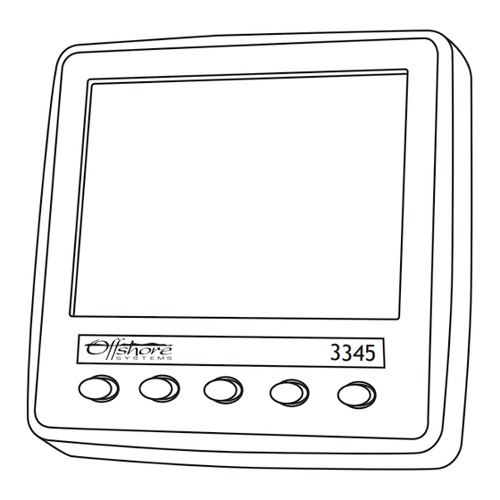
- Page 1 NMEA2000® MULTIFUNCTION DISPLAY Part Numbers: 3345 USER MANUAL Revision 1.0...
-
Page 3: Table Of Contents
Contents 1 Introduction ...........3 1.1 Firmware Revision ........3 1.2 Product Features ..........3 2 Installation .............4 2.1 Unpacking the box.........4 2.2 Mounting the unit .........4 2.3 Connecting the NMEA2000 Interface Cable ..4 3 Display Screens ..........5 3.1 Screen / Keypad Brightness Control ....5 3.2 Tank Display ..........5 3.3 Battery / DC Source Supply ......7 3.4 Generator / AC Source Supply ......8... - Page 4 4.2.2.5 Percent Only Display .......15 4.2.3 Battery Setup ..........15 4.2.3.1 Battery Name Setup .........15 4.2.3.2 Battery Config Setup ........17 4.2.3.3 Battery Alarm Setup ........17 4.2.4 External Control Setup .......18 4.2.5 AC Setup ...........19 4.2.5.1 AC Source Name Setup ......19 4.2.5.2 AC Custom Setup ........21 4.2.6 Sys &...
-
Page 5: Introduction
INTRODUCTION The Offshore System’s NMEA2000® 3345 MultiFunction Display is designed to monitor and display information about the vessel’s tanks, DC supplies such as battery banks, Wind Generators or Photovoltaic panels and AC Supplies such as generators, shore power or AC busses. -
Page 6: Installation
INSTALLATION 2.1 UNPACKING THE BOX You should find the following items in the 3345 shipping box: 1 x 3345 NMEA2000® 3345 MultiFunction Display 1 x 3345 NMEA2000® Interface Cable 1 x Bag containing 4 mounting studs and thumbwheel nuts 1 x 3345 User Manual (This document) 2.2 MOUNTING THE UNIT... -
Page 7: Display Screens
DISPLAY SCREENS When the unit powers on it displays the initial product identity screen for a few seconds and then displays the Tank Display. 3.1 SCREEN / KEYPAD BRIGHTNESS CONTROL The unit has five tactile buttons along its lower face and pressing any of the first four buttons will bring up the button bar which identifies the current button function. - Page 8 Here we can see that the Tank Display screen is split into 4 quadrants so the user can monitor 4 tanks at once. The centre of the screen at the junction of the four quadrants displays the Quadrant Page Number which in the above case is Page 0. The display has eight different pages available which are selected by repeatedly pressing the “TANK”...
-
Page 9: Battery / Dc Source Supply
Pressing the first button the top left hand quadrant will change to display each of the different tank sender levels being received and then a blank page in case the user does not wish to display any tank in a given quadrant. Then by pressing the “BACK ARROW” button that selection will be remembered and the display will revert to the normal tank display. -
Page 10: Generator / Ac Source Supply
unit is delivered each battery or DC source has a generic name that can be set to any name the user wishes to help identify the Battery or DC source. See section 4.2.4 later in this manual for information on how to do this. 2. -
Page 11: Configuration
CONFIGURATION There are a number of configurable settings on the 3345 to allow the user to configure the unit to most closely match their requirements. These are accessed by pressing and holding the right hand button for at least 5 seconds which will start the Config Menu. 4.1 CONFIG MENU On this menu use the up and down arrow keys to change the yellow highlight to the action required and then press “ENTER”... -
Page 12: Pin Entry
4.2 PIN ENTRY By moving the yellow highlight to “SETTINGS (PIN Reqd)” and pressing enter the display will show the “CONFIG PIN ENTRY” screen to allow the user to enter a security PIN to access the configuration screens. This is designed to ensure that only authorised persons can make changes in this area. -
Page 13: Settings Menu
4.2.1 SETTINGS MENU The “SETTINGS MENU” offers multiple options as shown below Note the small arrow on the left hand screen indicates that there are more options than can be shown on one page. All these options and the ones not shown are accessed by moving the yellow highlighter to the chosen option and then pressing “ENTER”... -
Page 14: Tank Name Setup
4.2.2.1 TANK NAME SETUP This screen is used to assign a 16 character name to each tank to identify the tanks more easily on the tank display pages as can be seen on the following screen. Firstly the user must select the tank type that is being named by pressing the “TANK TYPE” button. -
Page 15: Tank Volume Calibrate
4.2.2.2 TANK VOLUME CALIBRATE This screen is used to set the volume calibration table inside an Offshore System’s 3271 or 3281 Tank Level Sender. The first screen allows the user to choose the tank type and tank instance of the sender to be calibrated. -
Page 16: Fluid Units Setup
4.2.2.3 FLUID UNITS SETUP This screen is used to choose between displaying the Fluid Units in Litres, US Gallons or Imperial Gallons as can be seen by the following screen. The user can change the units by using the “UP” and “DOWN” arrows and pressing “ENTER” to select their units of choice. -
Page 17: Percent Only Display
Type Status and Alarm level for each alarm type. When the selected alarms have been set press the “ENTER” key to store them and then the “EXIT” key to return to the settings menu. 4.2.2.5 PERCENT ONLY DISPLAY ON/OFF This is a toggle menu item which will always show the fluid level numeric value in percent rather than amount. - Page 18 Firstly, by pressing the up arrow and down arrow buttons select the battery instance or battery number to be named then press “ENTER”. Next use the “UP” and “DOWN” arrow keys to change the first character of the name then press the right key to move to be able to change the next character and so on.
-
Page 19: Battery Config Setup
4.2.3.2 BATTERY CONFIG SETUP This screen allows you to select an Offshore Systems DC monitor by instance and change its properties. First select the instance using the “UP” & “DOWN” arrows on the left (if the battery instances have been given names this will also show up) then press enter to select. A new right arrow button will appear once the instance has been selected. -
Page 20: External Control Setup
4.2.4 EXTERNAL CONTROL SETUP This screen is used to set up the conditions to operate the 3478 Relay Output Module so that it can control external alarms, external pumps and other relay controlled actions. Firstly the user needs to select the Device Instance of the 3478 by using the following screen. When the Device Instance has been chosen pressing “ENTER”... -
Page 21: Ac Setup
The user can select the Tank Type, the Tank Instance, the Activation trigger and the activation level in 5% steps. When this is done, pressing “ENTER” sets up the system to issue relay controls every time a level passes the activation threshold. 4.2.5 AC SETUP 4.2.5.1 AC SOURCE NAME SETUP This screen is used to assign a 16 character name to each AC Source to identify it more easily on... - Page 22 Firstly, by pressing the up arrow and down arrow buttons select the AC Source instance to be named then press “ENTER”. Next use the Up and down arrow keys to change the first character of the name then press the right key to move to be able to change the next character and so on. Please note that the characters will cycle through A to Z upper case then a to z lower case, then a blank then numbers from 0 to 9.
-
Page 23: Ac Custom Setup
4.2.5.2 AC CUSTOM SETUP This screen allows you to select an Offshore Systems AC monitor by instance and change its properties. First select the instance using the “UP” “DOWN” arrows on the left (if the battery instances have been given names this will also show up) then press “ENTER” button to select. -
Page 24: Config Pin Setup
The user should use the “UP” and “DOWN” arrows to change the value of the Instance that is underlined and then use the “RIGHT” arrow to select the other Instance. When the Instance values are correct press “ENTER” to store them and “EXIT” to return to the Settings Menu. -
Page 25: Com Viewer
4.3 COM VIEWER By moving the yellow highlight to “ DIAGNOSTICS” and then to “COM VIEWER” and pressing “ENTER” the unit will display the communications traffic arriving to the device. This is shown below. This is an engineering diagnostic screen and not normally used. Press “EXIT” to return to the “CONFIG MENU”... -
Page 26: About
4.5 ABOUT By moving the CONFIG MENU yellow highlighted selection to “ABOUT” and by pressing enter you will see a screen similar to that below. This screen displays data about the unit including the software version and unit serial number which will identify the exact unit if requested. -
Page 27: Maintenance
MAINTENANCE ● Clean the unit with a soft cloth. ● Do not use chemical cleaners as they may remove paint or markings or may corrode the enclosure or seals. ● Ensure that the unit is mounted securely and cannot be moved relative to the mounting surface. -
Page 28: Technical Specification
As Offshore Systems are constantly improving their products specifications are subject to change without notice. Offshore System’s products are designed to be accurate and reliable however they should only be used as aids to navigation and not as a replacement for traditional navigation aids and techniques. - Page 29 Electrical and Mechanical Operating Voltage 10 to 32 Volts Power Consumption 250mA Load Equivalence Number Reverse Battery Protection Indefinitely Load Dump Protection Yes to SAE J1113 Size 95mm (W) x 95mm (H) x 23mm forward and 23mm rear (D) Weight 160gm Environmental IEC 60954 Classification...
-
Page 30: Technical Support
TECHNICAL SUPPORT If you require technical support for any Offshore Systems products you can reach us using any of the following ways: ● Tel: +44(0)1425 610022 ● Fax: +44(0)1425 614794 ● Email: support@osukl.com ● Web: www.osukl.com ● Post: Offshore Systems UK Ltd... -
Page 31: Warranty
Offshore Systems option, of any product not meeting the above limited warranty and which is returned to Offshore Systems; or if Offshore Systems is unable to deliver a replacement that is free from defects in materials or workmanship, Purchaser’s payment for such product will be refunded. -
Page 32: Troubleshooting/Faq
Web: www.osukl.com Copyright © 2013 Offshore Systems (UK) Ltd. All rights reserved.Our policy is one of continuous product improvement so product specifications are subject to change without notice. Offshore Systems products are designed to be accurate and reliable. Howeve r, they should be used only as aids to vessel monitoring, and not as a replacement for traditional navigation and vessel monitorin g techniques.
Need help?
Do you have a question about the 3345 NMEA2000 and is the answer not in the manual?
Questions and answers