
Summary of Contents for Queclink RS232
- Page 1 RS232 Camera User Guide For GVxxx-Series Devices ACCEACR100UG001 Revision: 1.00 http://www.queclink.com sales@queclink.com...
- Page 2 Furthermore, system validation of this product designed by Queclink within a larger electronic system remains the responsibility of the customer or the customer’s system integrator. All specifications supplied herein are subject to change.
-
Page 3: Table Of Contents
RS232 Camera User Guide Contents Contents ............................2 0. Revision History ........................... 3 1. General Description ........................4 2. Product Specification ........................5 2.1. Appearance .......................... 5 2.2. Parts List ..........................6 2.3. Camera Specification ......................7 3. Installation ............................. 8 3.1. -
Page 4: Revision History
RS232 Camera User Guide 0. Revision History Revision Date Author Description of change 1.00 2013-12-05 Ricker Liu Initial ACCEACR100UG001 - 3 -... -
Page 5: General Description
RS232 Camera User Guide 1. General Description RS232 Camera is a 300K pixel camera with RS232 logic level output, which could directly connect with device (with RS232 port) of Queclink. GVxxx-Series ACCEACR100UG001 - 4 -... -
Page 6: Product Specification
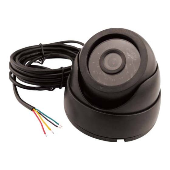
RS232 Camera User Guide 2. Product Specification 2.1. Appearance Camera Power Adapter ACCEACR100UG001 - 5 -... -
Page 7: Parts List
RS232 Camera User Guide 2.2. Parts List Name Picture Remark Camera RS232 Camera Wide input voltage is Power Adapter from 10V to 24V; (Optional) output voltage is 5V ACCEACR100UG001 - 6 -... -
Page 8: Camera Specification
RS232 Camera User Guide 2.3. Camera Specification Operating Temperature -20℃ to 70℃ Pixel 300K Resolution 160×120, 320×240, 640×480 Output Format JPEG Operating Voltage Communication Baud 115200 Rate Operating Current Below 100 mA Illumination (Min) 1 lux Colour Balance Auto Camera Lens 2.8 MM infrared R940 light... -
Page 9: Installation
RS232 Camera User Guide 3. Installation 3.1. Interface Description There is 4-wire interface on Camera, and 2-wire input interface (wide input range: 10V-24V) and 2-wire output interface (the output voltage is 5V and the output current is 1.5A) on Power Adapter. The description of the wires and sample connection between Camera, Power Adapter and GV200/GV300 are shown as follows. -
Page 10: Interface Definition
RS232 Camera User Guide 3.2. Interface Definition 1. Camera Interface Definition PIN Name Color Picture Description Power supply BLACK Ground RS232 logic level, YELLOW receive data RS232 logic level, GREEN transmit data 2. Power Adapter Interface Definition PIN Name Color... -
Page 11: Camera Interface
Connect to Camera Color Description Name GV300 GV200 5V input BLACK Ground RS232 logic level, receive data, 4-wire GREEN connect to TXD of GV300/GV200 PIN5 TXD PIN11 TXD2 Interface devices RS232 logic level, transmit data, YELLOW connect to RXD of GV300/GV200... -
Page 12: Power Adapter Interface
RS232 Camera User Guide 3.4. Power Adapter Interface Power Adapter Interface Connects to Camera POWER PIN Name Color Description Camera ADAPTER Input Power input. Input range: DC 10V-24V Interface BLACK Ground The output voltage is 5V with current VOUT_5V RED... -
Page 13: Connection Sample
RS232 Camera User Guide 3.5. Connection Sample Camera connection with GV300 device as follows: ACCEACR100UG001 - 12 -... -
Page 14: Message Format And Operation
RS232 Camera User Guide 4. Message Format and Operation Reference GVxxx @Track Air Interface Protocol. ACCEACR100UG001 - 13 -...
Need help?
Do you have a question about the RS232 and is the answer not in the manual?
Questions and answers