
Subscribe to Our Youtube Channel
Summary of Contents for Ice TRICE ‘Q’
-
Page 1: Owners Manual
Inspired Cycle Engineering Ltd T R I C E ‘Q’ & T R I C E ‘T’ STEP-BY-STEP ASSEMBLY INSTRUCTIONS OWNERS MANUAL... -
Page 2: Table Of Contents
They are well worth taking special note of. We hope you enjoy owning and riding your Trice as much as we like making these great machines. Chris, Neil and the ICE team 1.1 What’s in this manual? 1.0 Introduction..........................2 1.1 What’s in this manual?.......................2... - Page 3 4.10 Fitting Radical bags ....................... 39 4.11 Fitting the optional chainrings ....................39 4.12 Chainring guard ........................40 4.13 Bar end shifters ........................41 4.14 Rear full mudguard........................ 41 4.15 Fitting a Rohloff ........................42 5.0 Riding your TRICE........................43 5.1 Getting on and off the trike.
-
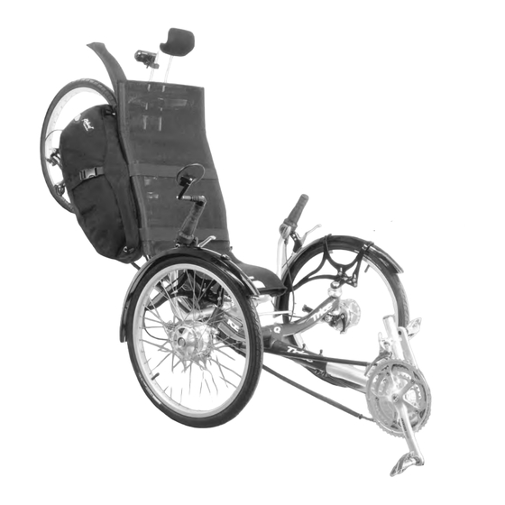
Page 4: Overview
1.1 Overview... -
Page 5: Assembling Your Trice
2.0 Assembling your TRICE Assembly tools required: 3mm Hex Key Bicycle pump 4mm Hex Key 8mm wrench 5mm Hex Key 10mm wrench 6mm Hex Key 19mm wrench 8mm Hex Key Chain link remover 10mm Hex Key Sharp knife Cable cutter Small flat screwdriver TIP –... -
Page 6: Unpacking
2.1 Unpacking Carefully unpack the contents of the box and inspect for any damage that may have occurred during shipping. You should be able to unpack your trike without resorting to a knife; if you use one, be careful not to cut through the parts or to mark the paintwork. - Page 7 Handlebars Front Wheels (drum brake version shown) Rear Wheel Rear and Front Derailleurs Chaintubes Axle bolts...
- Page 8 Seat Mount TT Bracket (standard with T only) Seat Cover and Frame (mesh seat models) Seat and Cover (hard- shell seat models)
-
Page 9: Fit And Set The Handlebars To An Approximate Position
2.2 Fit and set the handlebars to an approximate position. All versions: Slacken off the two clamps on the steerer, insert the handlebars and adjust them to an upright position. They only need to be lightly tightened at this stage. Find the cable outer casings that were packed with the derailleurs. -
Page 10: Fit Front Drum Brake Wheels
2.3a Fit front drum brake wheels Note: if you have purchased disc brakes, please refer section 2.3b Note: If you have purchased the optional quick- release kit, please refer to the instructions for its installation in Accessories Section of this manual. Located in a pack are the drum brake pins. -
Page 11: Fit Front Disc Brake Wheels
2.3b Fit front disc brake wheels Note: if you have purchased drum brakes, please refer section 2.3a Note: If you have purchased the optional quick-release kit, please refer to the instructions for its installation in Accessories Section of this manual. Identify the left-hand and right-hand wheels (there are tape labels fastened to the spokes). -
Page 12: Installing And Connecting The Front Disc Brakes
2.4b Installing and connecting the front disc brakes. Note: if you have purchased drum brakes, please refer section 2.4a The disc brake system is supplied fully assembled and bled. It is strongly recommended that you install the brakes supplied without disconnecting any hoses or attempting to shorten the hose Route the hose down to the kingpost disc mount. -
Page 13: Fitting The Parking Brake Strap
2.5 Fitting the parking brake strap There are 2 parking brake straps made of Velcro and they wrap around the brake lever and grip as seen below. They are essential if you do not want your trike going off on it’s own. You will be surprised how little a slope is necessary to get the trike moving. -
Page 14: Fitting The Rear Section To The Cruciform
2.6 Fitting the rear section to the cruciform Slide the rear section into the cruciform, taking care not to damage the plastic shim located inside the rear of the main frame. A small amount of lubricant has been applied at the factory. Evenly tighten the two frame bolts with a 5mm hex key, until the bolts just bite. - Page 15 Aligning the top of the cover with the top of the seat frame, place the back of the cover against the frame. Thread the top strap through the top buckle, and pull snug. Thread the next strap down through its corresponding buckle and pull snug.
-
Page 16: Assembling The Seat - Hard-Shell Seat
2.7b Assembling the seat – hard-shell seat The hard-shell seat is supplied with 2 seat mounting brackets, which have to be fastened to the seat. The lower bracket is the wider one, and fastens underneath through the pre-drilled holes. The upper bracket is narrower, and can be mounted in one of two positions. -
Page 17: Fit The Seat To The Lowest Position
2.8 Fit the seat to the lowest position The seat is provided with 4 plastic SP-6 clamps. Two of these clamps go around the bottom seat rail, and the other 2 go around the top rail on the hard-shell seat or the 3 rail (counting from the bottom) on the mesh seat. -
Page 18: Fit The Optional Chainrings
Accessories Section of this manual before continuing assembly. 2.11 Fit the optional chainrings If you have purchased either the 55 tooth outer chainring or the 26 tooth inner chainring, refer to the instructions for their installation in Accessories Section of this manual before continuing assembly. 2.12 Fit the chainset You now need to install the left and right sides of the chainset. -
Page 19: Install And Connect The Front Derailleur
2.17 Install and connect the front derailleur Next, the front derailleur needs to be installed. Its position is determined by the size of outer chainring. Tighten the supplied M5 bolt lightly so you can adjust the position of the derailleur. The position of the derailleur must be set so the clearance between the outer plate of the cage and outer chainring is roughly 1 -3mm, when viewed from the side. -
Page 20: Assemble The Chain Tubes
Adjust the B-tension screw so it is screwed in about 2/3 of the way. Check that the rear derailleur stop screws are approximately set as shown in section 2.22 (final adjustment will take place once the chain is installed) Fit the long length of gear outer casing into the rear derailleur and around to the cable stop on the rear right- hand side of the main frame. - Page 21 the bearing in the pulley, locating the space washers as shown in the diagram. Push the bolt through the middle of the pulley plate, and mount the chain tube assembly and pulley onto the frame. Ensure that the small tab on the frame locates in the notch on the pulley plate (just above the bolt).
-
Page 22: Check The Chain Tube Lengths
2.20 Check the chain tube lengths Check for clearance between the chain tubes and the front chainset. If the top chain tube at the front is too long, shorten by cutting the tube at the front end to the required length with a sharp knife. If the lower front tube is too long, adjust the front position of the tube by loosening the tube clamp at the pulley and sliding the lower tube rearward to the required position at the front and re-clamp the tube. - Page 23 Twist the right hand rear shifter to the “9” position so that the rear derailleur lines up with the smallest rear sprocket. Twist the left hand front shifter to the “1” position so that the front derailleur lines up with the smallest front chainring.
-
Page 24: Check The Gear Shifting
Add 2 links (with the chain on both the largest sprocket and the largest chainring). This should leave just enough slack so that the rear derailleur jockey wheels are pointing forward but so that they can still move up a fraction. Then check that there is not too much slack when using the smallest chain ring and smallest cassette sprocket. - Page 25 Set the left front shifter to the “1” position and the right rear shifter to the “9” whilst turning the pedals then check that there is no excessive slack in the gear cables. Slack must be removed by unclamping, pulling through and re-clamping the gear cables.
-
Page 26: Fit The Rear Mudguard
2.23 Fit the rear mudguard Note: If you have purchased the optional quick-release, full-wrap rear mudguard kit, please refer to the instructions for its installation in Accessories Section of this manual. The standard rear mudguard clips quickly on and off of a bracket which is part of the seat mount. Assemble the parts of the mudguard as shown in the picture below, and clip into place on the upper seat mount. -
Page 27: Fit The Mirror
2.24 Fit the mirror The mirror comes with instructions showing how it is to be assembled. The mirror is mounted in the top of one of the handlebars (right handlebar if you drive on the left, left handlebar if you drive on the right). -
Page 28: Adjusting Your Trice
3.0 Adjusting your TRICE Fine-tuning for leg length, seat angle, handle bar width / angle, brake lever reach, tyre pressure etc are all well worth taking time to set to your personal preference. TIP - Experiment but always go for a reasonable (a mile or two) test ride to decide if an adjustment is right for you. -
Page 29: Seat Angle Adjustment
The elastomers have different compression characteristics, and you may find other combinations of elastomer hardness and pin position which suit the roads you ride on and your riding style better; it is just a matter of trying different combinations. The elastomer system is simple and small enough that you can carry a couple of elastomers in your pocket and change them when you are out on a ride. - Page 30 The FB bracket is used to move the seat backwards on the trike. This is useful if the rider is has long legs, and cannot adjust the pedals far enough away from them. Fit the FB bracket to the trike with the supplied clamps, then fit the seat as you would normally (section 2.7).
-
Page 31: Leg Length
3.6 Leg length A small adjustment can be quite noticeable, just like adjusting the saddle on a conventional bike. • Change gear to the smallest chain ring. • Undo the two clamp bolts under the front boom. They must be loose. •... -
Page 32: Ice Optional Accessories
4.0 ICE Optional Accessories 4.1 Front mudguards Assembly The mudguards consist of three parts • the mudguard bracket, which fastens to the trike • the mudguard frame, which fastens to the bracket, and holds the plastic profile in place. These are left and right handed. -
Page 33: Computer
Note: If you have purchased the optional quick-release kit, please refer to the instructions for the kit in this section of this manual. The mudguards can also be adjusted to fit various tyre sections. With the mudguard fitted to the trike, slightly loosen the two bolts holding the mudguard bracket to the frame (so the two parts can just be slide against one another). -
Page 34: Handlebar" Bag Side Mount
Please ensure that the mount is tightened properly. 4.5 Extra water bottle mount An extra water bottle mount can be fitted to the seat frame by using the option ICE bottle cage mount and a bottle cage. Fitting instructions are included with the mounts. -
Page 35: Neck Rest
4.6 Neck rest Assembly The neckrest cover needs to be installed on the neckrest frame. Put your fingers up inside the cover, and peel apart the Velcro® strip near the top. Now slide the cover over the frame as shown until the top of the frame is past the Velcro®... -
Page 36: Quick-Release Kit
Adjustment The optional neck rest is fitted to the top rail of the seat frame. The neck rest is adjustable for height and angle, and is designed to suit a wide range of riders. We have found the best position for the neck rest is one where the pad sits just under the base of the skull. -
Page 37: Assembling And Fitting The Suspension Rack
2 x quick-release handlebar clamps These replace the handlebar clamps which are installed on your trike. To remove the old clamps, loosen the clamp bolts with a 5mm hex key, and then pull them from the end of the centre handlebar. - Page 38 • Bolt the brake caliper on – the brake is held on using the 2 M6 adapter fixing bolts supplied. Before installing the caliper, slacken the 2 caliper fixing bolts on the top of the caliper mount, so the caliper can slide easily over the brake rotor. •...
-
Page 39: Fitting Radical Bags
4.10 Fitting Radical bags Radical bags are extraordinarily simple to fit. The bags are simply held the right way up (so you can read the writing in the side), and they are draped over the seat. The top strap is either wrapped around the top seat tube if you don't have a neck rest fitted (photo left), or looped over the neck rest base if it is fitted (photo lower right). -
Page 40: Chainring Guard
(available inexpensively from most good bike shops or ICE). Note how the bolts fit onto the rings. Swap the large chainring for the optional 55 tooth one, and reassemble. Be certain to tighten the bolts up evenly before riding the trike. -
Page 41: Bar End Shifters
4.13 Bar end shifters Installation instructions are included with the bar end shifter kits. After you have removed the old twist shifters, remove the brake lever from the side where you would normally have a mirror, and then slip the mirror mount over the handlebar before replacing the brake lever. -
Page 42: Fitting A Rohloff
To fit the optional rear full mudguard: • Put the supplied M6 bolt through the rear-most disk brake mounting hole, and tighten the nut on from behind. This step is not necessary if you have a disc brake already installed. •... -
Page 43: Riding Your Trice
5.0 Riding your TRICE CAUTION: If your feet fall from the pedals when you are riding then they could be dragged under the cross axle of the trike. Therefore the trike should only be ridden with your feet securely attached to the pedals;... -
Page 44: Relax
This ‘No-Brake-Steer’ geometry is a safety feature that ICE developed and is designed into every trike we make. Because your weight is being supported on 3 wheels rather than 2, you will find it easier to lock up the brakes on the front wheels. -
Page 45: Hill Climbing
5.8 Hill climbing A recumbent trike or bike tends not to climb a hill as quickly as an upright bike whose rider can get off the saddle to use his/her weight to get extra effort. It will climb in comfort at a lower speed and in a lower gear. Try to keep your cadence up by shifting down early. - Page 46 Reassembly if you have the optional Q/R kit. • Stand the handlebars up and secure the quick-releases. Check that they are tight. • Fit the front wheels and secure the quick-releases. Check that they are tight. • Fit the front mudguards. •...
-
Page 47: Maintenance
6.0 Maintenance Your Trice has been built from quality materials and parts, and will last for many years with just a bit of simple maintenance. Although there is nothing on the trike that a bike shop can’t maintain for you, doing your own basic maintenance gives you a good feel of how your trike is working. -
Page 48: Disc Brakes
To bleed your brakes, follow the instructions that were supplied with your brakes. Parts and spares are available from ICE. Your brake takes mineral oil, which is not the same as hydraulic fluid used for automotive brakes and clutches. Using automotive fluid will ruin the seals in your brakes and they WILL fail! Always use mineral oil;... -
Page 49: Rear Brake
If this happens, touch-up paint is available from ICE to repair the damage. Lightly abrade the scrape with fine sandpaper, cover the exposed metal with regular metal primer, and then apply the coloured touch-up paint The front boom and rear section of your Trice are anodized. -
Page 50: Tyres, Tubes, & Wheels
6.8 Tyres, tubes, & wheels Tyres Quality tyres are vital for good traction and control while accelerating, turning and braking. Each brand of tyre has it own individual mix of puncture protection, rolling resistance, pressure rating, and durability. Finding the one that suits your riding style best is the challenge. -
Page 51: Storage
6.11 Storage If you are using the trike most days, it is best to store it somewhere dry and well ventilated. A damp, covered trike will quickly develop surface corrosion of its components, and eventually, the frame. If you are storing your bike for any considerable period (over winter or a long holiday): •... -
Page 52: Safety
7.0 Safety Between all of us here at ICE, we’ve ridden thousands of miles on trikes, and we’ve all developed good road sense. The following safety considerations are for your benefit; please give them serious consideration: • We recommend always wearing an approved cycling helmet. Get the best you can afford. If you’ve got cheap head, get a cheap helmet! •... -
Page 53: Other Important Information
8.0 Other Important Information 8.1 Recumbent/Trike forums on the Internet Now that you have your new trike, why not share your experiences with others on some of the internet forums? IHPVA Lists There is a trikes specific mailing list run by the IHPVA (International Human Powered Vehicle Association). -
Page 54: Warranty Information
If you are in any doubt about any of the advice or procedures in this manual, please contact your dealer or ICE. It is up to you to know and obey traffic laws of the country or state where you will be riding your trike. - Page 55 Tregoniggie Industrial Estate, FALMOUTH, Cornwall TR11 4SN England Telephone & FAX: 01326 378848 (+44-1326-378848 outside UK) e-mail: sales@ice.hpv.co.uk Website: www.ice.hpv.co.uk Skype: inspired_cycle_engineering_ltd Manual Revision: 14/02/2008 This manual is composed using 9pt Verdana, a British-designed font which is renowned for its excellent readability.
-
Page 56: Appendix A: Tightening Torques
Appendix A: Tightening torques Fastener Uses Hex Key (mm) Lb-ft Front derailleur clamp bolt Front derailleur cable clamp bolt Chainset - central crank bolt 35-50 25-36 Chainset - chainring bolt 5 + tool 8-10 Chainring guard bolt 4.5-6 Main frame clamp bolts 8-10 Mudguard adjusters 4.5-6... -
Page 57: Appendix B: Elastomer Limits
Appendix B: Elastomer limits Rider weight Elastomer 60-125 lbs (4-9 stone, 27-57 kg) Yellow 125-200 lbs (9-14 stone, 57-91 kg) 200-250 lbs (14-18 stone, 91-114 kg) Green 250-275 lbs (18-20 stone, 114-125 kg) Green & Yellow, or Green & Red Your elastomer will also depend on your riding style, terrain and other factors.
Need help?
Do you have a question about the TRICE ‘Q’ and is the answer not in the manual?
Questions and answers
What is the chain ring bracket size on an Ice Trice?