
Related Manuals for Shinybow USA SB-6355

Summary of Contents for Shinybow USA SB-6355
- Page 1 SB-6355 KIT HDMI HDBaseT™ 4K/UHD Tx & Rx Extender KIT up to 330 Feet (100M) (PoH, Dual LAN, 2-way IR, RS-232, SPDIF, Analog Audio, HDMI) RECEIVER TRANSMITTER...
-
Page 2: Safety Information
SAFETY INFORMATION To ensure the best results from this product, please read this manual and all other documentation before operating your equipment. Retain all documentation for future reference. Follow all instructions printed on unit chassis for proper operation. To reduce the risk of fire, do not spill water or other liquids into or on the unit, or operate the unit while standing in liquid. Make sure power outlets conform to the power requirements listed on the back of the unit. -
Page 3: Table Of Contents
TABLE OF CONTENTS HDBaseT™ with PoH 100M EXTENDER Series Thank you for purchasing the SB-6355x Kit HDBaseT™ with PoH Transmitter and Receiver. You will find this unit easy to install and highly reliable but it is essential that you read this manual thoroughly before attempting to use the converter. CONTENTS SAFETY PRECAUTIONS INTRODUCTION ..............1... -
Page 4: Features & Contents
FEATURES & CONTENTS FEATURES • HDBaseT™ HDMI / DVI extender over CATX (UTP/STP) cable • Compatible with HDMI 2.0 and HDCP 1.x, 2.2 complient • Supports 5play feature set over a single LAN cable. Transmits HDMI, Digital Audio, Bi-directional IR(CIR), 100Base-Tx Ethernet, USB 2.0, RS-232 I/O, SPDIF I/O and 13W PoH •... -
Page 5: Specifications
SPECIFICATIONS SPECIFICATIONS • Type of Extender: HDBaseT™ 5play set over a single LAN category UTP/STP Cable • Transmit Signals: HD Video/Audio, 100Base-TX Ethernet, USB (KVM), SPDIF input, SPDIF output, RS-232 i/o, IR input, IR output and PoE (48VDC) • HDMl Supports: HDMI 1.4 and HDMI 2.0 • HDCP Supports: HDCP 1.X, 2.2 compliant • Video Support: Ultra HD (4K2K@30Hz) with YCbCr 4:4:4 and 4K2K@60Hz YCbCr 4:2:0, format up to 1080p@60Hz@48b/pixel and deep color, 3D... -
Page 6: Transmitter Panels
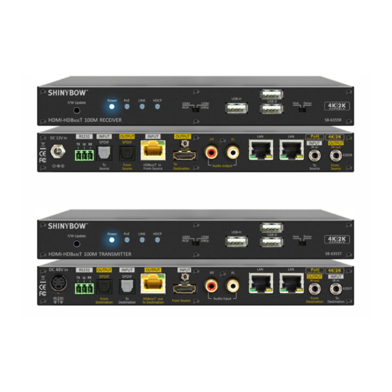
TRANSMITTER FRONT PANEL FRONT PANEL 1. POWER ON SWITCH: The power switch turns the unit on and off. The LED will illuminate blue to indicate that the switcher is ON and is receiving power. The Switcher will remember that last state during a power cycle. When power is removed and resorted, the last configuration will be evoked. - Page 7 TRANSMITTER BACK PANEL BACK PANEL 1. POWER INPUT: 6. HDMI INPUT: DC48V, 1A, (Din-4pins Male Plug). HDMI signal Input. 2. RS-232 I/O: 7/8. AUDIO INPUT: Send RS-232 via HDBaseT™ CATx cable. Extra Stereo Audio signal Input. 3. SPDIF OUTPUT: 9/10. LAN I/O: Receive the SPDIF signal from HDBaseT™...
-
Page 8: Receiver Panels
RECEIVER FRONT PANEL FRONT PANEL 1. POWER LED DISPLAY: The power switch turns the unit on and off. The LED will illuminate red to indicate that the switcher is ON and is receiving power. The switcher will remember that last state during a power cycle. When power is removed and resorted, the last configuration will be evoked. - Page 9 RECEIVER BACK PANEL BACK PANEL 1. POWER INPUT (Extra): 6. HDMI OUTPUT: DC12V, 1A, (Male Plug). Extra power offer HDMI signal Output to destination. when Transmitter PoE absent. 2. RS-232 I/O: 7. AUDIO OUTPUT: Send RS-232 via HDBaseT™ CATx cable. Extra Stereo Audio signal output.
-
Page 10: Ir Pin Configuration
IR PIN CONFIGURATION - TRANSMITTER REAR PANEL IR EXTENDER PORT - TRANSMITTER Note: When you plug the External IR extender into the switcher, the front panel IR receiver remains active. IR EXTENDER PACKAGE HOW TO SETUP THE IR EXTENDER RECEIVER COMPONENTS Note: The External IR jack has voltage on the “Ring”... - Page 11 IR PIN CONFIGURATION - RECEIVER REAR PANEL IR EXTENDER PORT - RECEIVER Note: When you plug the External IR extender into the switcher, the front panel IR receiver remains active. IR EXTENDER PACKAGE HOW TO SETUP THE IR EXTENDER RECEIVER COMPONENTS Note: The External IR jack has voltage on the “Ring”...
-
Page 12: Rs-232 Pin Configuration
RS-232 PIN CONFIGURATION - TRANSMITTER HDBASET™ EXTENDER - TRANSMITTER RS-232 PIN CONFIGURATION Note: When you plug the External IR extender into the switcher, the front panel IR receiver remains active. HDBASET™ EXTENDER - TRANSMITTER FIRMWARE UPDATE OD3.5MM JACK PIN CONFIGURATION... - Page 13 RS-232 PIN CONFIGURATION - RECEIVER HDBASET™ EXTENDER - RECEIVER RS-232 PIN CONFIGURATION Note: When you plug the External IR extender into the switcher, the front panel IR receiver remains active. HDBASET™ EXTENDER - RECEIVER FIRMWARE UPDATE OD3.5MM JACK PIN CONFIGURATION...
-
Page 14: Typical Hdbaset™ Application
TYPICAL HDBaseT™ TRANSMITTER/RECEIVER APPLICATION... -
Page 15: Rack Mounts (Optional)
19 INCH RACK MOUNT APPLICATIONS 1U RACK MOUNT (OPTIONAL) SB-6077: Complete 19 inch 1U rack mount Install Application: SB-6355T/SB-6355R 19 INCH 4U-01P RACK MOUNT Parts No.: MEER60770013000 Model No.: #1U-01p-L210MM-COV SB-6355T/SB-6355R 1U Ear mount pairs Parts No.: MEER6300ER1102 Application Diagram: #1U 19 inch - 1x Unit (HxL) (27x210mm) - Page 16 19 INCH RACK MOUNT APPLICATIONS 5U RACK MOUNT (OPTIONAL) SB-6078: Complete 19 inch 5U rack mount Install Application: SB-6355T/SB-6355R 19 INCH 5U-10P RACK MOUNT Parts No.: MEER6078001300 Model No.: #5U-10p-L210MM-COV SB-6355T/SB-6355R 5U Ear mount pairs Parts No.: MEER6078ER11000 Model No.: #5U-10p-L210MM-EAR SB-6355T/SB-6355R 5U Rack mount ear pairs Parts No.: MEER1616HA10000 Application Diagram: #5U 19 inch - 10xUnit (HxL) (27x210mm)
-
Page 17: Wall Mount Applications
19 INCH RACK MOUNT APPLICATIONS WALL MOUNT: (OPTIONAL) SB-6355T/SB-6355R: Wall mount accessories Model No.: #WM-1INCH-L210MM Install Application: SB-6355T/SB-6355R WALL MOUNT Parts No.: MEER6300ER11000 Application Diagram: #1 inch HIGH - 1x Unit (HxL) (27x210mm) -
Page 18: Limited Warranty
LIMITED WARRANTY PLEASE READ THE FOLLOWING TERMS AND CONDITIONS CAREFULLY BEFORE USING THIS HARDWARE, COMPONENTS AND SOFTWARE PROVIDED BY, THROUGH OR UNDER SHINYBOWUSA, INC (COLLECTIVELY, THE “PRODUCT”). By using installing or using the Product, you unconditionally signify your agreement to these Terms and Conditions. If you do not agree to these Terms and Conditions, do not use the Product and return the Product to SHINYBOWUSA, Inc. - Page 20 122 Rose Ln. Suite 303 | Frisco, Texas 75034 1-877-SHINY-USA 1-877-744-6987 1-972-377-2508 sales@shinybowusa.com www.shinybowusa.com...
Need help?
Do you have a question about the SB-6355 and is the answer not in the manual?
Questions and answers