Advertisement
INSTALLATION AND MAINTENANCE
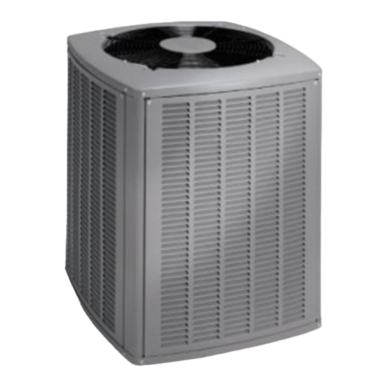
Split System Air Conditioner
The equipment covered in this manual is to be installed by trained and experienced
service and installation technicians. Improper installation, modification, service, or
use can cause electrical shock, fire, explosion, or other conditions which may cause
personal injury, death, or property damage. Use appropriate safety gear including
safety glasses and gloves when installing this equipment.
WARNING
Risk of electrical shock. Disconnect all
remote power supplies before installing or
servicing any portion of the system. Failure
to disconnect power supplies can result in
property damage, personal injury, or death.
WARNING
Installation and servicing of air conditioning
equipment can be hazardous due to internal
refrigerant pressure and live electrical com-
ponents. Only trained and qualified service
personnel should install or service this equip-
ment. Installation and service performed by
unqualified persons can result in property
damage, personal injury, or death.
WARNING
Sharp metal edges can cause injury. When
installing the unit, use care to avoid sharp
edges.
# 48387H005
INSTRUCTIONS
4SCU13LE Series
WARNING
Save these instructions for future reference
TABLE OF CONTENTS
INSTALLATION ...................................... 2
START-UP ............................................ 13
OPERATION ........................................ 17
MAINTENANCE ................................... 17
CONNECTION DIAGRAM ................... 19
Manufactured By
A.A.C.
A Lennox International Inc. Company
421 Monroe Street
Bellevue, OH 44811
*48387H005*
Page 1
Advertisement
Table of Contents

Related Manuals for Armstrong Air Conditioning 4SCU13LE Series

Summary of Contents for Armstrong Air Conditioning 4SCU13LE Series
-
Page 1: Table Of Contents
INSTALLATION AND MAINTENANCE INSTRUCTIONS 4SCU13LE Series Split System Air Conditioner WARNING The equipment covered in this manual is to be installed by trained and experienced service and installation technicians. Improper installation, modification, service, or use can cause electrical shock, fire, explosion, or other conditions which may cause personal injury, death, or property damage. -
Page 2: Installation
INSTALLATION Inspection of Shipment Upon receipt of equipment, carefully inspect it for possible General shipping damage. If damage is found, it should be noted Read this entire instruction manual, as well as the on the carrier’s freight bill. Take special care to examine instructions supplied in separate equipment, before the unit inside the carton if the carton is damaged. -
Page 3: Slab Mounting
Slab Mounting WARNING Unit must be grounded in accordance with Discharge Air national and local codes. Failure to ground unit Building Structure properly can result in personal injury or death. Refer to the furnace or blower coil Installation Instructions for additional wiring application diagrams and refer to unit rating plate for minimum circuit ampacity and maximum overcurrent protection size. - Page 4 4. Install low voltage wiring from outdoor to indoor unit and Table 2 shows the diameters for line sets up to 100' from thermostat to indoor unit (see Figure 5). although vertical lift applications and trapping require- ments need to be reviewed with Technical Services for line sets over 50'.
- Page 5 Following are some points to consider when placing and installing a high-efficiency outdoor unit: Outside Unit Placement and Installation Placement Be aware that some localities are adopting sound ordi- Install unit away nances based on how noisy the unit is at the neighbor’s from windows home, not at the original installation.
- Page 6 Refrigerant Line Sets: Transition from Vertical to Horizontal Automotive Anchored Muffler-Type Heavy Nylon Hanger Wire Tie Strap Liquid Strap Liquid Line to Vapor Line to Vapor Line Wall Wall Line Stud Stud Liquid Line Liquid Line – Vapor Line Wrapped –...
- Page 7 Flushing Existing Line Set and Indoor Coil WARNING Polyol ester (POE) oils used with R410A CAUTION refrigerant absorb moisture very quickly. It is When flushing existing line set and/or indoor very important that the refrigerant system be coil, be sure to empty all existing traps. Residual kept closed as much as possible.
- Page 8 Flushing Connections Note: The inverted R22 cylinder must contain at least the same amount of refrigerant as was recovered from the existing system. Figure 10 When the low side system pressures reach 0 psig, close 6. Set the recovery machine for liquid recovery and start the suction line valve.
- Page 9 gauges, and R22 refrigerant drum. Re-install pressure tap valve cores into the 4SCU13LE unit’s service valves. Fixed Orifice Data Install the factory-supplied fixed orifice (or thermal l l i expansion valve approved for use with R410A refrigerant) in the liquid line at the indoor coil. Refrigerant Metering Device 4SCU13LE units are designed for use with either fixed orifice or TXV systems.
- Page 10 To Access the Schrader Port: Manifold Gauge Set Manifold gauge sets used with systems charged with 1. Remove the service port cap with an adjustable wrench. R410A refrigerant must be capable of handling the higher system operating pressures. The gauges should be rated 2.
- Page 11 When using high pressure gas such as nitrogen for this purpose, be sure to use a regulator that Ball Type Service Valve can control the pressure down to 1 or 2 psig. (Valve Open) 5. Adjust nitrogen pressure to 150 psig. Open the valve on the high side of the manifold gauge set to pressur- ize the line set and the indoor coil.
- Page 12 6. When 500 microns or lower is maintained, close the manifold gauge valves, turn off the vacuum pump, and disconnect the manifold gauge center port hose from the vacuum pump. Attach the manifold gauge center port hose to a nitrogen cylinder with pressure regulator set to 150 psig and purge the hose.
-
Page 13: Start-Up
START-UP Refrigerant Charge Adjustment CAUTION If unit is equipped with a crankcase heater, it should be energized 24 hours before unit . t f start-up to prevent compressor damage as a result of slugging. * If line length is greater than 15 ft., add this amount. If line length is less than 15 ft., remove this amount. - Page 14 2. Close manifold gauge set valves. Connect the center manifold hose to an upright cylinder of R410A. R410A Temperature/Pressure Chart 3. If room temperature is below 70°F, set the room thermo- stat to call for heat. This will create the necessary load F °...
- Page 15 _____ ° Saturation Temperature °F Superheat Values for – _____ ° Liquid Line Temperature °F Fixed Orifice Systems _____ ° Subcooling Value °F (80°F DB/67°F WB Return Air) 5. Compare the subcooling value with those shown in Table 7. If subcooling is greater than shown, recover some refrigerant.
-
Page 16: Normal Operating Pressures
Normal Operating Pressures* F ° F ° F ° F ° F ° F ° F ° F ° F ° F ° F ° F ° * These are typical pressures only. Indoor matchup, L = Liquid S = Suction indoor air quality, and indoor load will cause the pressures to vary. -
Page 17: Operation
OPERATION MAINTENANCE Outdoor unit and indoor blower cycle on demand from the WARNING room thermostat. When the thermostat blower switch is moved to the ON position, the indoor blower operates Before performing maintenance operations on continuously. system, turn the electric power to unit OFF at disconnect switch(es). - Page 18 5. Check for correct voltage at unit (with unit operating). 6. Check amp-draw on blower motor. Unit nameplate _________ Actual _________ Start-Up and Performance Checklist Job Name _______________________________ Job No. ________________ Date ______________ Job Location _____________________________ City ___________________ State ______________ Installer _________________________________ City ___________________ State ______________...
-
Page 19: Connection Diagram
OUTDOOR DUAL CAPACITOR TIMED OFF CONTROL PURPLE TO 24 VAC (IF USED) BLACK POWER SOURCE 20 VA MINIMUM ORANGE NEC CLASS 2 YELLOW BLACK COMPRESSOR COMPRESSOR CONTACTOR CRANKCASE HEATER (IF USED) GROUND 208-230/60/1 GROUND BLACK K1-1 S4 HIGH 208-230/60/1 S24 LOSS YELLOW PRESSURE OF CHARGE... -
Page 20: Limited Warranty
Warrantor: Armstrong Air Conditioning Inc., 421 Monroe St., Bellevue, OH 44811 Armstrong Air Conditioning Inc. products are available under the following names: Air Ease, Armstrong Air, American Aire, Concord Subject to the limitations stated in this warranty, we warrant to the first buyer for use the residential heating, cooling or heat pump unit, when installed, operated and maintained as required by this warranty, to be free of defects in workmanship or material for a period of 5 years in residential installations (1 year in non-residential installations) from the time of installation.
Need help?
Do you have a question about the 4SCU13LE Series and is the answer not in the manual?
Questions and answers