Table of Contents
Advertisement
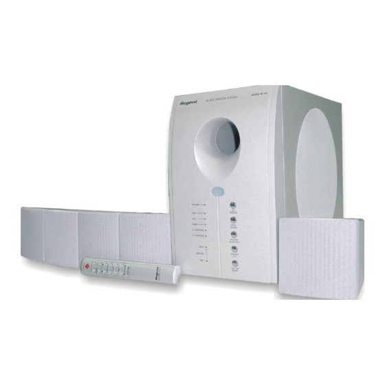
MODEL HT-391
Home Theater System
Turns Your DVD Player Into a 5.1 Channel
Home Theater Surround Sound System
The Perfect Sound System for Your DVD Player
•
Just add your TV & DVD player; everything else is in the box.
•
Incredible surround sound, perfect for DVD viewing & enhanced TV game experience.
•
Also provides superior sound for computer system
PLEASE READ CAREFULLY BEFORE USE
IB-HT391-WM-E-073003
Advertisement
Table of Contents

Related Manuals for Regent HT-391


Summary of Contents for Regent HT-391
-
Page 1: Home Theater System
MODEL HT-391 Home Theater System Turns Your DVD Player Into a 5.1 Channel Home Theater Surround Sound System The Perfect Sound System for Your DVD Player • Just add your TV & DVD player; everything else is in the box. -
Page 2: Safety Instructions
• Do not place the Home Theater system on an inclined or unstable place. • Do not place anything within 1 inch of the sides or 2 inches from the back of the cabinet. -
Page 3: Components View
Later on, you may want to change some of the optional settings like speaker volume and balance settings. Instructions for changing them, are found later in this manual. Basic Features & Benefits of this 5.1 Channel Home Theater System: 1. 5.1 channel audio decoder for home theater surround sound. -
Page 4: Table Of Contents
Introduction----------------------------------------------------------------------------------------------------------------------------------------------- 2 Location of Controls----------------------------------------------------------------------------------------------------------------------------------- 4,5 Remote Control Operation---------------------------------------------------------------------------------------------------------------------------6 • Connections Choose Your Connection-----------------------------------------------------------------------------------------------------------------------------7 Cables Needed to Connect Components to Your Home Theater System -------------------------------------------------------- 7 Speaker system connections: Speaker system connections---------------------------------------------------------------------------------------------------------------------- 8,9 Speaker Positioning Information------------------------------------------------------------------------------------------------------------------ 10,11 TV Connections ---------------------------------------------------------------------------------------------------------------------------------------- 12... -
Page 5: Location Of Controls
LOCATION OF CONTROLS FRONT OF MAIN SET (SUBWOOFER) BACK OF MAIN SET (SUBWOOFER) 1. ON / STANDBY button - Press to switch the set to on or to standby mode. 2. INPUT SOURCE button - Press several times to select the sound input source you want: DVD, AUX or GAME. -
Page 6: Location Of Controls
LOCATION OF CONTROLS REMOTE CONTROL 1. IR DIODE - Sends the signal to the set. Do not block or cover this. 2. ON/STANDBY button - Switches the player from STANDBY to ON or ON to STANDBY (if the main POWER of the set is ON). 3. -
Page 7: Remote Control Operation
Point the REMOTE CONTROL at the Home Theater’s Front Mak e su re there is a clear path between the RE MO TE CONTROL and the HOME THEATER SYSTEM so that the signal is not blocked. Tips on REMOTE CONTROL operation as indicated. -
Page 8: Connections
CONNECTIONS Choose Your Connection There are several ways to connect your Home Theater System. Please use the following chart to determine which connection is the best for you. Turn to the appropriate page and connect your Home Theater System. COMPONENTS... -
Page 9: Speaker System Connections
Before making connections, make sure the power is off. NOTE: If you would also like to improve your TV’s sound output with this Home Theater system, your TV set needs to have AUDIO output jacks. If you have a cable box or satellite receiver, you can connect the receiver’s AUDIO output directly to the AUX input or any available set of input jacks on the back of this Home Theater system. - Page 10 SPEAKER SYSTEM CONNECTIONS Tips for connecting the speaker wires Unwind and stretch out the speaker wires attached with each speakers, then push and hold down the speaker terminal tab on the back of the main set to insert each wire. Make sure the wire is fully inserted, but the insulation is not covering the inserted part of the speaker wires.
-
Page 11: Speaker Positioning Information
SPEAKER POSITIONING INFORMATION Seat Your Usual POSITION ALL 5 SPEAKERS APPROXIMATELY AT THE SAME DISTANCE FROM YOUR LISTENING POSITION. POSITION THE SUBWOOFER AS BELOW. POSITION THE SPEAKERS LIKE THIS FOR OPTIMAL LISTENING EXPERIENCE • The 4 satellite speakers and the center speaker should be placed approximately the same distance from your listening position. - Page 12 SPEAKER POSITIONING INFORMATION The left front, right front, and center speakers should be SATELLITE SPEAKERS placed at roughly the same height. The center speaker reproduces most of the dialog spoken by the actors on the TV screen, therefore it should be placed either directly above or below the center of the TV set.
-
Page 13: Tv Connections
2. Insert the stereo audio cables (included) into the AUX AUDIO INPUT L (left=white) and R (right=red) jacks or any available set of input jacks on the back of your HOME THEATER SYSTEM, and into the corresponding AUDIO OUT jacks on your TV, this will allow your TV’s sound to play through your HOME THEATER SYSTEM. -
Page 14: Tv + Dvd Connections
NOTE: You may insert the video cable directly into the VIDEO OUT jack on the back of your DVD and into the VIDEO IN jack on the back of your HOME THEATER SYSTEM. Then insert the video cable into the VIDEO IN jack on your TV, and into the VIDEO OUT jack on the back of your HOME THEATER SYSTEM. -
Page 15: Tv + Vcr Connections
Insert the stereo audio cables (included) into the AUX INPUT L (left=white) and R (right=red) jacks or any available set of input jacks on the back of your HOME THEATER SYSTEM, and into the corresponding AUDIO OUT jacks on your VCR, this will allow your VCR’s sound to play through your HOME THEATER SYSTEM. -
Page 16: Tv + Vcr + Satellite Receiver Connections
Follow the same on P14 to connect your VCR with your HOME THEATER SYSTEM. To hear the sound of the satellite programs through your HOME THEATER SYSTEM, just insert a set of audio cables (optional, not included) into one pair of the 3 audio input jacks of your HOME THEATER SYSTEM, and into the corresponding AUDIO OUT jacks of your SATELLITE RECEIVER/CABLE BOX. -
Page 17: Tv + Tv Game Connections
HOME THEATER SYSTEM, and into the VIDEO OUT jack on your TV GAME. 3. Insert another video cable into the VIDEO OUT jack on the back of your HOME THEATER SYSTEM, and into the VIDEO IN jack on your TV. -
Page 18: Tv + Video Camera Connections
HOME THEATER SYSTEM, and into the VIDEO OUT jack on your VIDEO CAMERA. (NOTE: Your video camera may have a 3.5mm triple jack, consult your camera’s booklet for details.) 3. Insert the video cable (included) into the VIDEO OUT jack on the back of your HOME THEATER SYSTEM, and into the VIDEO IN jack on your TV. -
Page 19: Aux In Connections
AUX INPUT jacks of your HOME THEATER SYSTEM (AUX stands for Auxiliary). • You can hear the sound of any one of these devices through your HOME THEATER SYSTEM if you connect the proper cables. 1. Insert the audio cables into the AUDIO OUTPUT L (left=white) and R (right=red) jacks of your TAPE RECORDER PLAYER, and into the corresponding AUX INPUT jacks or any available set of input jacks on your HOME THEATER. -
Page 20: Am/Fm Tuner Connections
AM / FM TUNER CONNECTIONS CONNECT ALL SPEAKERS AS SHOWN ON PAGE 8 (OR THE QUICK SETUP DIAGRAM SHEET). 1. Insert the audio cables into the AUDIO OUTPUT L (left=white) and R (right=red) jacks on the back of your AM/FM TUNER, and into the corresponding AUX INPUT jacks or any available set of input jacks on the back of your HOME THEATER. -
Page 21: Computer Sound Connections
COMPUTER SOUND CONNECTIONS CONNECT ALL SPEAKERS AS SHOWN ON PAGE 8 (OR THE QUICK SETUP DIAGRAM SHEET). 1. Insert the green 3.5mm audio plug of the AUDIO cable (included) into the PC AUDIO OUT jack of your PC, and insert the AUX INPUT L (left = white) and R (right = red) plugs into the corresponding AUX INPUT jacks on the back of your HOME THEATER. -
Page 22: Amplifier In Main Unit
AMPLIFIER IN MAIN UNIT REMOTE CONTROL General Make sure the POWER switch on the back of the main unit is at “ON” position. Next press the ON/STANDBY button on the front of the main set or on the REMOTE to turn the set on (or off). NOTE: The STANDBY indicator has 2 modes: flashing and steadily ON (slow flashing indicates the set is in standby, steadily on indicates the set is on). -
Page 23: Volume Adjustment
AMPLIFIER RESET BUTTON Pressing this button on the remote control will reset all 5 satellite speakers and the subwoofer to their default factory settings, normal level. NOTE: Every time you turn the set on, the MASTER VOLUME will go ba ck to the factory’s d efau lt setting;... -
Page 24: Listening Mode
LISTENING MODE NOTE: About fuse replacement. In the unusual event that nothing lights up and no sound, your fuse may have blown. To check for a blown fuse, follow the steps below. Open the fuse cover (on the back of the main set) by using a Philips screwdriver to unscrew the fuse cover cap. -
Page 25: Trouble Shooting
2. If the batteries are weak or dead, replace them with new ones (size “AAA”). 3. Point the remote control unit at a distance of less than 20 feet from the main unit of the HOME THEATER system. 4. Remove any obstacles between the remote control unit and remote control sensor. -
Page 26: Ib-Ht391-Wm-E
/ 98 X 97 X 107 mm inches / 98 X 97 X 107 mm inches / 98 X 97 X 107 mm LENOXX ELECTRONICS CORP. 2 GERMAK DRIVE CARTERET, N.J. 07008 © 2003 LENOXX ELECTRONICS CORP. MADE & PRINTED IN CHINA IB-HT391-WM-E-073003...
Need help?
Do you have a question about the HT-391 and is the answer not in the manual?
Questions and answers
What is the size of the subwoofer?
Boa tarde Estou precisando do controle, pois o meu parou, consigo adquirir?
Is the front panel still available