
Summary of Contents for emcotherme KXs
- Page 1 Operating Instructions · Part 2.1.4 emcotherm control technology emcobad emcobau emcoklima...
-
Page 2: Table Of Contents
Programmable room thermostat emcotime II ..........32 emcotherm – Electrical Connection Diagrams ....Circuitry KXs, KMS, K91-K94, K1-K4, KIQ1-KIQ3 with room thermostat or emcotime II ............... 47 Circuitry KQs and KQ1 - KQ3 with room thermostat and electronic potentiometer .........48 Circuitry KQs and KQ1 - KQ3 with room thermostat and fixed speed module.............49... - Page 3 4.10 Circuitry KQK (4- pipe) with emcotronic II ............56 4.11 Circuitry connection KQK (4- pipe) to the building automation control (DDC) ..............57 4.12 Circuitry KQKL (2- pipe) with room thermostat and electronic potentiometer .......... 58 4.13 Circuitry KQKL (2- pipe) with room thermostat and fixed speed module.............59 4.14 Circuitry KQKL (2- pipe) with...
-
Page 4: Important Information And User Instructions
emcotherm control technology Important Information and User Instructions General introduction emcotherm control technology offers products that are individually harmonised to the needs of the convector market. This technology has been developed in an environmentally-friendly and effective way according to the latest state of technology. Centralised and decentralised controlled and set switching functions allow emcotherm control technology to be matched perfectly to the product interfaces of leading manufacturers of convectors. -
Page 5: Diagrams And Descriptions In This Manual
emcotherm control technology Diagrams and descriptions in this manual → Chapter and section titles, important information and functions are displayed in bold print. → Danger, warning and information notices are structured as follows: SIGNAL WORD Description of the danger or information. Particularly important texts and keywords are displayed in bold type. -
Page 6: Supporting Documents
emcotherm control technology WARNING ! Please note that a symbol or pictogramme can never take the place of a text or instruction! Always be sure to read each text or instruction in WARNING ! full! 1.4.1 Other symbols used in this manual: Heating Cooling Secondary air... -
Page 7: Improper Use
emcotherm control technology Furthermore, it is imperative to adhere to all general safety-related conditions at the installation site as well as all relevant valid directives for the application, such as rules for accident prevention et al. Regulations and possible uses of the various emcotherm control components are documented in this manual as well as in the manual of the respective convector. -
Page 8: Warranty, Guarantee And Liability
emcotherm control technology Warranty, guarantee and liability The extent and duration of the guarantee are based on the respective contract as well as the general Terms and Conditions of emco Bau- und Klimatechnik GmbH & Co. KG. Guarantee and liability claims are generally ruled out if damage can be proven to be the result of incorrect installation, improper use or force majeure. -
Page 9: Safety Information
emcotherm control technology Safety Information Safety-conscious operation The highest level of safety and a high standard of quality are a matter of course to us, which is why all emcotherm control components have been developed, manufactured and tested according to the latest applicable norms, standards and directives. -
Page 10: User Due Diligence
emcotherm control technology User due diligence The operator of the system is obligated to ensure that → emcotherm control components are used only as intended and are in impeccable and working condition. → Only trained specialists carry out fitting, electrical installations, settings and/or changes to the default values, error / fault clearance and/or repairs. -
Page 11: Individual Room Temperature Control
emcotherm control technology Components for Individual Room Temperature Control General instructions about the installation site for emcotherm individual room temperature control components → Install the room thermostat together with the speed controller preferably on an inside wall and across from the heating source in the room. -
Page 12: Recommended Use For Emcotherm Control Technology
Alternative emcotherm Control with programmable Control with for free convection room thermostat room thermostat RT type KXs, KMs, K 1-K 4, K 91-K 94 emcotime II Control with programmable room thermostat emcotime II and speed controller DZR Control with room thermostat RT and fixed speed module FDM... - Page 13 emcotherm control technology Device Name Recommendation Alternative emcotherm Control via Control with for free and forced convection building automation control elektronic climate controller (external actuation via types KQK 4, KQKL emcotronic II (4-pipe heat exchanger) 0-10 Volt signal emcotherm Control with programmable for free and forced convection Control with room thermostat...
-
Page 14: Room Thermostat Type Emco Rt
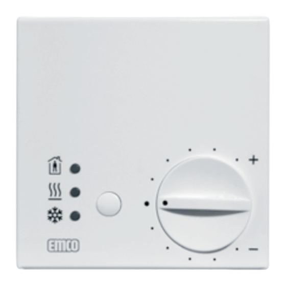
emcotherm control technology Room thermostat emco RT The room temperature controller emco RT (250 V) with change-over contact is suitable for heating and cooling in connection with all emcotherm concector systems. The controller works with thermal return and a switch temperature difference of 0.5°K. - Page 15 emcotherm control technology 3.3.3 Installing emco RT Installation should be made in a standard flush socket; combination with a dual frame is possible. ATTENTION ! If emco RT is installed together with speed controller emco DZR in a dual frame, emco RT should be installed below the speed controller. ATTENTION ! Speed controller emco DZR (install at...
-
Page 16: Speed Controller Type Emco Dzr
emcotherm control technology Speed controller emco DZR The electronic potentiometer emco DZR is for continuous speed control of emcotherm convectors with an output signal of 0-10 V. DZR is used in combination with emco RT or emcotime II. With a closed contact in the emco RT/emcotime II, use DZR to regulate the fan speed/thermal output of emco convectors. - Page 17 emcotherm control technology 3.4.3 Installation Installation should be made in a standard flush socket; combination with a dual frame is possible. ATTENTION ! If emco DZR is installed together with room thermostats emco RT or emcotime II in a dual frame, emco DZR should always be installed above the room thermostat (see fig.
-
Page 18: Electronic Climate Controller Emcotronic Ii
emcotherm control technology Electronic climate controller emcotronic II Electronic room thermostat for fixed set-point control (constant PI- control) for use in emcotherm convectors with 2-pipe and 4-pipe technology (for heating and cooling). 3.5.1 Functional components emcotronic II Displays for operation mode and operating status: 1. - Page 19 emcotherm control technology 3.5.2 Short description emcotronic II The room thermostat displays the current operation mode: → Heating mode: red LED illuminated → Cooling mode: yellow LED illuminated → When the red and yellow LED are not illuminated, set-point and actual temperature correspond.
- Page 20 emcotherm control technology 3.5.3 Setting the set-point temperature with emcotronic II The desired room temperature (set point temperature) can be set using the adjusting knob. The maximum and minimum adjustable set point temperatures (possible setting range) can be limited mechanically through the use of a limiting pin.
- Page 21 emcotherm control technology 3.5.4 Short programming description ATTENTION ! The controller has been pre-set. The pre-set values are documented in the accompanying installation instructions no. 870-1119. If the pre-set values should be changed, please follow the installation ATTENTION ! and programming description “Service Values“ (see section 10.6.5 ) or the installation instructions no.
- Page 22 emcotherm control technology 4. Xp (slew rate) has been pre-set to 2 K. With a deviation of >= 2 K between the set-point and actual value, the controller provides an output voltage of 10 Volt, which in turn means 100 % fan speed. If this slew rate is changed (reduced), the value can be increased, for example to 6 K.
- Page 23 emcotherm control technology Additional adjustment / programming options: Xtn = dead zone, The temperature difference between heating and cooling in which the controller emits neither a heating nor cooling signal is called the dead zone. This unit is especially important in the transitional period in which there is can be no heating or cooling.
- Page 24 emcotherm control technology 3.5.5 Service-Values Subject to technical changes without prior notice! June 2008...
- Page 25 emcotherm control technology 3.5.6 General technical data Description emcotronic II Feeding voltage 24 V ~/= 50 ... 60 Hz; ± 20 % Power input approx. 2.5 VA Switching current / Output voltage NTC internal (remote sensor optional) Temperature sensor F 500 H 250 Control mode PI-control, constant Control parameter...
- Page 26 emcotherm control technology (Standard) 3.5.7 Wall installation emcotronic II Standard delivery of the electronic climate controller emcotronic II is in a casing for wall mounting (see scale drawing top left). Proceed as follows for wall installation: Set a ca. 5 mm wide screwdriver (1) in the notch on the housing and turn to carefully loosen the casing cover until it can be removed (2)
- Page 27 emcotherm control technology ATTENTION ! When fitting the emcotronic II to the wall, there must be a minimum spacing of 5 mm from other wall-mounted casings, as it may otherwise be difficult to properly open or attach the casing cover. ATTENTION ! 3.
- Page 28 emcotherm control technology (optional) 3.5.8 emcotronic II in flush installation Using an optional cover-sandwich plate (accessory – not part of standard delivery package), the climate controller emcotronic II can be installed on a standard flush socket. ATTENTION ! Before installation, the cable inlets in the flush socket must be sealed (see fig.
- Page 29 emcotherm control technology 3. Insert PCB and make the electrical connection to the PCB terminal block as illustrated in the wiring diagram and connection plan (see chapter “connection diagrams“). 4. Attach the casing cover and snap the adjusting knob into place (see section “wall installation“, steps 4 and 5) 3.5.9 Mounting the emcotronic II using a mounting bracket (optional)
- Page 30 emcotherm control technology 3.5.10 Optional accessories for emcotronic II Item-No. Descriptiion EGH 101 Dew point control switch 296724 000 Sensor holder for wall installation 368139 000 Rubber stopper as sensor holder in duct 303124 000 Flush socket (only in connection with 313347 001) Mounting set for sensor 313214 001 (holder, bronze spring, tension strap, heat-conductive paste)
- Page 31 emcotherm control technology 3.5.11 Electrical connection Connect the electronic potentiometer according to the schematic diagram (also see chapter 4 “Electrical Connections“ in this manual). Wire size: Up to 1 mm No grounding wire necessary because the device has protective insulation Schematic diagram: 4-pipe system 2-pipe system...
-
Page 32: Programmable Room Thermostat Emcotime Ii
emcotherm control technology Programmable room thermostat emcotime II Programmable room thermostat controller (250 V) as a digital clock thermostat for flush installation with 2-way contact for heating and cooling. When used in combination with the speed controller emco DZR, emco- time II is suitable for use in all emcotherm convector systems 3.6.1 Function elements emcotime II... - Page 33 emcotherm control technology (for the standard automatic programmes Mon ... Thu) 3.6.2 Temperature-timing chart Illustration of daily temperature – time distribution at 2, 4, 6, cycle times per day Self-learning heating curve The device recognises automati- cally when heating must begin so that the desired room tempera- ture is achieved at the set time.
- Page 34 emcotherm control technology 3.6.3 Pre-set programmes Programme Cycle times Main application 21°C 18°C 15°C Room heating 21°C 18°C 15°C Underfloor heating with limit 28°C 18°C 18°C Underfloor heating 21°C 18°C 18°C Room heating 21°C 18°C 18°C Room heating ATTENTION ! If a programme is selected, the previously set “number of cycles”...
- Page 35 emcotherm control technology 3.6.6 Selecting mode of operation (function) Use the -button to address the (functions). modes of operation Make the desired selection by pressing the Mode button until the selec- tion indicator points to the desired mode of operation. The following modes of operation are available: Symbol Mode Function...
- Page 36 emcotherm control technology 3.6.7 Manual operation a) Changing the temperature for a limited time: 1. Press the key or key until the desired temperature is displayed. (If the temperature should only be checked, end by pressing key.) 2. Confirm by pressing the key or otherwise the set temperature will be automatically accepted after 5 seconds and the actual temperature will be displayed again.
- Page 37 emcotherm control technology b) Changing the temperature permanently by programming manual operation The set temperature remains in place permanently. Terminate by selecting another mode of operation Press the key until the arrow is pointing to 2. Use the key or key to set the desired temperature.
- Page 38 emcotherm control technology 3.6.8 Coming/Going function key can be used as a coming/going key, meaning that when occupants leave the room, the temperature can be lowered at the push of a button. Pressing the button again will revert the system back to the programme.
- Page 39 emcotherm control technology 3.6.9 Week programme This programme repeats the programmed cycle times week for week. 1. Press the key until the arrow is pointing to The current actual temperature and time of day will be displayed. The arrows indicate the weekday (1..7), the current daytime range and the set-point temperature...
- Page 40 emcotherm control technology 3.6.11 Party mode This function suspends the automatic programme for 3 hours. Áfter this time is up, the system always reverts back to the week programme. Activating party mode Press the key until the arrow is pointing to The evening temperature will now be activated for 3 hoursl.
- Page 41 emcotherm control technology ATTENTION ! If there is a voltage failure, the daily counter will be switched off. As soon as voltage is restored, the counter willl resume operation at the point where it was interrupted. In the event of voltage failure of > 4 h ATTENTION ! the time and date will need to be re-set (power reserve 4 h).
- Page 42 emcotherm control technology 3.6.14 Setting time/weekday Set the time and weekday here. Press until the arrow is pointing at 2. Select the current weekday 1 ... 7 with 3. Press , one hour digit will blink. 4. Set the hour with 5.
- Page 43 emcotherm control technology 8. Set one of the three temperatures using the 9. Confirm with The arrow will blink at 10. To programme further cycle times, repeat steps 4 to 9. 11. If the arrow blinks in , at the last symbol, use the key to switch to the setting mode for the next day.
- Page 44 emcotherm control technology Setting cycle times for additional day programme: The day programme will be repeated day for day Press , as described in section 10.7.15, step 3. 2. Then carry out all other steps EXCEPT step 11. The settings for the week programme will not be affected. Checking cycle times: To check which cycle times are set, do the following: Select the desired weekday or the extra day programme...
- Page 45 emcotherm control technology Checking the temperature: To check which temperature has been set, do the following: Execute steps 1 and 2 as described above. 2. Press to exit. 3.6.17 Short description for emcotime II Changing the programme Set time Execute steps 1 / 2 Select/Set Confirm Function:...
- Page 46 emcotherm control technology 3.6.18 Reset The reset button should be used when inexplicable or undefined malfunctions occur. All data except the weekday and the time will be maintained. Activating Reset: Insert a sharp object into the hole between keys 2. Now re-enter the time and date. 3.6.19 Locking to prevent unauthorised use This function prevents unauthorised manipulation on the controller.
-
Page 47: Emcotherm - Electrical Connection Diagrams
– Electrical Connection Diagrams Circuitry KXs, KMS, K91-K94, K1-K4, KIQ1-KIQ3 with room thermostat or emcotime II emcotherm room thermostat* min 2 x 0,75 mm 230 V < 3 x 1,5 mm power input 2.5 W I = 11 mA... -
Page 48: Circuitry Kqs And Kq1 - Kq3 With Room Thermostat And Electronic Potentiometer
emcotherm control technology Circuitry KQs und KQ1 - KQ3 with room thermostat and electronic potentiometer emcotherm junction box electronic 10 V IY (St) Y 2 x 2 x 0,8 potentiometer Elektron. Potentiometer 10 V 24 V~ min 2 x 0,75 mm room thermostat* Mains power input 2.5 W... -
Page 49: Circuitry Kqs And Kq1 - Kq3 With Room Thermostat And Fixed Speed Module
emcotherm control technology Circuitry KQs und KQ1 - KQ3 with room thermostat and fixed speed module emcotherm junction box 10 V 10 V 24 V~ min 2 x 0,75 mm room thermostat* Raumthermostat* Mains power input 2.5 W 230 V I = 11 mA <... -
Page 50: Circuitry Kqs And Kq1 - Kq3 With Emcotronic Ii
emcotherm control technology Circuitry KQs and KQ1 - KQ3 with emcotronic II emcotherm junction box 10 V 10 V emcotronic II IY (St) Y 2 x 2 x 0,8 Emco Tronic II 24 V~ min 2 x 0,75 mm Mains power input 2.5 W 230 V I = 11 mA... -
Page 51: Circuitry Kqs And Kq1 - Kq3 To The Building Automation Control (Ddc)
emcotherm control technology Circuitry KQs and KQ1 - KQ3 to building automation control (DDC) emcotherm junction box 0 - 10 V actuating 10 V IY (St) Y 2 x 2 x 0,8 signal from build- ing automation 2-10 V Stellsignal von DDC control DDC 10 V Sign. -
Page 52: Circuitry Kqk (2-Pipe) With Room Thermostat And Electronic Potentiometer
emcotherm control technology Circuitry KQK (2-pipe) with room thermostat and electronic potentiometer emcotherm junction box electronic 10 V IY (St) Y 2 x 2 x 0,8 potentiometer Elektron. Potentiometer 10 V 24 V~ min 2 x 0,75 mm Raumthermostat* room thermostat* Mains power input 2.5 W 230 V... -
Page 53: Circuitry Kqk (2-Pipe) With Room Thermostat And Fixed Speed Module
emcotherm control technology Circuitry KQK (2-pipe) with room thermostat and fixed speed module emcotherm junction box 10 V 10 V 24 V~ min 2 x 0,75 mm Raumthermostat* room thermostat* Mains power input 2,5 W 230 V I = 11 mA <... -
Page 54: Circuitry Kqk (2- Pipe) With Emcotronic Ii
emcotherm control technology Circuitry KQK (2-pipe) with emcotronic II emcotherm junction box 10 V 10 V emcotronic II IY (St) Y 2 x 2 x 0,8 Emco Tronic II 24 V~ min 2 x 0,75 mm Mains power input 2.5 W 230 V I = 11 mA 3 x 1,5 mm... -
Page 55: Circuitry Connection Kqk (2- Pipe) To The Building Automation Control (Ddc)
emcotherm control technology Circuitry connection KQK (2-pipe) to building automation control (DDC) emcotherm junction box 10 V 0 - 10 V actuating signal IY (St) Y 2 x 2 x 0,8 from building automation control DDC 10 V Sign. 24 V~ min 2 x 0,75 mm Mains power input 2.5 W... -
Page 56: Circuitry Kqk (4- Pipe) With Emcotronic Ii
emcotherm control technology 4.10 Circuitry KQK (4-pipe) with emcotronic II emcotherm junction box min 2 x 0,75 mm 10 V IY (St) Y 2 x 2 x 0,8 emcotronic II emcotronic II power input 2.5 W 24 V~ I = 11 mA min 2 x 0,75 mm Mains power input 2.5 W... -
Page 57: Circuitry Connection Kqk (4- Pipe) To The Building Automation Control (Ddc)
emcotherm control technology 4.11 Circuitry connection KQK (4-pipe) to building automation control (DDC) emcotherm junction box 0 - 10 V actuating signal from building auto- mation control DDC power input 2.5 W I = 11 mA Mains power input 2.5 W I = 11 mA power input 22 W I Pr = 174 mA... -
Page 58: Circuitry Kqkl (2-Pipe) With Room Thermostat And Electronic Potentiometer
emcotherm control technology 4.12 Circuitry KQKL (2-pipe) with room thermostat and electronic potentiometer emcotherm junction box electronic potentiometer Valve actuator power input 2.5 W I = 11 mA room thermostat* Mains junction box < Note: ■ In this version the set-point power input max. -
Page 59: Circuitry Kqkl (2-Pipe) With Room Thermostat And Fixed Speed Module
emcotherm control technology 4.13 Circuitry KQKL (2-pipe) with room thermostat and fixed speed module emcotherm connection box 10 V 10 V 24 V~ Valve actuator power input 2.5 W I = 11 mA min 2 x 0,75mm room thermostat* Raumthermostat* Mains junction box 230 V... -
Page 60: Circuitry Kqkl (2- Pipe) With Emcotronic Ii
emcotherm control technology 4.14 Circuitry KQKL (2-pipe) with emcotronic II emcotherm junction box 10 V 10 V IY (St) Y 2 x 2 x 0,8 emcotronic II emcotronic II 24 V~ Valve actuator power input 2.5 W I = 11 mA min 2 x 0,75 mm Mains 230 V... -
Page 61: Circuitry Connection Kqkl (2-Pipe) To Building Automation Control (Ddc)
emcotherm control technology 4.15 Circuitry connection KQKL (2-pipe) to building automation control (DDC) emcotherm junction box 0 - 10 V actuating 10 V signal from building IY (St) Y 2 x 2 x 0,8 automation control 2-10 V Stellsignal von DDC 10 V Sign. -
Page 62: Circuitry Kqkl (4- Pipe) With Emcotronic Ii
emcotherm control technology 4.16 Circuitry KQKL (4-pipe) with emcotronic II emcotherm junction box Valve actuator power input 2.5 W I = 11 mA min 2 x 0,75 mm 10 V emcotronic II IY (St) Y 2 x 2 x 0,8 emcotronic II 24 V~ Valve actuator... -
Page 63: Circuitry Connection Kqkl (4-Pipe) To Building Automation Control (Ddc)
emcotherm control technology 4.17 Circuitry connection KQKL (4-pipe) to building automation control (DDC) emcotherm junction box 0 - 10 V actuating signal from building Valve actuator automation control power input 2.5 W IY (St) Y 2 x 2 x 0,8 10 V I = 11 mA min 2 x 0,75 mm... -
Page 64: Circuitry Bkq (2-Pipe) With Room Thermostat And Electronic Potentiometer
emcotherm control technology 4.18 Circuitry BKQ (2-pipe) with room thermostat and electronic potentiometer emcotherm junction box electronic 10 V IY (St) Y 2 x 2 x 0,8 potentiometer Elektron. Potentiometer 10 V 24 V~ min 2 x 0,75 mm Raumthermostat* room thermostat* Mains power input 2.5 W... -
Page 65: Circuitry Bkq (2-Pipe) With Room Thermostat And Fixed Speed Module
emcotherm control technology 4.19 Circuitry BKQ (2-pipe) with room thermostat and fixed speed module emcotherm connection box 10 V 10 V 24 V~ min 2 x 0,75 mm Raumthermostat* room thermostat* Mains power input 2,5 W 230 V I = 11 mA <... -
Page 66: Circuitry Bkq (2- Pipe) With Emcotronic Ii
emcotherm control technology 4.20 Circuitry BKQ (2-pipe) with emcotronic II emcotherm junction box 10 V 10 V emcotronic II IY (St) Y 2 x 2 x 0,8 Emco Tronic II 24 V~ min 2 x 0,75 mm Mains power input 2.5 W 230 V I = 11 mA 3 x 1,5 mm... -
Page 67: Circuitry Bkq (2-Pipe) To Building Automation Control (Ddc)
emcotherm control technology 4.21 Circuitry BKQ (2-pipe) to building automation control (DDC) emcotherm junction box 10 V 0-10V actuating IY (St) Y 2 x 2 x 0,8 signal from building automation control 10 V Sign. 24 V~ min 2 x 0,75 mm Mains power input 2.5 W 230 V... -
Page 68: Circuitry Bkq (4- Pipe) With Emcotronic Ii
emcotherm control technology 4.22 Circuitry BKQ (4-pipe) with emcotronic II emcotherm junction box min 2 x 0,75 mm 10 V emcotronic II IY (St) Y 2 x 2 x 0,8 emcotronic II 24 V~ power input 2,5 W I = 11 mA min 2 x 0,75 mm Mains power input 2.5 W... -
Page 69: Circuitry Bkq (4-Pipe) To Building Automation Control (Ddc)
emcotherm control technology 4.23 Circuitry BKQ (4-pipe) to building automation control (DDC) emcotherm junction box 0 - 10 V actuating signal from building IY (St) Y 2 x 2 x 0,8 10 V automation control min 2 x 0,75 mm 10 V Sign. -
Page 70: Upstream Face Equipment (Emcotherm Control Components)
emcotherm control technology Upstream Face Equipment (emcotherm Control Components) General safety advice ATTENTION ! To avoid damages and the build-up of scaling in water heating installations, the composition of the heat transfer medium should correspond to VDI guideline 2035. ATTENTION ! For industrial and district heating systems, observe bulletin VdTÜV 1466/ AGFW-bulletin 5/15. -
Page 71: Overview Of Upstream Face Equipment
emcotherm control technology Overview of upstream face equipment - emcotherm control components Description emco Product No. Thermostat valve type TVU-E (angled) 800-4311 without pre-adjusted flow range Thermostat valve Prod. No. 800-4312 800-4312 type TVU-D (straight) without pre-adjusted flow range Thermostat valve type TVU-V-E (angled) P800-4310 with continuous limiting and... -
Page 72: Emco Thermostat Valve Type Tvu
emcotherm control technology emco thermostat valve typ TVU emco thermostat valve type TVU can be used in all types of emcotherm convectors and is especially suitable for high water mass flow rates. They are proportional regulators that operate without auxilliary power, controlling the room temperature by changing the hot water flow rate. - Page 73 emcotherm control technology 5.3.4 General technical data on thermostat valve TVU - E / TVU - D Thermostat valves with orange-col- oured protection cap work without default setting of the flow range Thermostat valve type TVU-E (angled) (Product No. 800-4311) D (EN 10226) = R 1/2“...
- Page 74 emcotherm control technology 5.3.5 Diagram thermostat valve types TVU -E / TVU -D Pressure drop charts 5 6 7 8 9 10 5 6 7 8 9 10 mass flow rate m [kg / h] 100 mbar = 10.000Pa ≈ 1.000 mm WS Sample calculation Indicated: heat flow Q = 2210 W...
-
Page 75: Thermostat Valve Types Tvu -V -E And Tuv -V -D
emcotherm control technology emco thermostat valve types TVU-V-E and TUV-V-D emco thermostat valve types TVU -V -E and TVU -V –D with green protection cap with precise flow range adjustment. They can be used with emco convector types with low and medium water mass flow rates where precise flow regulation is required. - Page 76 emcotherm control technology 5.4.2 Default setting The valve is equipped with 6 gapless abutting flow ranges. Each range guarantees through the variation in the actuating deviation continuous adjustment or limiting of the radiator mass flow rate to the heat requirement. The valve is therefore able to continuously achieve any flow rate between the lowest and highest value, despite precisely defined settings.
- Page 77 emcotherm control technology 5.4.3 General technical data thermostat valve TVU-V-E / TVU-V-D emco thermostat valves with con- tinuous limiting and default setting Thermostat valve type TVU-V-E (angled) Product No. 800-4310) D (EN 10226) = R 1/2“ D1 (EN 10226) = Rp 1/2“ Thermostat valve type TVU-V-D (straight) (Product No.
- Page 78 emcotherm control technology 5.4.4 Diagram thermostat valve types TVU-V-E / TVU-V-D Diagram to determine the pressure drop for up to 1 K P deviation pre-setting 3 4 56 Voreinstellung 30 dB(A) 4 5 6 7 8910 3 4 5 6 7 8910 3 4 5 6 7 89 10 mass flow rate m ˙...
- Page 79 emcotherm control technology 5.4.5 Diagram thermostat valve types TVU-V-E / TVU-V-D Diagram to determine the pressure drop for up to 2 K P deviation 4 5 6 pre-setting Voreinstellung 30 dB(A) 4 5 6 7 8910 3 4 5 6 7 8910 3 4 5 6 7 89 10 mass flow rate m ˙...
-
Page 80: Emco Universal Detentor Valve Type Ufv
emcotherm control technology emco universal detentor valve type UFV To shut off, fill and empty convectors; with repeatable default settings. For use with all types of emco convectors. emco universal detentor valves are used in heating systems with hot water pumping as well as in air conditioning units. Versions with an internal thread (DN 15) or an external thread G3/4/ DN 15, as well as angled and straight forms make the detentor valve versatile in use. - Page 81 emcotherm control technology 5.5.2 Diagram detentor valve type UVF Diagram to determine the pressure drop or the setting range 5 6 7 8 9 5 6 7 8 9 mass flow rate m ˙ [kg /h] Sample calculation heat flow Q ˙ = 1860 W Indicated: temperature spread ∆t = 10 K (75/65 °C) pressure drop = 140 mbar...
-
Page 82: Emco Actuator Type Ts
emcotherm control technology emco actuator type TS 5.6.1 emco actuators for controllers with switching output, such as emco room thermostat controller (type RT, emcotime II or emcotronic II) or via building automation control (DDC). emco actuator type TS (Product No. 870-1322) 5.6.2 Special features →... - Page 83 emcotherm control technology 5.6.4 Information on configuration and mounting DANGER ! Be sure to bear in mind the actuator’s starting current when selecting the switching contact and the mains fuse! DANGER ! Electrical installations may be carried out only by qualified personnel! ATTENTION ! Power loss due to electrical lines may not exceed 10%, to ensure that the specified operating time is maintained.
-
Page 84: Emco Thermostat With Remote Adjuster Type Tk/F
emcotherm control technology 5.6.6 General technical data for actuator type TS Description emco TS 3 min (for 3 mm stroke when starting Operating time cold) Max. stroke 4.5 mm Spring force 125 N Current closed (open) Weight 0.2 kg 230 V~ ± 15 %, 50...60 Hz Feeding voltage (also available in 24 V) Power input during operation... -
Page 85: Conformity
emcotherm control technology Conformity emcotherm control components fulfill the applicable EU directives applicable to the respective devices/components. In general, the manufacturer’s certification accompanies each control component. The use of control components and the conformity of the entire system are ultimately dependent upon intended use, proper assembly and installation and the interaction of the individual components within the system. - Page 86 www.emco.de Erwin Müller Gruppe Lingen emcobad emcobau emcoklima emco Bau- und Klimatechnik GmbH & Co. KG · PF 1860 · D-49803 Lingen · Tel. +49 (0) 591 9140-0 · Fax +49 (0) 591 9140-851 · e-mail: klima@emco.de · www.emco.de/klima...
Need help?
Do you have a question about the KXs and is the answer not in the manual?
Questions and answers