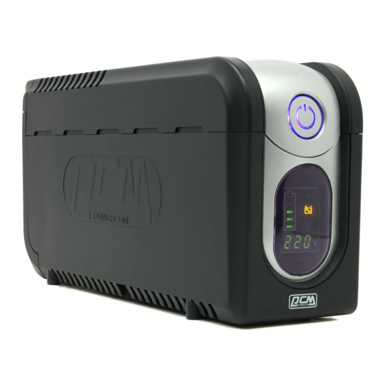
Summary of Contents for Farnell Imperial Series IMP-425AP
- Page 1 Imperial Series Model IMP-425/525/625/825/1000AP IMD-425/525/625/825/1000AP IMP-1025/1200/1500/2000AP IMD-1025/1200/1500/2000AP...
-
Page 2: Table Of Contents
Contents of Service Manual 1. Safety Precautions ------------------------------------------------------------------ 2 1.1 Service Warnings ----------------------------------------------------------------- 2 Important Safety Instructions --------------------------------------------------- 2 2. General Information ------------------------------------------------------------------ 3 2.1 Outline ------------------------------------------------------------------------------ 3 2.2 Features ----------------------------------------------------------------------------- 3 3. SPECIFICATIONS ------------------------------------------------------------------- 5 3.1 Electrical Specifications ----------------------------------------------------------- 5 3.2 Mechanical Specifications--------------------------------------------------------- 7 3.3 Environmental Specifications ----------------------------------------------------- 7 Communications Interface ------------------------------------------------------- 8... -
Page 3: Safety Precautions
1. Safety Precautions 1.1 Service Warnings * The UPS contains voltages what are potentially hazardous. All repairs should be performed by qualified service person. * The UPS has its own internal energy source (battery). The output receptacles may be alive even when the UPS is not connected to an AC supply. -
Page 4: General Information
2. General Information 2.1 Outline The Imperial Series are advanced line-interactive simulated sine wave uninterruptible power systems (UPS) designed to prevent spikes, surges, sags, transients and blackouts from reaching your sensitive equipment. Your equipment may include such items as computers and computerized instruments to telecommunication systems. - Page 5 UPS provides significant savings and gives the UPS an almost unlimited life. You can replace the battery very easily, and without turning off your UPS or the equipment it is protecting. Advanced Interface to Communicate with Computer Many UPS’s provide only a basic power failure warning.
-
Page 6: Specifications
3. SPECIFICATIONS 3.1 Electrical Specifications Battery output rating Product Name Frequency Rated Voltage Capacity (Hz) 100 / 110 / 115 / 120V IMP/IMD-425AP 50/60 255W 220 / 230 / 240V 100 / 110 / 115 / 120V IMP/IMD-525AP 50/60 315W 220 / 230 / 240V 100 / 110 / 115 / 120V IMP/IMD-625AP... - Page 7 Wave Form Sine wave AC Mode Back Up Mode Step wave Transfer time ⇒ 4 ms (typical) Power Failure AC Inverter Spike/Surge protection Version Continuous Single pulse 8/20us Voltage Vrms Imax Joules 100/110/115/120V 175V 6,000A 1050max. 220/230/240V 385V 6,000A 1050max. Audible Alarm Battery discharge at power failure Beep every 2 seconds...
-
Page 8: Mechanical Specifications
Mechanical Specifications: Product Name Dimensions Weight (Kg) W × D × H (mm) Shipping IMP/IMD-425AP 105*334*168 105*334*168 IMP/IMD-525AP IMP/IMD-625AP 105*334*168 IMP/IMD-825AP 105*334*168 105*334*168 IMP/IMD-1000AP IMP/IMD-1025AP 130*382*192 13.4 14.8 IMP/IMD-1200AP 130*382*192 13.4 14.8 IMP/IMD-1500AP 130*382*192 13.6 15.0 IMP/IMD-2000AP 130*382*192 14.5 15.9 Environmental Specifications: Operating Storage and Shipment... -
Page 9: Communications Interface
4. Communications Interface The communication port on the rear panel of the UPS allows for connection to a host computer. When used with UPSMON communication software you will have access to important operating information. From your computer screen, you can monitor input/output voltage, AC frequency, battery voltage, etc., and analyze power problems. - Page 10 Dsub9 Pin assignments: Pin No. RS-232 Signal Contact Closure Signal Tx (UPS > Computer) Rd (Computer > UPS) Shut Down +12V (Computer > UPS) AC failure -12V (Computer > UPS) Battery Low Tx (Short with pin2 )
-
Page 11: Battery Replace Procedure
5. Battery Replace Procedure Changing the batteries in your UPS is a safe and easy procedure. Since the battery is not isolated from the AC input, you must power off your UPS and unplug the power cord before proceeding the following procedure. 5.1 Replacement Procedure for IMP/IMD-425~1000AP (Optional function) 1. -
Page 12: Replacement Procedure For Imp/Imd-1025~2000Ap
5.2 Replacement Procedure for IMP/IMD-1025~2000AP Remove the screws on the battery cover. Pull and open the cover. Remove the screws of the battery retaining plate. Pull out the battery. Disconnect the two wires connecting the battery pack to the UPS Connect the wires to the new battery pack, making sure that the red wire is connected to the red battery terminal and the black wire is connected to the black battery terminal. -
Page 13: Disassembly Procedure
6. Disassembly Procedure 6.1 Disassembly procedure for IMP/IMD-425~1000AP 6.1.1 Top Cover Removal * Turn the UPS off and unplug it from the utility line. * Remove the 6 screws on the bottom. * Open the top cover. 6.1.2 Remove the battery wire * Remove the black wire from PCB to battery. -
Page 14: Disassembly Procedure For Imp/Imd-1025~2000Ap
6.2 Disassembly procedure for IMP/IMD-1025~2000AP 6.2.1 Top Cover Removal * Remove the 8 screws on the bottom and rear panel. * Take off the top cover. 6.2.2 Batter Removal * Turn the UPS off and unplug it from the utility line. * Remove the front panel and disconnect the LED wire. -
Page 15: Test & Adjustment Procedure
Test & Adjustment Procedure This Procedure outlines the steps to functionally test the IMP/IMD-425AP~2000AP models. The functional test is broken down into several sections to test each different function of the UPS. 7.1 Charger Voltage Test * Plug the UPS into an AC power source and turn the UPS on. * Disconnect positive (red) battery wire. -
Page 16: Transfer Point Test
7.3 Transfer Point Test * Using a variac, set the output for the rated UPS's voltage. * Slowly reduce the variac output while monitoring the UPS's input voltage. The UPS should transfer to Boost when the voltage drops to the level given in the following Transfer Point Chart. Repeat this procedure to ensure accurate results. -
Page 17: Function Block Diagram
Function Block Diagram 8.1 Main structure 8.2 Control circuit... -
Page 18: Troubleshooting
9. Troubleshooting Problem Possible Cause Action to take UPS can’t turn on Switch on the display board fail Replace the display PCB ( LED not light) Per Battery voltage less than 9V Recharge the ups at least 8 hours, or change the battery.

Need help?
Do you have a question about the Imperial Series IMP-425AP and is the answer not in the manual?
Questions and answers