Table of Contents
Advertisement
Advertisement
Table of Contents

Related Manuals for Power Master SRFW-250E

Summary of Contents for Power Master SRFW-250E
- Page 1 Instruction Manual Gasoline Welding Generator...
-
Page 2: Table Of Contents
TABLE OF CONTENTS: 1. GENERAL SAFETY INFORMATION 2. ELECTRICAL SAFETY INFORMATION 3. SAFETY STICKERS AND EXPLANATIONS 4. CONTROL IDENTIFICATION 5. PRE OPERATING INSPECTION 6. STARTING THE ENGINE 7. USING THE GENERATOR 8. USING THE WELDER 9. ACTUAL WELDING 10. STOPPING THE ENGINE 11. - Page 3 IMPORTANT: Thank you for purchasing a Power Master Gasoline Welder Generator (hereinafter referred to as the “welder generator”). This manual will assist you in operating and maintaining your welder generator. This manual is the latest version. With the continuous improvement and upgrading of this product, the manufacturer reserves the right to modify this manual without notice.
- Page 4 IMPORTANT NOTICES: PLEASE PAY SPECIAL ATTENTION TO STATEMENTS PRECEDED BY THE FOLLOWING WORDS: Danger • DANGER This indicates a hazardous situation, which, if not avoided, will result in death or serious injury. Warning • WARNING: This indicates a hazardous situation, which, if not avoided, could result in death or serious injury.
-
Page 5: General Safety Information
1. GENERAL SAFETY INFORMATION: Danger Warning Caution 1.1. A “LAYMAN” and or “CHILDREN” may not recognize the possible dangers of operating a Welder Generator. We recommend that only competent persons should operate the Welder Generator. 1.2. Fuel is combustible and easily ignited. Do not refuel during operation. 1.3. -
Page 6: Electrical Safety Information
schedule in the operator manual. 1.9. Always use a face shield/welding mask when welding with the Welder Generator. Your face and eye protection is of the utmost importance. 1.10. Looking at a welding arc may cause damage and or severe pain to your eyes and even possible temporary blindness. - Page 7 the Welder Generator. If a circuit breaker requires replacement, it shall be replaced by a circuit breaker that has identical ratings and performance characteristics. 2.5. Due to high mechanical stresses only tough rubber-sheathed flexible cable should be used 2.6. If the Welder Generator is of Class II construction then earthing of the Welder Generator is not required.
- Page 8 2.7.6. A 4mm2 flexible cable can draw a maximum of 10a provided that the cable is not longer than 100m 2.7.7. A 4mm2 flexible cable can draw a maximum of 16a provided that the cable is not longer than 65m VOLTAGE DROP IN ELECTRIC EXTENSION CORDS When a long electric extension cord is used to connect an appliance or tool to the generator, a certain amount of voltage drop or loss occurs in the extension cord which reduces the effective...
-
Page 9: Control Identification
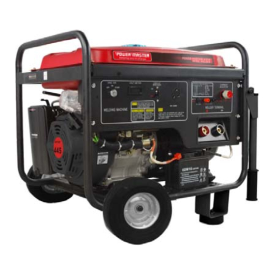
CONTROL IDENTIFICATION: 1. Welding transform switch 2. Choke lever 3. Air-Cleaner 4. Positive pole 5. Negative pole 6. DC 7. Current regulator 8. Socket 9. Circuit Breaker 10. Volt meter 11. Engine Switch... -
Page 10: Pre Operating Inspection
5. PRE OPERATING INSPECTION: Caution 5.1. Engine Oil – This is a major factor affecting the performance and life span of the Welder Generator. Do not use non-detergent and 2 stroke oil as this will damage the Welder Generator. 5.2. Before using the Welder Generator check the oil level, ensure that the unit is on a flat and level surface when doing this and that the unit is “OFF”... - Page 11 5.8. Always refuel in a well ventilated area. 5.9. Do not attempt to refuel the Welder Generator whilst the engine is running. 5.10. Be careful not to over fill the tank when refueling. If this happens, clean the fuel spillage properly.
-
Page 12: Starting The Engine
6. STARTING THE ENGINE: 6.1. Turn the circuit breaker to the “OFF” position. 6.2. Set the auto-throttle switch to the “OFF” position 6.3. Open the fuel cock 6.4. Push the chock lever to the “CLOSED position Caution Do not use the choke if the engine is warm 6.5. -
Page 13: Using The Welder
7.4. Turn the aut0-throttle switch to the “OFF” position Warning Do not overload your generator, only load up to the rated power under the rated ambient conditions. Note that operating your generator in extreme humidity and temperatures or in an environment that is not well ventilated will affect the performance and a reduction in power will be noticed. - Page 14 correct electrode diameter and current making reference to the table below: TABLE 1: PLATE THICKNESS (mm) ELECTRODE DIAMETER (mm) CURRENT SETTING(A) 2.0 – 3.0 50 - 80 3.0 – 4.0 70 - 120 4.0 – 6.0 110 - 170 >7.0 140 - 210 9.2.
-
Page 17: Stopping The Engine
10. STOPPING THE ENGINE: 10.1. Stopping the engine whilst in the “generator” function: 10.1.1.1. Turn the circuit breaker to the “OFF” position 10.1.1.2. Disconnect the load from the AC receptacle 10.1.1.3. Turn the key to the “OFF” position 10.1.1.4. Turn the fuel cock off 10.2. - Page 18 If the engine will still not start then contact Gentech Industries for technical assistance. The details are on the back page of this operators manual. 11.2. No electricity/voltage at the AC Receptacles: 11.2.1.1. Check if the circuit breaker is in the “ON” position. Turn to the “ON” position if necessary. 11.2.1.2.
- Page 20 12. Engine Oil: 12.1.1.1. Remove the oil filter cap and check the oil. 12.1.1.2. Remove the drain plug and allow the oil to drain out. Ensure that the oil is drained into a disposable container. 12.1.1.3. Remove the drain plug and allow the oil to drain out. Ensure that the oil is drained into a disposable container.
- Page 21 Please ensure that when replacing, it is replaced with the same size. 12.3. Air Filter: 12.3.1. Remove the air filter from the air filter casing/cover. 12.3.2. Take the filament out of the housing. 12.3.3. If the core is dirty then wash it in kerosene, squeeze it before soaking it in engine oil. Before replacing squeeze out the excess oil.
-
Page 22: Transporting And Storage
TRANSPORTING AND STORAGE 13.1. Before transporting the Welder Generator please ensure that the fuel cock is in the “OFF” position. Caution Contact with a hot engine or exhaust system can cause severe burns and or fires, always allow for the engine to cool down prior to transporting and or storing. Always ensure that the Welder Generator is transported and or stored in a flat horizontal position. - Page 23 13.2. Before storing the welder generator for an extended period of time please ensure that the area of storage is free from excessive dust and humidity. Please follow the table below: STORAGE TIME RECOMMENDED MAINTENANCE • 0 – 1 MONTH NO PREPARATION REQUIRED •...
-
Page 24: Technical Specification And Data
14. TECHNICAL SPECIFICATION AND DATA: MODEL SRFW-250E ENGINE MODEL SR192FE DISPLACEMENT CC IGNITION SYSTEM NON CONTACT TRANSISTOR STARTING SYSTEM ELECTRIC GENERATOR RATED OUTPUT (KVA) MAX OUTPUT (KVA) RATED VOLTAGE (V) RATED POWER FACTOR (COS) PHASE SINGLE WELDER RATED VOLTAGE (V) 22-28 CURRENT ADJ. - Page 26 POWER MASTER……………………………… KEEPING YOU IN CHARGE GENTECH INDUSTRIES, OFFICIAL SERVICE AGENTS.
Need help?
Do you have a question about the SRFW-250E and is the answer not in the manual?
Questions and answers