
Related Manuals for Sine Systems RP-8

Summary of Contents for Sine Systems RP-8
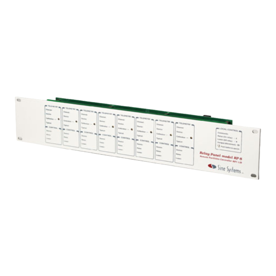
- Page 1 Remote Facilities Controller Model RFC-1/B • Relay Panel Model RP-8 – INSTALLATION AND OPERATION – Remote Facilities Controller firmware version 6.00 www.sinesystems.com...
-
Page 2: Table Of Contents
Section 2 – New Features and System Changes Version 6.00 Section 3 – Installation System Includes Installing the System Mechanical Installation RFC-1/RP-8 Interconnect RP-8 Channel Block Assignment RP-8 Telemetry Connections RP-8 Control Connections RP-8 Channel Identification Telephone and Telephone Line Connection Power Supply Telemetry Source Inputs... - Page 3 Auxiliary Circuits Audio Detection Latching Relays Telemetry Pulse Stretching Battery Backup Section 5 – Basic Operation Overview Operation from the Local Telephone Connecting to the RFC-1 Selecting a Channel Reading Telemetry Channels Operating the Control Relays Issuing other Commands Disconnecting from the RFC-1 Operating from a Remote Telephone Connecting to the RFC-1 Operating the RFC-1...
- Page 4 Clock and Calendar 6.12 Setting the Calendar 6.12 Day of the Week 6.12 Setting the Clock 6.12 Automatic Daylight Saving Time Adjustment 6.12 Clock Calibration 6.13 Action Sequences 6.15 Fixed-programming Action Sequences 6.15 User-programmable Action Sequences 6.16 Control Relay Operation 6.17 Action Sequence Delays 6.18...
- Page 5 Section 8 – Troubleshooting and Service Common Problems and Possible Solutions Factory Service Policy Section 9 – Specifications Electrical and Mechanical RFC-1 Remote Facilities Controller RP-8 Relay Panel Schematic Diagrams Appendix A – Programming Address Table 0000 Telemetry Channels 0256...
-
Page 6: Section I - Safety Information
Depending on the installation, the control circuits of the RP-8 Relay Panel may be connected to sources of up to 120 volts AC and/or several amperes of current. Under certain conditions, these voltage sources can be lethal. Always use caution when working around these circuits. -
Page 7: Fcc Compliance
Also, you will be advised of your right to file a complaint with the FCC if you believe it is necessary. Please contact Sine Systems, Inc., for repair and/or warranty information if you suspect that the RFC-1 has malfunctioned. If a defective device is causing harm to the telephone network, the telephone company may request you remove that device from the network until the problem is resolved. -
Page 8: Section 2 - New Features And System Changes
Section 2 — New Features and System Changes Version 6.00 General Feature Updates The RFC-1 can reset all user programmable settings to their factory default values. A special advanced programming code has been added to the system that performs this operation. The system can be manually forced to both data and voice mode with the command 84. - Page 9 Telemetry System Updates Telemetry channels that are programmed as status channels (“on/off”, “normal/alarm”, etc.) can be individually programmed to invert the status reading. Typical behavior is a reading of “off” when no voltage is present and “on” when voltage is present. The readings can be swapped so that no voltage reads “on” and voltage present reads “off”. This eliminates the need for wiring an external inverter circuit.
- Page 10 Alarm System Updates The telemetry alarm channel scanning intervals have changed. The factory default scan interval is still one channel per 10 seconds. Several new intervals have been added including a shorter 5-second interval as well as a very long 240-second interval.
-
Page 11: Section 3 - Installation
Operation manual • All systems are fully tested before leaving the factory but damage may occur in transport. When the RFC-1 and RP-8 panels are unpacked, they should be inspected for obvious signs of mechanical damage or loose parts. Loose parts should be tightened before installation. -
Page 12: Mechanical Installation
The RFC-1 should be connected to the RP-8 relay panel(s) with the 16 conductor flat (ribbon) cable. This cable is supplied with the RFC-1. The cable is terminated with one connector at each end. If more than one RP-8 is used in a system, an extra connector will be supplied with the additional RP-8. -
Page 13: Channel Block Assignment
If your system uses only one RP-8 you may skip this section. Each RP-8 panel in the system should be assigned to a different “block” of eight channels. The channel blocks are: 00-07, 08-15, 16-23, 24-31, 32-39, 40-47, 48-55 and 56-63. Normally, consecutive blocks of channels are used but this is not necessary. -
Page 14: Telemetry Connections
3.2.4 RP-8 Telemetry Connections Telemetry connections to the RP-8 are made through two-conductor screw terminal connectors. The screw terminal connectors can be removed for easier installation. There are no locks or catches, grasp the connector firmly and pull it away from the panel. -
Page 15: Control Connections
RP-8 Channel Identification The front of the RP-8 includes a place to record pertinent data regarding each channel. Remember, the channels read in the correct order from the back of the panel when wiring. Channels read right to left as viewed from the front of the panel—the lowest channel number is on the far right. -
Page 16: Telephone And Telephone Line Connection
Power Supply Power to operate the RFC-1 and up to eight RP-8 panels is supplied by a 12 volt AC wall-plug transformer that is supplied with the RFC-1. This transformer is designed for 120 volts AC at 50-60 Hz and is rated at 1 amp. The leads of this transformer should be stripped and connected to the screw terminal connector marked “12 VAC”... -
Page 17: Telemetry Source Inputs
Telemetry inputs are located across the top of the RP-8 panel through the 8 two conductor terminal blocks marked “Telemetry”. The channels are identified as “00” through “07”. In situations where more than one RP-8 is used, channel numbers increase by 8 on each successive relay panel. -
Page 18: Analog Readings
DC. A single power supply can be used for many status contacts. The external 1 KΩ resistor is added to discharge the input smoothing capacitor on the RP-8 more quickly. Without this resistor it takes about 5 seconds to reach a “status off”... -
Page 19: Calibrating Telemetry Readings
AC sample. The low voltage AC can then be routed through a series diode and resistor (approximately 1 KΩ) to the telemetry input. The 10 µF capacitor on the RP-8 should provide sufficient filtering. -
Page 20: Control Outputs
The control relays on the RP-8 are momentary relays that operate as long as the control commands (* or #) are sent to the RFC-1. An external latching relay must be used if maintained outputs are required. The appropriate output relay of the RP-8 can be used to provide a control signal to the latching relay. -
Page 21: Dedicated Control Port
3.5.3 Radiotelephones and Wireless Extenders This class of device uses a full duplex radio circuit to extend a POTS telephone line over a radio link. Two small transceivers are used. One is connected to the telephone line and the remote device emulates the telephone line. Radiotelephones have a range of roughly 1 to 20 miles depending on terrain. - Page 22 If the DC blocking capacitors are not used, however, two conditions must be satisfied: No more than about 50 mA DC should be drawn from this port—this is an equivalent DC load • resistance of about 240 ohms No DC load, and only a high impedance AC load, should be present across this port when the •...
-
Page 23: Battery Backup And Clock/Calendar
Battery Backup and Clock/Calendar All of the user options and programmable parameters of the RFC-1 are stored in non-volatile memory that remains intact if power is interrupted. The clock/calendar requires continuous power and the system will lose the time and date if power is lost. -
Page 24: Telephone Line Protection
It mounts directly to the RP-8 Relay Panel. Damage to the RFC-1 and RP-8 by lightning is not covered under warranty. See the complete warranty for more information. -
Page 25: Section 4 - Accessories And Miscellaneous Circuit
SIP-8 Status Input Panel Similar to an RP-8 and not to be confused with the surge protector that has a similar model number, the SIP-8 offers eight status-only inputs. Unlike the inputs of the RP-8 that require an external voltage source, the SIP-8 inputs are activated by a switch or relay closure from an external device. -
Page 26: Intelligent Rack Adapter
Filter circuits in the ACM-2 average the alternating current so that a steady reading is available even when flashing beacons are used. The DC output connects to a telemetry channel on the RP-8. In most cases, the resolution of the ACM-2 is more than sufficient to detect the failure of one bulb in a lighting system. -
Page 27: Auxiliary Circuits
Auxiliary Circuits Accessories are available that give the RFC-1 extra capabilities. Some functions are simple to add with just a few extra parts. 4.2.1 Audio Detection In some cases it is desirable to monitor the presence or loss of an audio signal with the RFC-1. This signal can be used to trigger an alarm in the RFC-1. -
Page 28: Latching Relays
4.2.2 Latching Relays Some devices may require a maintained relay contact for proper operation. While the RFC-1 cannot provide a maintained relay contact, it is not difficult to use the control relays of the RFC-1 to electrically latch an outboard relay. The disadvantage of this type of latched relay is that if power fails the relay may chatter or change state. - Page 29 4.2.2.1 Rising Edge Detection Circuit Part Description 74HC123AN retriggerable timer IC C1-C2 0.1µF 50V monolithic ceramic capacitor* 5K Ohm ¼ W carbon film resistor* 1M Ohm ¼ W carbon film resistor Power 5VDC regulated power supply Figure 4.3; Circuit to detect and extend a rising edge pulse 4.2.2.2 Falling Edge Detection Circuit Part Description...
-
Page 30: Battery Backup
4.2.3 Battery Backup Do not under any conditions apply a DC voltage greater than 19.9 volts (19.9 VDC peak if significant ripple is present) to the RFC-1. Prolonged exposure will cause the protection circuitry in the RFC-1 to overheat and be damaged. This maximum voltage rating precludes the use of some rechargeable batteries. -
Page 31: Section 5 - Basic Operation
Connecting to the RFC-1 Operation from the local phone is initiated by pushing the button labeled "Local Control" on the RP-8 relay panel. When the button is pressed, the RFC-1 activates the local phone and speaks the identification phrase "This is RFC- 1/B". -
Page 32: Reading Telemetry Channels
5.2.3 Reading Telemetry Channels Taking a telemetry reading is as simple as selecting a channel. The RFC-1 responds with the current telemetry value as soon as the channel is selected. For example, enter 03 on the keypad to take a reading on channel 3. The RFC-1 responds “Channel 03”... -
Page 33: Operating From A Remote Telephone
Operation from a Remote Telephone Operating the RFC-1 from a remote telephone is very much like operating it from the local phone. The primary difference is that the connection is made from a remote location through a telephone line. A user dials the telephone number at the site where the RFC-1 is installed. -
Page 34: Alarm System
Alarm System The RFC-1 can monitor up to eight channels for abnormal telemetry conditions. If an out-of-tolerance condition is detected, the system will call up to four telephone numbers to notify an operator of the condition. In basic operation, the RFC-1 calls an operator but it does not attempt to correct the situation without user intervention. 5.4.1 How the Alarm System Works After the alarm channels have been setup, the RFC-1 compares the current telemetry reading on the channel against... -
Page 35: Programming Alarm Limits
5.4.3 Programming Alarm Limits The eight alarm channels are designated as A through H. One telemetry channel can be assigned to each alarm. It is not necessary to use all the alarms nor is it necessary to program them in order. For example, alarm A might monitor telemetry channel 07 and alarm B could monitor telemetry channel 03 while alarms C-H are left unused. -
Page 36: Enabling / Disabling The Power Failure Alarm
5.4.6 Enabling / Disabling the Power Failure Alarm The RFC-1 can alert an operator of an AC power failure at the remote site. In most cases, this alarm triggers when AC power returns. The RFC-1 uses the same dialing procedure as it does for telemetry alarms as described in section 5.4.1 but the message delivered is “This is RFC-1/B. -
Page 37: Clock And Calendar
If there is not a generator and a UPS is not used, when AC power fails at a site, both the RFC-1 and the transmitter lose power. When power returns, the RFC-1 makes a new reference scan. If the transmitter does not power up automatically, the reference scan will show that the power off condition is normal and no alarm will trigger. -
Page 38: Basic Programming
Basic Programming The RFC-1 can be programmed to suit the individual needs of the installation and its operators. Alarm parameters, telephone numbers, security codes, etc. are all programmable. Most of the settings in this section can be changed from either the local phone or a remote telephone. For safety and security, a few options are only available from the local phone. -
Page 39: Operating Commands / Notes
Operating Commands / Programming Notes It may be helpful to keep a table of normal programming for the RFC-1. This serves not only as a reminder of the current programming but it also acts as a handy guide to remember how to change some common system settings. Command Function Factory Setting... -
Page 40: Section 6 - Advanced Operations
Section 6 — Advanced Operation This section is for qualified technical personnel. It contains information to alter most operating characteristics of the RFC-1 system. Improper use of this information can cause unexpected or undesirable behavior. We strongly recommend having a full understanding of the basic operation of the RFC-1 and the specifics of the installation before applying this information. -
Page 41: Programming Address Table
6.2.1 Programming Address Table In the appendix of this document there is a list of all memory addresses with descriptions of what feature is controlled at each address—the Programming Address Table. This list is the key to programming mode in the RFC-1. It translates the memory address numbers that the RFC-1 uses into a descriptive map. -
Page 42: Using The Programming Mode
6.2.2 Using the Programming Mode The programming method is the same for setting up any feature using programming mode. Different address and data tables are used for each feature but every address is programmed the same way. Programming mode temporarily suspends normal system activity—telemetry channels are not selected and control relays do not activate. -
Page 43: Restore Factory Settings
6.2.3 Restore Factory Settings In programming mode there is a special extension command that will reset the RFC-1 back to the factory default settings. This command will restore all programmable items to the factory settings including security codes, alarm values, date and time functions, channel settings, telephone numbers, site ID phrase, etc. To restore the factory settings in the RFC-1: Enter programming mode: 80 At the prompt, enter the advanced programming security code: 4150... -
Page 44: Telemetry Channels
Telemetry Channels Incorrect use of the following information can cause unexpected or undesirable behavior. We strongly recommend that you understand the basic operation of the RFC-1 and the specifics of the installation before continuing. If you have not done so already, please read the documentation above that describes the Advanced Programming Mode before continuing. -
Page 45: Status Readings
6.3.3 Status Reading Status channels are programmed like the unit words above but they are treated as a special case. The first 16 words in the Word Table (words 0-0 through 0-15) are numbers. Assigning a number as a unit word would be confusing. Instead, those values behave according to the table below. -
Page 46: Maximum Scale And Decimal Point
6.3.4 Maximum Scale and Decimal Point Setting an appropriate scale allows the RFC-1 to give a more accurate reading. When choosing the scale, find the smallest item in the table below that is larger than the highest expected reading. Be sure to allow some headroom for out of tolerance readings. -
Page 47: Indirect Power
This is referred to as an indirect power calculation. This feature requires careful setup to work properly. Sine Systems provides a web page that will perform the appropriate calculations and generate values to program into the RFC-1. The web site is http://www.sinesystems.com. Navigate to the tech support section for the RFC-1 and follow links to the Indirect Power Calculation page. - Page 48 6.3.6.a Indirect Power—Theory of Operation This section provides further information on calculating indirect power. If the sequence above is completed and it operates successfully then it is not necessary to read this section. This information is useful for troubleshooting. An indirect power channel has a reading from 0000 to 9999. A decimal point is optional and the unit word will be either “kilowatts”...
-
Page 49: Telemetry Leading Zero Suppression
6.3.7 Telemetry Leading Zero Suppression Telemetry values in the RFC-1 are four-digits long. A channel should be calibrated to take advantage of as much of the telemetry scale as possible for maximum accuracy. Sometimes a telemetry reading will have a zero as the left most zero in part of its operating scale. -
Page 50: Number Of Telemetry Channels Available
6.3.9 Number of Telemetry Channels Available The RFC-1 can support up to 8 relay Panels. Each relay panel has 8 channels. Memory addresses must be available for all 64 possible channels even though most RFC-1 systems use fewer than that. Rather than leave the memory for unused channels empty and potentially wasted, that memory space can be used for more date/time triggers. -
Page 51: Clock And Calendar
Clock and Calendar The clock and calendar are used by the RFC-1 to trigger events by the date and time. Enhancements to the timing system give the RFC-1 very good long-term accuracy. The clock will attempt to synchronize with the AC main supply when the RFC-1 is powered from either a 50 Hz or 60 Hz AC supply. -
Page 52: Clock Calibration
This feature is enabled or disabled in programming mode at address 1017. The table below shows available options. Automatic Daylight Saving Time Change Disabled—no automatic change Enabled—DST clock adjust (factory setting) Automatic DST time change is enabled when shipped from the factory. Follow the instructions below to disable it. Enter the Advanced Programming Mode: 80 Enter the Advanced Programming Security Code: 4150 Enter the address (from the Address Table) for the Auto DST function: 1017... - Page 53 The clock gains time when it runs too fast. Suppose the clock is set to a known accurate time. Six days later at 6:00 pm the RFC-1 clock is checked. Instead of 6:00 pm it reads 6:01 pm. It is running too fast and has gained 1 minute. Positive numbers in the table below make the clock run slower.
-
Page 54: Action Sequences
Action Sequences Functional knowledge of the specific installation is required to make use of the information presented here. In addition, some degree of comfort working with the RFC-1 is presumed in the documentation that follows. The RFC-1 can be programmed to respond to telemetry conditions or the time and date. These automatic functions rely on action sequences—series of instructions stored in memory to perform a specific task or set of tasks. -
Page 55: User-Programmable Action Sequences
6.5.2 User-programmable Action Sequences The RFC-1 can store up to 8 action sequences having up to 8 steps each. The available instructions are listed in the text that follows along with a unique code that identifies each instruction. Select the instructions and program the corresponding codes in the appropriate area of memory for the action sequence. -
Page 56: Control Relay Operation
6.5.3 Control Relay Operation The RFC-1 can operate any of the control relays as a step in an action sequence. Select an instruction from the list below and program V1 and V2 in the action sequence to activate the associated control relay. Control relays are momentary activation only. -
Page 57: Action Sequence Delays
6.5.4 Action Sequence Delays The RFC-1 pauses for about one-half second between the steps of an action sequence. This can be adjusted in an individual action sequence by placing a delay instruction at the appropriate point(s) in the action sequence. Delay instructions can be used in succession to create a longer delay. -
Page 58: Alarm Calls
6.5.5 Alarm Calls The RFC-1 can place telephone calls as a step in an action sequence. The message delivered depends on the condition that triggers the action sequence. The message typically consists of the site identification phrase followed by an indication of the condition that triggered the call such as a telemetry alarm or power failure. The message repeats for a pre-determined length of time. -
Page 59: Logging Telemetry Readings
6.5.6 Logging Telemetry Readings The RFC-1 can send a set of telemetry readings to a printer or computer as a step in an action sequence. The logging device can be connected directly to the RFC-1 or at a remote location. The set of readings will start with channel 00 and end at the programmed auto-scan stop channel. -
Page 60: Conditional Execution
6.5.7 Conditional Execution There are no instructions in the RFC-1 action sequences for performing loops or making complex decisions. These kinds of functions are simply beyond the capabilities of the available memory and processing power. However, there are some instructions that can be used to perform simple conditional behavior. Description Stop execution and recheck telemetry This instruction stops execution of the action sequence and rechecks the telemetry on the channel... - Page 61 An example is the easiest way to illustrate how this works. Suppose the telemetry input on channel 01 is a transmitter output power sample. An alarm is programmed to monitor channel 01 so that if the transmitter power goes too high, the RFC-1 will adjust it down into limits. The RFC-1 control relays are momentary activation, about one-half second.
- Page 62 In this example, the RFC-1 has been programmed to make the power changes automatically. At the appropriate times of day the RFC-1 will execute an action sequence activating relays as needed to change the transmitter power. When the sequence terminates a new reference reading is made for the alarms. If for some reason the transmitter does not change power, the RFC-1 will record the current reading as the reference and it will be considered normal even if it is out-of-tolerance.
-
Page 63: Enabling / Disabling Telemetry Alarms
6.5.8 Enabling / Disabling Telemetry Alarms Telemetry alarms can be selectively enabled and disabled by an action sequence. This is particularly useful for transmitters that operate at multiple power levels. The appropriate alarm can be enabled using the same action sequence that changes the transmitter power. -
Page 64: Testing An Action Sequence
6.5.10 Testing an Action Sequence Action sequences are typically activated by telemetry alarms or by date/time triggers. However, it is possible to trigger an action sequence manually for testing purposes or for ease of system use. Suppose an action sequence is programmed to adjust an antenna switch and change transmitter power. The action sequence can be used to perform the procedure manually. -
Page 65: Telemetry Alarms
Telemetry Alarms Incorrect use of the following information can cause unexpected or undesirable behavior. We strongly recommend that you understand the basic operation of the RFC-1 and the specifics of the installation before continuing. Please read the documentation above that describes the Advanced Programming Mode before continuing if you have not done so already. -
Page 66: Trigger Rules
6.6.3 Trigger Rules The trigger rule determines the conditions under which the alarm activates—which alarm limits are critical. The default trigger rule is adequate in most cases as long as the alarm limits are set properly. Program the value from the column V1 into the third memory location for the selected alarm. -
Page 67: Upper And Lower Limits
6.6.5 Upper and Lower Limits The upper and lower limits specify the range of acceptable telemetry values for a channel. Limits are programmed using 4 digits. If the telemetry channel reading has a decimal point, ignore the decimal but keep the digits following the decimal. -
Page 68: Blocking Alarms By Time
6.6.7 Blocking Alarms by Time It is possible to disable a telemetry alarm during certain hours of the day by programming an alarm block. Alarm blocks are used in cases where an alarm is not valid during part of the day. Tower light monitoring is a good example. -
Page 69: Alarm Scan Interval And Sequence
Each hour setting uses 2 memory addresses. Program the first digit of the hour at the location listed as “V1” and program the second digit at the memory location listed as “V2”. Do this with both the start and stop hours. The example below shows programming for an alarm block that is active every day of the week in every month from 8:00pm (20 hours) to 6:00am (06 hours). -
Page 70: Timed Events
Timed Events Incorrect use of the following information can cause unexpected or undesirable behavior. We strongly recommend that you understand the basic operation of the RFC-1 and the specifics of the installation before continuing. Please read the documentation above that describes the Advanced Programming Mode before continuing if you have not done so already. -
Page 71: Programming A Timed Event
Looking at the Programming address table, the date/time triggers appear to be numbered backward. As the address increases—the normal direction for programming—the number of the date/time trigger decreases. This is not a mistake. The numbering is consistent as the date/time triggers transition into shared memory. This selection from the Programming Address Table highlights the transition—notice the Alternate Use column. -
Page 72: Special Triggering Options
6.7.5 Special Triggering Options The RFC-1 has settings that simplify programming for events that repeat on easily defined intervals. A single date/time trigger will trigger an event using the specified interval(s). Program V1 and V2 from the table below for date value 1 and 2 to trigger an event on the specified days of the week. Day(s) of the Week Day(s) of the Week Monday... - Page 73 The previous example can be altered to print every day at 6:00 am. The programming is shown below. - Programming - Addr Description Section Default Current Alternate Use / Notes 0632 Date/time trigger 1: action sequence 6.6.4 Alarm block 1: block indicator 0633 Date/time trigger 1: month 6.6.4...
- Page 74 Suppose we need to turn a transmitter on every day at 5:30 am in April and that action sequence 3 is programmed to perform this task. We will use date/time trigger 1 but any unused date/time trigger will work. - Programming - Addr Description Section...
-
Page 75: Telemetry Auto-Scan Data Interval
6.7.7 Telemetry Auto-scan Data Interval The telemetry auto-scan data feature provides logging data at fixed intervals. It is a timed event that operates very much like a date/time trigger event but it is a very specialized case. First, it is not programmed in the same area of memory as the other date/time triggers. -
Page 76: Communication
Communication Incorrect communication settings can cause the RFC-1 to place repeated, unwanted calls to unsuspecting people or places. It is solely your responsibility to verify that the RFC-1 is programmed to contact only authorized personnel. 6.8.1 Programming Telephone Numbers The six telephone numbers stored in the RFC-1 are designated as Telephone Number A-F. Each telephone number contains up to twelve digits. -
Page 77: Extending Telephone Numbers
6.8.2 Extending Telephone Numbers When more than twelve digits are needed for a single call, two (or more) telephone numbers can be chained together to form one longer telephone number. Program the final digit of a telephone number with the value 15 as an indicator to continue dialing the next telephone number. -
Page 78: Setting The Call Mode
6.8.4 Setting the Call Mode Each telephone number has an associated dialing mode. This setting determines how the number is dialed: in voice mode, data mode or pager mode. There are two pager modes: pager mode and legacy pager mode. Pager mode supports many features of modern paging systems. -
Page 79: Calling Pagers In Voice Mode
6.8.4.3 Calling Pagers in Voice Mode The RFC-1 can call a text pager in data mode or in voice/DTMF mode. Calling a pager in voice mode does not require extra hardware. The pager message will consist of a programmable site ID number and, optionally, the number of the telemetry channel that triggered the alarm. -
Page 80: Calling Pager In Data Mode
In the example below, the telephone number for the pager is 555-1212 and the site ID that will be sent to the pager is 615-228-3500. The optional ❊ command is being used to add the channel number to the display and the # key is being sent to terminate the page. - Page 81 In this mode, the RFC-1 calls the paging terminal via modem. After the modems establish a connection, the RFC-1 sends a specially coded message to the paging terminal. The message includes the pager ID number to identify the message recipient and the message to be delivered to the pager. As in voice mode paging, data mode paging requires two telephone numbers.
-
Page 82: Tone/Pulse Dialing
6.8.5 Tone / Pulse Dialing The original RFC-1 hardware with the mechanical sounding voice only pulse dials. Later models that use the human- male sounding speech-processor perform tone dialing using the speech-processor. The tones are designed to compensate for component tolerances. More recent models have a dedicated hardware for generating DTMF tones. Use of the dedicated tone generator is recommended if hardware supports this feature. -
Page 83: Ring Sensitivity And Hang-Up Detection
6.8.8 Ring Sensitivity and Hang-up Detection Previous versions of the RFC-1 used a different, non-linear scale for the ring sensitivity adjustment. The scale below is only appropriate for systems running version 6.0 or higher. Using this data table to adjust earlier versions can cause unexpected and undesirable behavior. Attention! In previous versions of the RFC-1 the ring sensitivity setting shared a memory location with the dedicated control port feature. -
Page 84: Communication Mode
6.8.9 Communication Mode This adjustment sets the mode for incoming calls only. It has no effect on outgoing telephone calls. The communication mode determines what type of connections the RFC-1 receives for monitoring and control. It also determines whether the connection is part-time or full-time. A dial-up connection is typically part-time; the connection is broken at the end of the call. -
Page 85: Data Communication Settings
6.8.10 Data Communication Settings References in this section to paging terminals are strictly for full-text paging in data mode. This adjustment has no effect on voice mode paging. The data communication setting is determined by the device(s) that the RFC-1 will connect to in data mode. This adjustment sets the data format for incoming and outgoing connections. -
Page 86: Saving And Restoring System Settings
6.8.12 Saving and Restoring System Settings If the RFC-1 has a data accessory attached, the system settings can be copied to the connected device. If the device is a printer then a formatted list of the settings can be printed. If the device is a modem or terminal, software can collect the data and store it to a file. -
Page 87: Terminal Emulation Software
Save/Restore Data Dump The save/restore data dump copies the memory contents to the data port in a format that should be captured by a computer. The dump is a continuous feed of data from every address in order from 0000 to 1023. Each data byte is followed by a “#”... -
Page 88: Backing-Up System Settings
6.8.14 Backing-up System Settings The following instructions assume that you know how to connect and operate the RFC-1 in data mode with the installed data accessory. The examples use HyperTerminal in Windows. Other software and other computer platforms will work. Use appropriate terminal emulation software that is for the operating system. Using HyperTerminal to capture the RFC-1/B settings To backup the system settings, connect the terminal to the data port. -
Page 89: Restoring System Settings
6.8.15 Restoring System Settings The following instructions assume that you know how to connect and operate the RFC-1 in data mode with the installed data accessory. The examples use HyperTerminal in Windows. Other software and other computer platforms will work. Use appropriate terminal emulation software that is for the operating system. Using HyperTerminal to restore the RFC-1/B settings To restoring the system settings, connect the terminal to the data port. -
Page 90: Security Codes
Security Codes There are four security codes in the RFC-1. They are: the main security code, the control security code, the basic programming security code and the advanced security code. The easiest way to read and reprogram the security codes is using the prompted commands 72, 73, 74 and 75. They are described in section 5 of this document. For security reasons, the prompted commands only work from the local phone. -
Page 91: Incorrect Code Lockout / Communication Mode Switch Delay
6.9.3 Incorrect Code Lockout / Communication Mode Switch Delay The RFC-1 disconnects when an incorrect security code is given. This is a security measure to stop an intruder from making repeated attempts at guessing a code. The RFC-1 will ignore incoming calls for a short time period after a code fails. -
Page 92: Site Id And Other Options
6.10 Site ID and Other Options The section provides information on features that do not fall into any of the topics that have already been covered. 6.10.1 Site Identification Phrase The site identification phrase is what the RFC-1 uses to identify itself. This is the phrase that is spoken, or printed, when the RFC-1 comes online or when it calls out with an alarm notification. -
Page 93: Hardware Version
6.10.2 Hardware Version Incorrect hardware version settings can cause undesirable system behavior. If incorrect data is programmed, the RFC-1 seizes the telephone line making it impossible to call the system. Do not change this setting unless you are certain that it is required for your installation. The hardware revision is set at the factory and does not normally require adjustment. - Page 94 6.11 Operating Commands / Programming Notes It may be helpful to keep a table of normal programming for the RFC-1. This serves not only as a reminder of the current programming but it also acts as a handy guide to remember how to change some common system settings. Command Function Factory Setting...
-
Page 95: Section 7 - Programming Examples
Section 7 — Programming Examples This section contains programming examples. It does not contain information about using the Advanced Programming Mode of the RFC-1. You should be familiar with the section of this documentation that details Advanced Programming before using the examples in this section. You must be familiar with setup and operation of the RFC-1 for the information in this section to be useful. -
Page 96: Site Identification Phrase
Site Identification Phrase In the first example we will change the Site Identification Phrase—the phrase that the RFC-1 says when it answers the phone or when it reports an alarm. The factory programming is “This is RFC-1/B”. We will change it to say, “Hello this is Curly”. -
Page 97: Action Sequence
Action Sequence In this example we will program action sequence 2 to activate the channel 00 “on” relay, pause 15 seconds, and then activate the channel “01” on relay. A sequence like this might be used to power up transmitter filaments with a short delay then turn on the plate voltage. -
Page 98: Date/Time Trigger
Date/Time Trigger In this example we will program Date/Time Trigger 1 to activate the action sequence that we programmed in the previous segment. The action sequence is one that could be used to turn on a transmitter: activate the channel 00 on relay, pause 15 seconds, and then activate the channel 01 on relay. -
Page 99: Alarm Limits-Analog Channel
Alarm Limits—Analog Channel In this example we will program Alarm A to monitor telemetry channel 03 with an upper limit of 105.0 and a lower limit of 090.0 and place a series of alarm calls if either limit is exceeded. The normal reading on this channel is approximately 100.0. -
Page 100: Alarm Limits-Status Channel
Alarm Limits—Status Channel In this example we will program Alarm B to monitor telemetry channel 05 for the loss of voltage on a status channel. The alarm will have an upper limit of “9999” and a lower limit of “0500”. This might be the case if an audio failsafe is monitoring presence of an audio signal. -
Page 101: Voice Mode Telephone Number
Voice Mode Telephone Number In this example we will program Telephone Number A with a voice number to call when an alarm occurs. We will use the fictitious telephone number 615-555-1212. Since this telephone number is only 10 digits long and the RFC-1 can dial up to 12 digits, we will pad the end of the number with the value 10 to represent an unused digit. -
Page 102: Text Pager-Voice Mode
Text Pager—Voice Mode In this example we will program Telephone Number B with a voice pager number to call when an alarm occurs. We will use the fictitious telephone number 555-1212 for the pager number. Text pager calls require a site ID number to be programmed at Telephone Number E. - Page 103 The pager number is programmed. Jump to a new address to program the site ID number. This is the telephone number of the site where the RFC-1 is installed. Any number that helps you identify the specific site should work but many paging systems require a telephone number.
-
Page 104: Logging Readings-Local Printer
Logging Readings—Local Printer In this example we will program Action Sequence 3 to print a set of readings on a local printer (connected to a PA-1/2 or an RAK-1) and we will program Date/Time Trigger 2 to activate the action sequence hourly at 10 minutes past the hour to automatically log the transmitter readings. -
Page 105: Tower Light Alarm
7.10 Tower Light Alarm In this example we will program an alarm to monitor a telemetry channel that has a sample from a tower lighting system. We will use channel 06 as our telemetry input. It is programmed to read “100.0 percent” when all lights are operating properly—this is a direct reading from the telemetry sample programmed with the unit word “percent”. -
Page 106: Tower Light Alarm Block-Daylight Hours
7.11 Tower Light Alarm Block—Daylight Hours In this example we will program an alarm block that disables the telemetry alarm programmed in the previous example. In this case we want to block the tower light alarm so that it is not active during daylight hours. The block is not necessary if you are using an ACM-2 AC Current Monitor and have a daylight sensor connected to the appropriate inputs. -
Page 107: Section 8 - Troubleshooting And Service
Solutions: The wrong calibration pot is being adjusted. The telemetry connections count left to right from the rear of the RP-8 panel, but the pots are counted from right to left as viewed from the front of the panel. Channel 00 is on the far right and channel 07 is on the far left. - Page 108 Problem: There is hum on the line when the RFC-1 answers a call but there is no hum when operated locally. Solutions: The telephone line may be shorted or the telephone line is too long and is receiving interference. Check the line.
-
Page 109: Factory Service Policy
30 days Items may be returned within thirty days from the date that they ship from our factory. Sine Systems will apply a full refund, less shipping charges, provided that the equipment is in new condition. There must be no cosmetic damage, all accessories must be included and unopened and all manuals must be included and undamaged. -
Page 110: Section 9 - Specifications
This device does not generate a significant amount of heat. It should only be installed indoors in a dry environment. This device complies with the limits for a Class B computing device pursuant to Subpart J of Part 15 of FCC Rules. RP-8 Relay Panel 9.2.1... -
Page 111: Appendix A - Programming Address Table
Appendix A –– Programming Address Table - Programming - Address Description Section Default Current Alternate Use / Notes 0000 Channel 00: telemetry units or status format - value 1 6.3.2 ____ Date/time 80: action sequence 0001 Channel 00: telemetry units or status format - value 2 6.3.2 ____ Date/time 80: month... - Page 112 Appendix A –– Programming Address Table - Programming - Address Description Section Default Current Alternate Use / Notes 0048 Channel 12: telemetry units or status format - value 1 6.3.2 ____ Date/time 74: action sequence 0049 Channel 12: telemetry units or status format - value 2 6.3.2 ____ Date/time 74: month...
- Page 113 Appendix A –– Programming Address Table - Programming - Address Description Section Default Current Alternate Use / Notes 0096 Channel 24: telemetry units or status format - value 1 6.3.2 ____ Date/time 68: action sequence 0097 Channel 24: telemetry units or status format - value 2 6.3.2 ____ Date/time 68: month...
- Page 114 Appendix A –– Programming Address Table - Programming - Address Description Section Default Current Alternate Use / Notes 0144 Channel 36: telemetry units or status format - value 1 6.3.2 ____ Date/time 62: action sequence 0145 Channel 36: telemetry units or status format - value 2 6.3.2 ____ Date/time 62: month...
- Page 115 Appendix A –– Programming Address Table - Programming - Address Description Section Default Current Alternate Use / Notes 0192 Channel 48: telemetry units or status format - value 1 6.3.2 ____ Date/time 56: action sequence 0193 Channel 48: telemetry units or status format - value 2 6.3.2 ____ Date/time 56: month...
- Page 116 Appendix A –– Programming Address Table - Programming - Address Description Section Default Current Alternate Use / Notes 0240 Channel 60: telemetry units or status format - value 1 6.3.2 ____ Date/time 50: action sequence 0241 Channel 60: telemetry units or status format - value 2 6.3.2 ____ Date/time 50: month...
- Page 117 Appendix A –– Programming Address Table - Programming - Address Description Section Default Current Alternate Use / Notes 0288 Date/time 44: action sequence 6.7.4 ____ Alarm block 44: block indicator 0289 Date/time 44: month 6.7.4 ____ Alarm block 44: alarm 0290 Date/time 44: date - value 1 6.7.4...
- Page 118 Appendix A –– Programming Address Table - Programming - Address Description Section Default Current Alternate Use / Notes 0336 Date/time 38: action sequence 6.7.4 ____ Alarm block 38: block indicator 0337 Date/time 38: month 6.7.4 ____ Alarm block 38: alarm 0338 Date/time 38: date - value 1 6.7.4...
- Page 119 Appendix A –– Programming Address Table - Programming - Address Description Section Default Current Alternate Use / Notes 0384 Date/time 32: action sequence 6.7.4 ____ Alarm block 32: block indicator 0385 Date/time 32: month 6.7.4 ____ Alarm block 32: alarm 0386 Date/time 32: date - value 1 6.7.4...
- Page 120 Appendix A –– Programming Address Table - Programming - Address Description Section Default Current Alternate Use / Notes 0432 Date/time 26: action sequence 6.7.4 ____ Alarm block 26: block indicator 0433 Date/time 26: month 6.7.4 ____ Alarm block 26: alarm 0434 Date/time 26: date - value 1 6.7.4...
- Page 121 Appendix A –– Programming Address Table - Programming - Address Description Section Default Current Alternate Use / Notes 0480 Date/time 20: action sequence 6.7.4 ____ Alarm block 20: block indicator 0481 Date/time 20: month 6.7.4 ____ Alarm block 20: alarm 0482 Date/time 20: date - value 1 6.7.4...
- Page 122 Appendix A –– Programming Address Table - Programming - Address Description Section Default Current Alternate Use / Notes 0528 Date/time 14: action sequence 6.7.4 ____ Alarm block 14: block indicator 0529 Date/time 14: month 6.7.4 ____ Alarm block 14: alarm 0530 Date/time 14: date - value 1 6.7.4...
- Page 123 Appendix A –– Programming Address Table - Programming - Address Description Section Default Current Alternate Use / Notes 0576 Date/time 8: action sequence 6.7.4 ____ Alarm block 8: block indicator 0577 Date/time 8: month 6.7.4 ____ Alarm block 8: alarm 0578 Date/time 8: date - value 1 6.7.4...
- Page 124 Appendix A –– Programming Address Table - Programming - Address Description Section Default Current Alternate Use / Notes 0624 Date/time 2: action sequence 6.7.4 ____ Alarm block 2: block indicator 0625 Date/time 2: month 6.7.4 ____ Alarm block 2: alarm 0626 Date/time 2: date - value 1 6.7.4...
- Page 125 Appendix A –– Programming Address Table - Programming - Address Description Section Default Current Alternate Use / Notes 0672 Telephone number C: value 5 6.8.1 ____ __________________________ 0673 Telephone number C: value 6 6.8.1 ____ __________________________ 0674 Telephone number C: value 7 6.8.1 ____ __________________________...
- Page 126 Appendix A –– Programming Address Table - Programming - Address Description Section Default Current Alternate Use / Notes 0721 Telephone number F: value 12 6.8.1 ____ Remote print phone num: V11 0722 Telephone number F: voice/data/pager ID 6.8.4 ____ Remote print phone num: V12 0723 Telephone number F: call attempts 6.8.3...
- Page 127 Appendix A –– Programming Address Table - Programming - Address Description Section Default Current Alternate Use / Notes 0769 Action Sequence 3: step 7 - value 2 6.5.2 ____ __________________________ 0770 Action Sequence 3: step 8 - value 1 6.5.2 ____ __________________________ 0771...
- Page 128 Appendix A –– Programming Address Table - Programming - Address Description Section Default Current Alternate Use / Notes 0818 Action Sequence 6: step 8 - value 1 6.5.2 ____ __________________________ 0819 Action Sequence 6: step 8 - value 2 6.5.2 ____ __________________________ 0820...
- Page 129 Appendix A –– Programming Address Table - Programming - Address Description Section Default Current Alternate Use / Notes 0864 Alarm B: channel number - value 1 6.6.2 ____ __________________________ 0865 Alarm B: channel number - value 2 6.6.2 ____ __________________________ 0866 Alarm B: trigger rule 6.6.3...
- Page 130 Appendix A –– Programming Address Table - Programming - Address Description Section Default Current Alternate Use / Notes 0912 Alarm F: channel number - value 1 6.6.2 ____ __________________________ 0913 Alarm F: channel number - value 2 6.6.2 ____ __________________________ 0914 Alarm F: trigger rule 6.6.3...
- Page 131 Appendix A –– Programming Address Table - Programming - Address Description Section Default Current Alternate Use / Notes 0960 Control security code B - value 1 6.9.1 ____ __________________________ 0961 Control security code B - value 2 6.9.1 ____ __________________________ 0962 Control security code B - value 3 6.9.1...
- Page 132 Appendix A –– Programming Address Table - Programming - Address Description Section Default Current Alternate Use / Notes 0996 Hardware version 6.10.2 ____ __________________________ 0997 Telemetry settling time 6.3.8 ____ __________________________ 0998 Telemetry leading zero suppression 6.3.7 ____ __________________________ 0999 Telephone dialing mode (tone/pulse) 6.8.5 ____...
- Page 133 Appendix B –– Word Table Values V1 and V2 are used to identify the words when programming. Word Word Word zero intrusion telephone temperature This is three kilovolts time four kilowatts five transmitter Larry triggered seven limit eight local upper nine lower version...
Need help?
Do you have a question about the RP-8 and is the answer not in the manual?
Questions and answers