
Related Manuals for Minipa MT-350

Summary of Contents for Minipa MT-350
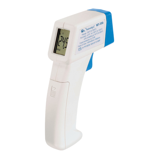
- Page 1 TERMÔMETRO INFRAVERMELHO INFRARED THERMOMETER MT-350 MANUAL DE INSTRUÇÕES INSTRUCTION MANUAL...
-
Page 2: Table Of Contents
ÍNDICE 1. INTRODUÇÃO ..........02 2. INFORMAÇÕES DE SEGURANÇA ....02 3. ESPECIFICAÇÕES .......... 03 3.1 Especificações Gerais ......03 3.2 Especificações do Laser ......04 3.3 Especificações Elétricas ......04 4. DESCRIÇÃO DO INSTRUMENTO ....05 5. OPERAÇÃO ............. 06 5.1 Modo de Operação ........ -
Page 3: Introdução
1. INTRODUÇÃO Este instrumento é um termômetro digital infra- vermelho de 3 1/2 dígitos, com mira laser, portátil, fácil de utilizar e desenhado para ser operado com apenas uma só mão. O medidor possui display LCD iluminado, tampa protetora contra poeira, função Hold e desligamento automático (10 segundos aprox.) após soltar o gatilho para prolongar a vida útil da bateria. -
Page 4: Especificações
• O símbolo no instrumento indica que o usuário deve referir-se a explicação no manual. 3. ESPECIFICAÇÕES 3.1 Especificações Gerais • Display: Cristal líquido de 3 1/2 dígitos (LCD) com leitura máxima de 1999. • Indicação de Bateria Fraca: O “ “... -
Page 5: Especificações Do Laser
3.2 Especificações do Laser • Classificação de Segurança do Laser: Classe II. • Comprimento de Onda: Vermelho (630 ~ 670nm). • Distância de Operação: 2 a 50 pés (0.6 ~ 15m). • Potência de Saída: < 1mW (Classe II). 3.3 Especificações Elétricas •... -
Page 6: Descrição Do Instrumento
4. DESCRIÇÃO DO INSTRUMENTO Fig. 1 1. Display de Cristal Líquido. 2. Gatilho. 3. Sensor Infravermelho e Mira Laser. 4. Compartimento de Bateria. 5. Chave de Seleção °C / °F (dentro do compartimento de bateria). -
Page 7: Operação
5. OPERAÇÃO Gatilho O laser e a iluminação do display funcionam ao mesmo tempo quando o aparelho é ligado. Pressione o gatilho para ligar o medidor se ele estiver desligado. Se o gatilho é solto, o valor é congelado e o símbolo HOLD aparece. -
Page 8: Localizar O Ponto De Maior Temperatura
4. Verifique a figura referente ao diâmetro com relação a distância e o ponto do laser no objeto cuja temperatura deverá ser medida. 5. Recoloque a tampa protetora para prolongar a vida do sensor e prevenir acidentes pelo uso indevido do laser. -
Page 9: Campo De Visão
5.3 Campo de Medição Certifique-se de que o objeto é maior do que a área de medição do termômetro. Quanto menor for o objeto, mais próximo o termômetro deverá estar. Quando a precisão for crítica, certifique-se de que o objeto é duas vezes ou mais a área de medição. A medida que a distância do termômetro ao objeto aumenta, a área de medição aumenta propor- cionalmente. - Page 10 temperatura da superfície do vidro. • Vapor, pó, fumaça, etc. podem prejudicar a precisão das medições, obstruindo o campo de visão do instrumento. ADVERTÊNCIA • Nunca use o instrumento perto de qualquer dispositivo que possa gerar radiação eletro- magnética ou perto de uma carga eletrostática, isto pode causar erro.
-
Page 11: Considerações Da Medida
• Nunca coloque o instrumento sobre ou ao redor de objetos quentes (70°C / 158°F), pois isto pode causar danos ao gabinete do instrumento. • Se o instrumento é exposto à mudanças significativas de temperatura ambiente (frio para quente ou quente para frio), permita que o instrumento estabilize a temperatura por 20 minutos antes de executar a medição. -
Page 12: Estrutura Do Termômetro De Emissão
facilmente através do ar enquanto é facilmente absorvida por matérias sólidas. Com um termômetro de emissão que opera detectando radiação infravermelho é possível uma medição precisa. Independente da temperatura do ar ou da distância de medição. 6.3 Estrutura do Termômetro de Emissão A radiação que foi emitida pelo objeto é... -
Page 13: Cuidados Especiais
6.5 Cuidados Especiais • Se a superfície a ser medida estiver coberta por gelo ou outro material, limpe-o para expor a superfície. • Se a superfície a ser medida é altamente reflexiva, aplique uma fita ou tinta preta na superfície. •... -
Page 14: Acessórios
Tijolo (vermelho) 0.93 a 0.96 Pano (preto) 0.98 Pele Humana 0.98 Espuma 0.75 a 0.80 Carvão Vegetal (pó) 0.96 Verniz 0.80 a 0.95 Verniz (fosco) 0.97 Borracha (preta) 0.94 Plástico 0.85 a 0.95 Madeira 0.90 Papel 0.70 a 0.94 Óxido de Cromo 0.81 Óxido de Cobre 0.78... -
Page 15: Manutenção
8. MANUTENÇÃO 8.1 Troca de Bateria O instrumento é alimentado por uma bateria de 9V (NEDA 1604, IEC 6F22). O símbolo aparece no display LCD quando a troca da bateria é necessária. Para substituir a bateria, siga o procedimento descrito abaixo: 1- Retire a tampa do compartimento da bateria cuidadosamente, escorregando para baixo a tampa do medidor. -
Page 16: Garantia
B) Os serviços de reparação serão efetuados somente no departamento de assistência técnica por nós autorizado. C) Aquisição for feita em um posto de venda credenciado da Minipa. 3- A garantia perde a validade nos seguintes casos: A) Mau uso, alterado, negligenciado ou danificado por acidente ou condições anormais de operação ou manuseio. - Page 17 - Correio: Envie uma cópia do certificado de garantia devidamente pre- enchido pelo correio para o endereço. Minipa Indústria e Comércio Ltda. At: Serviço de Atendimento ao Cliente Alameda dos Tupinás, 33 - Planalto Paulista CEP: 04069-000 - São Paulo - SP - Fax: Envie uma cópia do certificado de garantia devidamente pre-...
- Page 18 TABLE OF CONTENTS 1. INTRODUCTION ..........18 2. SAFETY INFORMATION ........ 18 3. SPECIFICATION ..........19 3.1 General Specification ....... 19 3.2 Laser Specification ........20 3.3 Electrical Specification ......20 4. INSTRUMENT DESCRIPTION ......21 5. OPERATION ............ 22 5.1 Operation Mode ........
-
Page 19: Introduction
1. INTRODUCTION This instrument is a portable easy to use 3 1/2 digits, compact-sized digital infrared thermometer with la- ser sighing, designed for simple one hand operation. Meter comes with backlight display, sensor cover, Auto Hold function and auto power down (10 sec- onds approx.) after releasing trigger to extend bat- tery life. -
Page 20: Specification
• The symbol identifies hazardous conditions, where the user must be referred to manual. 3. SPECIFICATION 3.1 General Specification • Display: 3 1/2 digit liquid crystal display (LCD) with maximum reading of 1999. • Low Battery Indication: The “ “ indicator is displayed when the battery voltage drops below the operating level. -
Page 21: Laser Specification
3.2 Laser Specification • Laser Safety Classification: Class II. • Wavelength: Red (630 ~ 670nm). • Operating Distance: 2 to 50 feet (0.6 ~ 15m). • Output Power: < 1mW (Class II). 3.3 Electrical Specification • Temperature Range: -30°C ~ 550°C / 22°F ~ 1022°F. •... -
Page 22: Instrument Description
4. INSTRUMENT DESCRIPTION Fig. 1 1. Liquid Crystal Display. 2. Trigger. 3. Infrared Sensor and Laser Sighting. 4. Battery Compartment. 5. °C / °F Selection Switch (inside battery compartment). -
Page 23: Operation
5. OPERATION Trigger The laser and backlight function work at the same time wen the power on. Pull the trigger to turn on the meter when power off. If the trigger release the value will be held and HOLD displayed. Auto Power-Off Function It will auto power off for about 10 seconds. -
Page 24: Highest Temperature Location
4. Referring to the spot size figure, aim the laser beam at the object whose temperature is to be measured. 5. Pull the cap on to extend life of the sensor and to avoid danger caused by wrong way to use laser. REMARK: Although the field of measurement (or field of view) and the spot almost coincide, actu- ally the field of measurement corresponds to the... -
Page 25: Field Of View
5.3 Field of View Make sure that the object to be measured is larger than the unit’s spot size. As smaller the object, closer the meter should be to it. When the accuracy is critical, make sure the object is at least twice larger than the spot size. As the distance of the meter to the object increase, the spot size increase proportionally. - Page 26 the surface temperature of the glass instead. • Steam, dust, smoke, etc. can impair accurate mea- surement by obstructing the unit’s field of view. WARNING • Do not use the unit near any device which gener- ates strong electromagnetic radiation or near a static electrical charge, as these may cause er- rors.
-
Page 27: Measurement Considerations
• Do not place the meter on or around hot objects (70°C / 158°F). It may cause damage to the case. • If the meter is exposed to significant changes in ambient temperature (hot to cold or cold to hot). Allow 20 minutes for temperature stabilization, be- fore taking measurement. -
Page 28: Structure Of Emission Thermometer
With an emission thermometer which operates by detecting infrared radiation accurate measurement is possible, irrespective of the air temperature or the measurement distance. 6.3 Structure of Emission Thermometer Infrared radiation which has been emitted from the object is focused upon an infrared radiation sensor, via an optical system. -
Page 29: Specials Attentions
6.5 Specials Attentions • If the surface to the measured is covered by frost or other material, clean it to expose the surface. • If the surface to be measured is highly reflective, apply masking tape or finish black paint to the sur- face. -
Page 30: Accessories
Brick (red) 0.93 to 0.96 Cloth (black) 0.98 Human Skin 0.98 Lather 0.75 to 0.80 Charcoal (powder) 0.96 Lacquer 0.80 to 0.95 Lacquer (mat) 0.97 Rubber (black) 0.94 Plastic 0.85 to 0.95 Timber 0.90 Paper 0.70 to 0.94 Chromium Oxides 0.81 Copper Oxides 0.78... -
Page 31: Maintenance
8. MAINTENANCE 8.1 Battery Replacement This instrument is supplied with 9V (NEDA 1604, IEC 6F22). The symbol appears in LCD display when the replacement is necessary. To replace the battery, follow the procedure listed below: 1- Pull off battery cover, by gently sliding it towards the bottom of the meter. -
Page 32: Warranty
5- For instrument with software, Minipa assumes responsibility that the software will operate in accordance with its functional specifi- cations for 90 days. Minipa will not guarantee that the software will be error free or operate without interruption. 6- Minipa assumes no risk for damage in transit or transportation costs. - Page 33 Scanning this form and attach to your e-mail. Please send to sac@minipa.com.br. - Site: Register the warranty certificate by http://www.minipa.com.br/sac. IMPORTANT The warranty conditions and limitations will be valid only to the certificates correctly registered. In case the purchaser did not register, a sales receipt showing the date of purchase will be required.
- Page 34 Minipa Indústria e Comércio Ltda. Al. dos Tupinás, 33 - Planalto Paulista - São Paulo - CEP: 04069-000 CGC: 43.743.749/0001-31 Site: http://www.minipa.com.br...
Need help?
Do you have a question about the MT-350 and is the answer not in the manual?
Questions and answers