Table of Contents
Advertisement
Available languages
Available languages
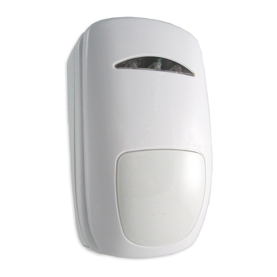
Diagram 1 – Unit Description
Diagramma 1 – Descrizione Dispositivo
3
2
1
Ensure that the
1.
Off the Wall Tamper Cup
wiring loom does
2.
Off the Wall Tamper Screw Positions
not cover the off
3.
Terminal Block (see Diagram 2)
the wall tamper
4.
Cable Knockout Positions
cup
5.
Cable Tie Point for Strain Relief (Base Plastic)
6.
End Of Line Selection (Underside of board)
7.
Microwave Range Control
8.
PIR Detector (do not touch)
9.
Cover Screw (loosen only – do not remove)
Accertarsi che il
cavo non copra
1.
Posizione molla Antirimozione
la posizione del
2.
Posizione viti antirimozione
tamper
3.
Morsettiera (vedi Diagramma 2)
rimozione
4.
Posizione fori passaggio cavi
5.
Punto di ancoraggio per fascette (sulla base plastica)
6.
Selezione EOL (sotto la scheda)
7.
Regolazione portata microonda
8.
Sensore PIR (non toccare)
9.
Vite coperchio (allentare – non rimuovere)
Diagram 2 – Terminal block
EOL2 is the 2 resistor network wiring (3 and 6)
EOL3 is the 3 resistor network wiring (6 and 10)
Diagramma 2 – Morsettiera
4
5
NC
NC
+12
ALLARME
MANOM
EOL2 è il tipo di connessione con 2 resistenze (tra 3 e 6)
EOL3 è il tipo di connessione con 3 resistenze (tra 6 e 10)
6
Diagram 3 – Cover Release Slot
Diagramma 3 – Apertura del coperchio
The cover on this detector is held in
place with a screw and a clip. To release
the cover, loosen the screw and insert a
7
flat blade screwdriver into the slot and
twist. To refit the cover, press the two
halves together (there will be an audible
click) and then tighten the screw.
8
Il coperchio è tenuto chiuso con una vite
e un fermo a clip. Per aprire il coperchio, allentare la vite e tramite un
cacciavite a lama , sganciare la clip.
9
Per chiudere il DT15AM premere il coperchio sulla base, si udirà un
clic e serrare la vite.
Diagram 4 – Coverage Diagrams
Diagramma 4 – Diagrammi di copertura
Volumetric Plan View
Copertura volumetrica vista laterale 15mt
Numero di raggi : 15 su 3 livelli + 1 anti-avvicinamento
10
8
anti
6
4
2
0
2
4
6
8
10
0
2
4
6
8
10
Volumetric Side View
Copertura volumetrica vista laterale 15mt
Numero di raggi : 15 su 3 livelli + 1 anti-avvicinamento
2.3
0
2
4
6
8
10
English
DT15-AM is a dual technology detector with acitve IR anti-masking. It
employs advanced digital processing algorithms to provide superior
catch performance while not compromising on false alarm immunity.
Features such as Microwave Day Disable and Anti-Stealth compliment
an already full feature set.
Use in EN50131 Compliant Systems
DT15-AM meets the requirements of TS50131-2-4:2004, Grade 3,
NC
Class II with SW4 and SW5 ON and the other switches OFF. This
AUX
applies when mounted on a vertical surface between 2.1 and 2.5m
high with the microwave set to max. Changing these settings may
affect approval compliance.
Declaration of Conformity:
Guardall Ltd, declares that DT15 AM/100 is approved for use in UK,
Eire and Italy and is in compliance with the essential requirements
and other relevant provisions of EU Directive 1999/5/EC.
Intended use: Within a building as an intruder detection device.
Safety Information: The power feed must be fused at 5A or less.
1. Technical Specification
Voltage
12V (9V to 16Vdc)
Current
Quiescent – 15mA @ 12V
Max – 23mA @ 12V (LED ON)
Alarm, Aux &
Normally closed (NC). Rated at 24V dc, 50mA
Tamper
Test Input
Positive supply to enable LED and control
Remote Self Test
Control Input
Positive supply for system Set. Otherwise
Unset
Microwave
50% to 100% of range via potentiometer (turn
range
fully clockwise for 100%)
See datasheet for full information
2. Installation Location
The recommended mounting height is 2.3m and the coverage is
shown in diagram 4. The unit can be mounted between 2.1m and
2.5m without adjustment, when mounted on a vertical surface. Ensure
the detector's field of view is not obscured.
Please refer to the Installation Guidance Notes available on our
website or call the Technical Hotline for further information.
Select Switch 1 to ON.
The yellow LED displays PIR activity. In rooms smaller than 10m,
select switch 7 ON.
The green LED displays microwave activity. Range is adjusted via the
microwave range control (Diagram 1 Item 7)
The Red LED displays unit alarms.
Walk test the area checking that alarms are indicated at the control
panel.
4. Operating Features
12
14
16
No.
Function
1
LED Enable
2
Pulse Count
3
UW Day Disable
4
AM/Faults O/P
5
AM Sensitivity
6
Anti-Stealth
7
PIR Range
12
14
16
8
AM Disable
SW1: LED Enable
See LED indications (section 9 & 10)
SW2: Pulse Count
In harsh environments select Switch 2 ON
SW3: Microwave Day Disable
For microwave permanently active select Switch 3 OFF
For microwave disabled when system Unset select Switch 3 ON
SW4: Anti-mask / Fault Output
SW4
Faults Signalled On
ON
Aux Relay +
LED (if enabled)
OFF
LED
To reset a mask: Remove the mask, wait 30 secs, generate an alarm.
SW5: Anti-Mask Sensitivity
For EN Grade 3 installations select Switch 5 ON.
SW6: Anti-Stealth
Only in high security applications select Switch 6 ON
SW7: PIR Range
In rooms smaller than 10m, select Switch 7 ON
SW8: Anti-Mask disable
To disable the Anti-Mask select Switch 8 ON
This feature detects an attempt to blind the detector when the system
is unset (e.g. during the day). Both active infrared, and microwave
systems are used to detect if objects are placed in its field of view or if
the detector has been sprayed with paint etc. thereby allowing an
intruder to enter the premises at a later date without being detected.
The Anti-Mask system will only operate/calibrate correctly when the
cover is fitted. Following installation a full Anti-Mask calibration should
be carried out using one of the following methods:
Change the position of Switch 4 and return it
Stay clear (1 meter) of the unit for 2 minutes while the Anti-Mask is
calibrating.
Anti-Stealth is a new highly intelligent feature for dual-tech detectors
which analyses microwave and PIR activity in a room and is able to
detect intruders with very low temperature differentials to the
environment.
7. Remote Self Test (RST)
With Switch 4 ON and Switch 1 OFF, an RST is generated when the
TEST Input is taken high to low. The alarm output will signal a
successful RST. A failure will generate a fault condition. This is only
reset by a successful RST.
8. Alarm Memory
System Set (see Control Input - Technical Specification section 1)
Should an alarm occur the alarm will be memorised.
System Unset and SW1 OFF
TEST Input Low
TEST Input High
Memory reset occurs the next time the system is SET.
1 2 3 4 5 6 7 8
Mask Signalled On
Alarm + Aux Relays +
LED (if enabled)
Aux Relay + LED
Applying power to the unit
OR
to the original position in 3 seconds
The LED will remain ON (if an alarm
is memorised)
The LED displays normally without
losing alarm memory
Advertisement
Table of Contents

Summary of Contents for Gaurdall DT15-AM
- Page 1 See LED indications (section 9 & 10) Diagramma 1 – Descrizione Dispositivo SW2: Pulse Count DT15-AM is a dual technology detector with acitve IR anti-masking. It In harsh environments select Switch 2 ON employs advanced digital processing algorithms to provide superior SW3: Microwave Day Disable catch performance while not compromising on false alarm immunity.
-
Page 2: Led Indications
9. LED Mode Setting Italiano 9. Indicazione Led System Set No LED indications DT15-AM è un sensore a doppia tecnologia con IR attivo anti Sistema inserito nessuna indicazione sui LED System Unset Funzione mascheramento. Utilizza un algoritmo digitale avanzato per fornire Sistema disinserito The following table applies.
Need help?
Do you have a question about the DT15-AM and is the answer not in the manual?
Questions and answers