Table of Contents
Advertisement
Quick Links
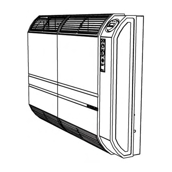
GAS FIRED WALL FURNACES MODELS 5001/8001 - 5002/8002
INSTALLATION INSTRUCTIONS AND OWNER'S MANUAL
WARNING: If the information in this
manual is not followed exactly, a fire or
explosion may result causing property
damage, personal injury or loss of life.
– Do not store or use gasoline or other
flammable vapors and liquid in the
vicinity of this or any other appliance.
– WHAT TO DO IF YOU SMELL GAS
• Open windows
• Do not try to light any appliance
• Do not touch any electrical switch;
do not use any phone in your
building.
• Immediately call your gas supplier
from a neighbor's phone. Follow the
gas supplier's instructions.
• If you cannot reach your gas
supplier, call the fire department.
– Installation and service must be
performed by a qualified installer, service
agency or the gas supplier.
WARNING: If not installed, operated
and maintained in accordance with
the manufacturer's instructions, this
product could expose you to
substances in fuel or from fuel
combustion which can cause death or
serious illness and which are known
to cause cancer, birth defects or other
reproductive harm.
DIRECT VENT WALL FURNACE
MODELS
5001, 5002, 8001, 8002
Advertisement
Table of Contents

Summary of Contents for Eurotherm 5001
- Page 1 GAS FIRED WALL FURNACES MODELS 5001/8001 - 5002/8002 INSTALLATION INSTRUCTIONS AND OWNER’S MANUAL WARNING: If not installed, operated WARNING: If the information in this and maintained in accordance with manual is not followed exactly, a fire or the manufacturer’s instructions, this...
- Page 2 5001/5002 – 8001/8002 Installation Instructions and Owner’s Manual Edition: 06/2006 Codice: D-LBR420 This manual was written and printed by Robur S.p.A.; part or total reproduction of this manual is prohibited. The original is filed in Robur S.p.A. Any use of this manual other than personal consultation must be previously authorized by Robur S.p.A.
-
Page 3: Table Of Contents
GAS SUPPLY ............................16 ELECTRICAL WIRING DIAGRAMS......................18 SECTION 3 OPERATING INSTRUCTIONS ..............21 OPERATING INSTRUCTIONS FOR MODELS 5001 and 8001 ............. 21 OPERATING INSTRUCTIONS FOR MODELS 5002 and 8002 ............. 22 SECTION 4 SERVICING....................25 CHECKING AND ADJUSTING THE GAS MANIFOLD PRESSURE ............25 CHECKING, REMOVING AND REASSEMBLING OF THE VENT –... - Page 4 5001/5002 – 8001/8002 Installation Instructions and Owner’s Manual Ed. 06/2006...
-
Page 5: Section 1 General Information And Technical Data
Installer should show owner how to start and MODELS DESCRIPTION The 5001, 8001, 5002, 8002 units are gas heaters, an independent heating product with an isolated combustion chamber and forced draught. It can operate either with natural gas and liquid propane gas. -
Page 6: General Warnings
5001/5002 – 8001/8002 Installation Instructions and Owner’s Manual Models 5002 and 8002 grant a higher comfort thanks to an air humidifier placed on the left hand side of the unit. Additionally, models 5002 and 8002 can also operate in summer time (the fan can work while the burner is off). - Page 7 General Information and Technical Data SAFETY INFORMATION FOR USERS OF LP–GAS Propane (LP–Gas) is a flammable gas which can the members of your household. Someday when there cause fires and explosions. In its natural state, may not be a minute to lose, everyone’s safety will propane is odorless and colorless.
-
Page 8: Technical Data
5001/5002 – 8001/8002 Installation Instructions and Owner’s Manual TECHNICAL DATA 5001 5002 8001 8002 4.25 6.98 OUTPUT HEATING CAPACITY kBTU/hr 14.514 23.817 5.19 8.50 INPUT RATING (HI input) kBTU/hr 17.700 29.000 — 3.84 — 5.89 MINIMUM INPUT RATING (LO input) kBTU/hr —... - Page 9 General Information and Technical Data 5001 5002 8001 8002 mbar NATURAL W.C. mbar 26.4 26.5 10.6 10.6 W.C. mbar — — NATURAL — — W.C. mbar — 16.3 — 16.2 — — W.C. NATURAL 17.8 30.1 11.6 — — NATURAL —...
- Page 10 Gas Pipe Capacities (Up to 14" W.C. Gas Pressure through Schedule 40 Pipe) Cubic Feet per Hour with Pressure Drop of 0.3" W.C. Natural Gas - Specific Gravity - 0.60 Propane Gas - Specific Gravity - 1.50 Pipe Diameter Length of Pipe 1/2"...
-
Page 11: Section 2 Installation
Installation SECTION 2 INSTALLATION Installation should be done by a QUALIFIED SERVICE PERSON. The furnace is to be located on an outside wall. WALL INSTALLATION Minimum clearances from combustible and the air intake shall be located at least 12 in. construction: (300 mm) above grade. - Page 12 5001/5002 – 8001/8002 Installation Instructions and Owner’s Manual 1 = fixed closed 2 = openable V = vent terminal A = air supply A. clearance above grade, veranda, porch, deck, clearance to service regulator vent outlet (6 feet or balcony (12 inches (30 cm) minimum) (1.8 m) minimum)
-
Page 13: Outside Location For Vent Terminal
care not to damage the paper template. This is 4. Drill the fi xing holes A (5 holes for 5001/5002, 8 care not to damage the paper template. This is ... - Page 14 NOTE: Adhesive gasket must be placed Bracket Bracket between unit and flanged lip of air inlet pipe and wall bracket. If air inlet pipe is placed Gasket Gasket through the gasket and then attached to the...
- Page 15 Fix the unit to the matching hooks A, with a light pressure against the wall (see Figure 10. FOR 5001/5002 ONLY: install the unit to 9). Install the heating body of the unit to the the wall leaning the bottom edge of panel C...
- Page 16 (see see Figure 10 on page 15). - Positioning of flue exhaust pipe (all models). Figure 7 FOR 5001/5002 FOR 5001/5002 ONLY ONLY - Hanging of the unit to the supporting bracket and matching hooks (for 5001/5002 only) Figure 8 Ed. 06/2006...
- Page 17 Installation FOR 8001/8002 ONLY - Hanging of the unit to the supporting bracket and matching hooks (for 8001/8002 only). Figure 9 Figure 10 - Installation of the vent cap (all models). Ed. 06/2006...
-
Page 18: Gas Supply
5001/5002 – 8001/8002 Installation Instructions and Owner’s Manual GAS SUPPLY Check local codes requirements, test gauge connection, is provided on the especially for the size and type of gas supply gas valve (see A in Figure 11, page 17). line required. On Natural gas lines less than 15”... - Page 19 SCREW FOR LO PRESSURE ADJUSTMENT (HI – LO ELECTRIC CLAMP CONNECTION OPERATOR) ELECTRIC CABLE INLET ELECTRIC CLAMP CONNECTION HOLE FOR GAS SUPPLY INLET ELECTRIC CABLE INLET HOLE FOR GAS SUPPLY INLET FLAME VIEW Figure 11 - Valve manifold - 5001/8001: LEFT; 5002/8002: RIGHT. Ed. 06/2006...
-
Page 20: Electrical Wiring Diagrams
5001/5002 – 8001/8002 Installation Instructions and Owner’s Manual ELECTRICAL WIRING DIAGRAMS Here below the wiring diagrams key for all models (the diagrams follow) EV, EV1 GAS VALVE 1 (SAFETY SHUTTER) VANNE GAS 1 (SECURITE’) HI-LO FLAME OPERATOR (*) OPERATEUR HAUTE-BASSE FLAMME (*) FAN MOTOR (n. - Page 21 Installation 5002 WIRING DIAGRAM Figure 13 - 5002 WIRING DIAGRAM 8001 WIRING DIAGRAM Figure 14 - 8001 WIRING DIAGRAM Ed. 06/2006...
- Page 22 5001/5002 – 8001/8002 Installation Instructions and Owner’s Manual 8002 WIRING DIAGRAM Figure 15 - 8002 WIRING DIAGRAM Ed. 06/2006...
-
Page 23: Section 3 Operating Instructions
OPERATING INSTRUCTIONS Before operating the furnace, read carefully all warnings and safety information on pages 4 and 5 of this manual. OPERATING INSTRUCTIONS FOR MODELS 5001 and 8001 FOR YOUR SAFETY READ BEFORE OPERATING WARNING: If you do not follow these instructions exactly, a fire or explosion may result causing property damage, personal injury or loss of life. -
Page 24: Operating Instructions For Models 5002 And 8002
5001/5002 – 8001/8002 Installation Instructions and Owner’s Manual OPERATING INSTRUCTIONS FOR MODELS 5002 and 8002 FOR YOUR SAFETY READ BEFORE OPERATING WARNING: If you do not follow these instructions exactly, a fire or explosion may result causing property damage, personal injury or loss of life. - Page 25 B. Turn the thermostat knob to zero setting, then turn it back to comfort setting after some seconds; C. Press the reset button once (5001/8001 models), or press the SUMMER/WINTER button to SUMMER (button down) for some seconds, then push it back (button up) to WINTER position (5002/8002 models).
- Page 26 5001/5002 – 8001/8002 Installation Instructions and Owner’s Manual USING ALL THE FEATURES OF YOUR 5002/8002 HEATER GREEN LAMP: it is alight when the flame is ON RED LAMP: in case the flame disappears the gas flow will be shut off and the red lamp will alight instead of the green one. The unit is locked–out.
-
Page 27: Section 4 Servicing
LO operator adjustment) until end of stroke, them independently from each other. by turning it clockwise. Do not force. 5001/8001: adjust the manifold pressure by 3. Adjust the HI pressure by turning the screw rotating the regulation screw clockwise to... -
Page 28: Lubrication Of Moving Parts
5001/5002 – 8001/8002 Installation Instructions and Owner’s Manual 5. Reinstall the flue pipe from outside. Do not 6. Reinstall the vent cap on the flue pipe. Do use glue or sealants: the gasket ensures not use glue or sealants. Tighten the three complete seal of the connection. -
Page 29: Section 5 Programmable Timer
Programmable Timer SECTION 5 PROGRAMMABLE TIMER The programmable timer (Figure 16 below) allows precise operating and timing control. The programmable timer is supplied as a standard with 5002 and 8002 units. OVERVIEW The programmable timer has the following characteristics: Long life lithium battery •... -
Page 30: Setting And Adjustment
5001/5002 – 8001/8002 Installation Instructions and Owner’s Manual SETTING AND ADJUSTMENT INITIAL CONDITIONS 1 2 3 4 5 6 7 A. Make sure that the B selector is in RUN position. After pressing the 0:00 reset button R, the display starts flashing. - Page 31 Programmable Timer TIME SETTING Example: Set Wednesday, 15.16 hours. location. A. The selector B is to be moved to 1 2 3 4 5 6 7 B. Set the day of the week. Press the day key 1..7, the triangular 0:00 shaped indicator proceedes one unit at a time.
- Page 32 5001/5002 – 8001/8002 Installation Instructions and Owner’s Manual (Sat and Sun) • F. When all setting operations have been carried out, check and ensure that the different programs do not contrast many times one with the others in order to avoid undesired operations. You can check on the display the different settings (programmes) by simply pressing button many times.
- Page 33 5001/5002 – 8001/8002 Installation Instructions and Owner’s Manual Ed. 06/2006...
- Page 34 Programmable Timer 100 Quaker Lane • Malvern, PA 19355 Phone: 877-930-2739 Fax: 610-240-4906 www.eurothermsystems.com Ed. 06/2006...
Need help?
Do you have a question about the 5001 and is the answer not in the manual?
Questions and answers