Table of Contents
Advertisement
Advertisement
Table of Contents

Summary of Contents for FlyTech POS 8000
- Page 1 User Manual Version 1.2 May 2012 Point-of-Sale Hardware System...
- Page 2 Copyright 2012 All Rights Reserved Manual Version 1.2 Part Number:3LMPP8000112 The information contained in this document is subject to change without notice. We make no warranty of any kind with regard to this material, including, but not limited to, the implied warranties of merchantability and fitness for a particular purpose.
-
Page 3: Important Safety Instructions
Safety IMPORTANT SAFETY INSTRUCTIONS To disconnect the machine from the electrical Power Supply, turn off the power switch and remove the power cord plug from the wall socket. The wall socket must be easily accessible and in close proximity to the machine. Read these instructions carefully. - Page 4 CAUTION ON LITHIUM BATTERIES There is a danger of explosion if the battery is replaced incorrectly. Replace only with the same or equivalent type recommended by the manufacturer. Discard used batteries according to the manufacturer’s instructions. Battery Caution Risk of explosion if battery is replaced by an incorrectly type. Dispose of used battery according to the local disposal instructions.
- Page 5 The crossed dustbin symbol on the device means that it should not be disposed of with other household wastes at the end of its working life. Instead, the device should be taken to the waste collection centers for activation of the treatment, collection, recycling and disposal procedure.
- Page 6 Revision History Changes to the original user manual are listed below: Revision Date Description V 1.0 November, 2011 Initial release V 1.1 December, 2011 C46 M/B updated to v1.3 C56 M/B and C65M/B V1.2 May, 2012 added...
-
Page 7: Table Of Contents
Table Contents 1 Item Checklist ............1 Standard Items................1 Optional Items ................2 2 System View............3 Front View ..................3 Side View ..................4 I/O View................... 4 3 System Assembly & Disassembly ......8 Remove the Top Cover ..............8 Replace the HD ................9 Remove the RAM Module ............10 4 Peripheral Installation ........ - Page 8 This page is intentionally left blank...
-
Page 9: Item Checklist
Item Checklist Take the unit out of the carton. Remove the unit from the carton by holding it by the foam inserts. The following contents should be found in the carton: 1-1 Standard Items a. System b. COM cable (x1) c. -
Page 10: Optional Items
1-2 Optional Items a. Wall Mount Kits (x2) -
Page 11: System View
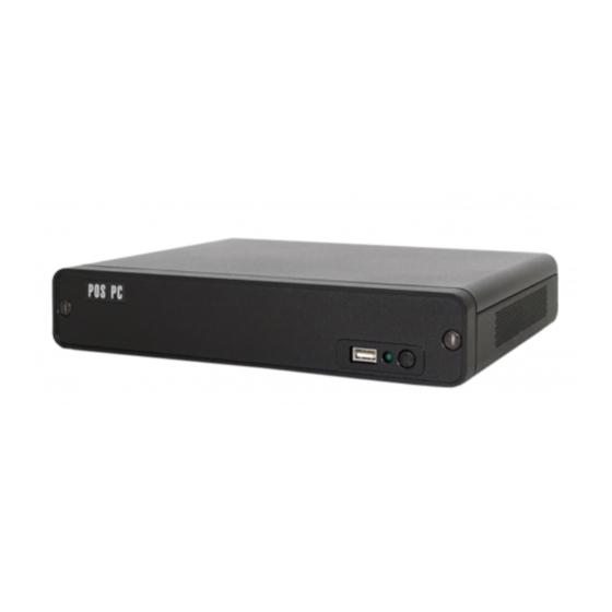
System View 2-1 Front View C46/C56 Motherboard Number Description Front cover Slotted screw C65 Motherboard Number Description Front cover Slotted screw Indicator LED (Green) Power button... -
Page 12: Side View
2-2 Side View Number Description Ventilation hole 2-3 I/O View C46 Motherboard Number Description USB x2 Cash drawer port USB x 4 COM1~4 (from left to right) DC IN 19V Power button Cable clamp Kensington lock Indicator LED (Green) Note: The maximum current that can be drawn from each COM port is 500 mA. - Page 13 C56 Motherboard Number Description Parallel Cash drawer port USB x4 COM1~4 (from left to right) DC IN 19V Power button Antenna hole PS/2 USB x2 Indicator LED (Green) Cable clamp Kensington lock Note: The maximum current that can be drawn from each COM port is 500 mA.
- Page 14 C65 Motherboard Number Description DC IN 19V PS/2 Cash drawer port COM1~4 (from left to right) USB x4 Line-out Power button Antenna hole Cable clamp DVI-D Parallel USB x2 Kensington lock Note: The maximum current that can be drawn from each COM port is 500 mA.
- Page 15 C65 Motherboard (with power USB) Number Description DC IN 19V PS/2 Cash drawer port COM1~4 (from left to right) USB x4 Line-out Power button Antenna hole Cable clamp DVI-D Parallel DC OUT 24V Power USB x3 USB x2 Kensington lock Note: The maximum current that can be drawn from each COM port is 500 mA.
-
Page 16: System Assembly & Disassembly
System Assembly & Disassembly 3-1 Remove the Top Cover Remove the screws (x2) to release the front cover. Remove the screws (x2). Slide the top cover outwards. -
Page 17: Replace The Hd
3-2 Replace the HD C46 Motherboard To replace the HD, please remove the top cover as described in Chapter 3-1 Remove the screw (x1). Pull the HD away from the system. C56 Motherboard To replace the HD, please remove the top cover as described in Chapter 3-1 Remove the screw (x1). -
Page 18: Remove The Ram Module
C65 Motherboard To replace the HD, please remove the top cover as described in Chapter 3-1 Remove the screws (x3) to separate Remove the screws (4) and replace the the HD module from the system. 3-3 Remove the RAM Module C46 Motherboard To replace the RAM, please remove the top cover as described in Chapter 3-1 Flip the ejector clips outwards to... - Page 19 C56 Motherboard To replace the RAM, please remove the top cover as described in Chapter 3-1 Flip the ejector clips outwards to remove To install a RAM module, slide the the memory module from the memory memory module into the memory slot slot.
-
Page 20: Peripheral Installation
Peripheral Installation 4-1 Wall Mounting Kits Installation Turn over the system and fasten the screws (x4) as shown in the picture. -
Page 21: Cash Drawer Installation
4-2 Cash Drawer Installation You can install a cash drawer through the cash drawer port. Please verify the pin assignment before installation. Cash Drawer Pin Assignment Signal DOUT bit0 DIN bit0 12V / 19V DOUT bit1 Cash Drawer Controller Register The Cash Drawer Controller use one I/O addresses to control the Cash Drawer. - Page 22 Bit 7: Reserved Bit 6: Cash Drawer “DIN bit0” pin input status. = 1: the Cash Drawer closed or no Cash Drawer = 0: the Cash Drawer opened Bit 5: Reserved Bit 4: Reserved Bit 3: Cash Drawer “DOUT bit1” pin output control. = 1: Opening the Cash Drawer = 0: Allow close the Cash Drawer Bit 2: Cash Drawer “DOUT bit0”...
-
Page 23: Specification
Specification C46/C56 Motherboard Model Name POS 8000 POS 8000 Motherboard C46M C46H Intel Pineview D525 processors 1.8G, L2 Intel CedarView D2550 processor 1.86GHz 1MB 1M, Dual-Core, 13W Cache, 32nm, 4 threads, 10W Chipset Intel® ICH8M Intel® NM10 DDR3, SO-DIMM x... - Page 24 Indicator LED (Green) Expansion Power USB module Wireless LAN half-size miniCARD type (PCI-E), 802.11 b/g/n wireless LAN card & antenna Wall Mount Kit Environment EMC & Safety FCC Class A, CE, LVD Operating Temperature C~ 35 C (32 F ~ 95 Storage Temperature C ~ 60 C (-4...
- Page 25 C65 Motherboard Model Name POS 8000 Motherboard C65M C65H Intel Sandy Bridge CPU, LGA 1155-pin, 32nm i5-2390T 2.7G, L2 6M, TDP 35W, Intel Sandy Bridge CPU, LGA 1155-pin, 32nm i3-2120 3.3G, L2 3M, TDP 65W, Pentium G620T 2.2G, L2 3M, 35W Pentium G850 2.9G, L2 3M, 65W...
- Page 26 half-size miniCARD type (PCI-E), 802.11 half-size miniCARD type (PCI-E), 802.11 b/g/n wireless Wireless LAN b/g/n wireless LAN card & antenna LAN card & antenna (Choose either wireless or 2nd LAN) Wall Mount Kit Environment EMC & Safety FCC Class A, CE, LVD Operating Temperature C~ 35 C (32...
-
Page 27: Jumper Settings
Jumper Settings 6-1 C46 Motherboard Layout 6-1-1 Motherboard Layout Version: C46 v1.3... - Page 28 6-1-2 Connectors & Functions Connector Function USB CONN Speaker and MIC CONN HDD Power CONN USB CONN CN12 PS2 Keyboard CONN CN18 Power LED CONN CN22 Power Button CONN CN25 Battery CONN PWR3 DC-JACK CN25 Battery CONN DDR3_A1 DDR3 SO-DIMM1 RJ11_3 Cash Drawer Port RJ45_3...
- Page 29 6-1-3 Jumper Settings Cash Drawer Power Setting Function (1-2) (3-4) ▲19V CRT Power Ctrl Function (1-2) 12V output ▲ Control by BIOS ▲ = Manufacturer Default Setting OPEN SHORT...
- Page 30 COM3 & COM4 Power Setting COM3 and COM4 can be set to provide power to your serial device. The voltage can be set to +5V or 12V by setting jumper JP9 on the motherboard. When enabled, the power is available on pin 10 of the RJ45 serial connector. If you use the serial RJ45 to DB9 adapter cable, the power is on pin 9 of the DB9 connector.
- Page 31 COM Power Setting Function (1-2) (3-4) (5-6) (7-8) ▲COM3 5V COM3 12V COM4 5V ▲COM4 12V ▲ = Manufacturer Default Setting OPEN SHORT...
- Page 32 2nd VGA Power Setting VGA port power must be on through BIOS/Utility for default is “No Power“ Power on the system, and press the <DEL> key when the system is booting up to enter the BIOS Setup utility. Select the Advanced tab Select "Power Configuration COM/VGA Ports"...
-
Page 33: C56 Motherboard
6-2 C56 Motherboard 6-2-1 Motherboard Layout Version: C56 v0.9... - Page 34 6-2-2 Connectors & Functions Connector Function Power LED CONN Speaker & MIC CONN HDD Power CONN CN10 Printer Port CONN CN11/12 USB CONN CN14 PS2 Keyboard CONN CN17 Power Button CONN CN18 TO Front I/O Board PWR1/2 DC-JACK RJ11_1 Cash Drawer Port RJ45_1 LAN Port RJ45_2...
- Page 35 6-2-3 Jumper Settings Cash Drawer Power Setting Function (1-2) (3-4) ▲19V...
- Page 36 COM2/COM3/COM4 Power Setting COM2, COM3 and COM4 can be set to provide power to your serial device. The voltage can be set to +5V or 12V by setting jumper JP9 on the motherboard. When enabled, the power is available on pin 10 of the RJ45 serial connector. If you use the serial RJ45 to DB9 adapter cable, the power is on pin 9 of the DB9 connector.
- Page 37 COM 3 & COM4 Power Setting Function (1-2) (3-4) (5-6) (7-8) ▲COM3 +5V COM3 +12V COM4+ 5V ▲COM4 +12V ▲ = Manufacturer Default Setting OPEN SHORT...
-
Page 38: C65 Motherboard
6-3 C65 Motherboard 6-3-1 Motherboard Layout Version: C65 V1.0... - Page 39 6-3-2 Connectors & Functions Connector Function CN6/CN7 HDD Power CONN Power Button CN10 DVI CONN CN11 To Front I/O Board CN12 USB CONN CN18 Printer CONN CN19 Line Out CN20 Battery CONN DDR3_A1 DDR3 DIMM1 FAN_CPU3 FAN CONN FAN_SYS3 FAN CONN PS2 Port PWR3/4/5 DC-JACK...
- Page 40 6-3-3 Jumper Settings Cash Drawer Power Setting Function (1-2) (3-4) ▲19V/24V System Indicator Function (1-2) (3-4) (5-6) (7-8) ▲Disable Enable ▲ = Manufacturer Default Setting OPEN SHORT...
- Page 41 COM3 & COM4 Power Setting COM3 and COM4 can be set to provide power to your serial device. The voltage can be set to +5V or 12V by setting jumper JP9 on the motherboard. When enabled, the power is available on pin 10 of the RJ45 serial connector. If you use the serial RJ45 to DB9 adapter cable, the power is on pin 9 of the DB9 connector.
- Page 42 COM3~COM4 Power Setting Function (1-2) (3-4) (5-6) (7-8) ▲COM3 5V COM3 12V COM4 5V ▲COM4 12V ▲ = Manufacturer Default Setting OPEN SHORT...
- Page 43 ME update Function JP12 (1-2) ▲Lock Un-Lock ▲ = Manufacturer Default Setting OPEN SHORT...
-
Page 44: Appendix
Appendix Driver Installation: The shipping package includes a Driver CD. You can find every individual driver and utility that enables you to install the drivers in the Driver CD. Please insert the Driver CD into the drive and double click on the “index.htm” to pick up the models.
Need help?
Do you have a question about the POS 8000 and is the answer not in the manual?
Questions and answers