Table of Contents
Advertisement
___________________________________________________________________________
http://waterheatertimer.org/How-to-wire-Intermatic-CA3750.html
Wireless Control System
User Guide
A Step-by-Step Guide for
Planning, Installing, and
Operating a Complete Designer
Wireless Control System
Devices
Mon 12:00 AM
Menu
Back
All ON
Devices
All OFF
Menu
All ON
1
3
5
7
9
Mon 12:00 AM
Back
All OFF
2
4
6
8
10
Advertisement
Table of Contents

Related Manuals for Cooper Aspire RF

Summary of Contents for Cooper Aspire RF
- Page 1 ___________________________________________________________________________ http://waterheatertimer.org/How-to-wire-Intermatic-CA3750.html Wireless Control System Devices Mon 12:00 AM Menu Back Devices All ON All OFF Mon 12:00 AM Menu Back User Guide All OFF A Step-by-Step Guide for All ON Planning, Installing, and Operating a Complete Designer Wireless Control System...
- Page 2 (THIS PAGE INTENTIONALLY LEFT BLANK)
- Page 3 Congratulations! Congratulations on your Purchase of an Wireless Control System! Part of the next generation of convenient, dependable, and user-friendly wireless controls, your new system allows you to create a wireless, two-way network within your family home, condo, or apartment. The network puts you in command of a large number of compatible devices from a single, remote control.
-
Page 4: Table Of Contents
Although previous verions of the User Guide are mostly valid, Version B of the User Guide is best suited for software version 1.1.2. If you have additional questions related to the installation or the operation of your Aspire RF Wireless Control System, please call 1-866-853-4293 or go to cooperwiringdevices.com/AspireRF. - Page 5 Update Secondary Controller Device Information (“Get Name & Locn” feature) ......65 Replace a Failed Device ..................66 Remove a Failed Device ..................67 Utilize Network Discovery ..................68 Ordering Information for Cooper Wiring Devices .............. 69 Glossary ......................71 Warranty ......................73 Devices...
-
Page 6: Safety Information And Fcc Information
• Consult the dealer or an experienced radio/TV technician for help. FCC CAUTION: Any changes or modifications not expressly approved by Cooper Wiring Devices could void the user’s authority to operate the equipment. Cooper Wiring Devices, 203 Cooper Circle, Peachtree City, GA 30269 • 866-853-4293... -
Page 7: Introduction
How the System Works Your ASPIRE RF devices function as both receivers, allowing you to control the loads to which they are attached, and as repeaters, extending and improving signals throughout your home. Rather than depending on line-of-site communications like other technologies, Aspire RF employs Z-Wave technology that creates a “mesh”... -
Page 8: Quick Reference Guide
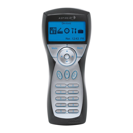
Quick Reference Guide Tabletop Controller Favorite Scene AC adapter plug-in buttons Eight of your favorite scenes can be accessed directly with Back/Cancel an easy one-touch control. Devices button Primary Controller Exit a menu screen and return Callout to the previous menu. Indicates if it is the Mon 12:00 AM primary controller. - Page 9 Quick Reference Guide Handheld Controller Battery Status Indicator Back/Cancel button Appears when battery power is low. Exit a menu screen Devices and return to the Primary Controller previous menu. Callout Mon 12:00 AM Indicates if it is the Arrow pad primary controller.
-
Page 10: Optional Accessories
Optional Accessories Optional Controllers RFWDC – Wall-mount 5-button Scene Controller This controller stores up to five scenes for easy one- touch activation and offers an ALL/OFF button for turning all devices off controlled by this specific Scene Controller. Mounts in any standard single-gang wallbox and requires 120 VAC. -
Page 11: Get Started
Get Started Navigate Menu Screens You can easily navigate through the menu screens on your controllers. Here are some tips to help you become familiar with the system. Note: Data will be lost for current operation if a button is not pressed on the controller within 60 seconds. -
Page 12: Create Custom Names
Get Started Create Custom Names Several features of the wireless system give the option to create custom names. More detailed instructions for each of these features is included in this manual. Here are some tips to introduce you to the process: •... -
Page 13: Set Current Day And Time
Get Started Set Current Day and Time 1. Select the “Day/Time” option from the Settings Settings menu. Press the OK button. Day/Time Panic Replicate Network Discovery 2. Use the up and down arrows to change the Day/Time current day. When finished, press the right arrow to highlight the time. -
Page 14: Install And Control Devices
If you wish to keep the original name, just press the OK Rename Dimmer button. • If the device is a Cooper Wiring product, the Dimmer_12 name is read from the device. The switch, dimmer, or receptacle will automatically be... -
Page 15: Configure A Device
Configure a Device (for compatible products only) All Cooper Wiring devices share common configuration options. You can select your preferred configuration for each device on your system. Note: It is recommended that you be in the same room as the device you are configuring. -
Page 16: Configure Off Delay
Install and Control Devices Configure Off Delay (for compatible products only) This feature gives the user time to leave a room before the light turns off. To activate Off Delay, press and hold the dimmer or switch. The LEDs on the device will flash for the programmed Off Delay time and then go off. - Page 17 Install and Control Devices Configure ALL ON and ALL OFF group (continued) 3. Highlight the specific device you would like to customize. Press the OK button. Devices 1 Device 1 2 Receptacle 4. Use the up and down arrows to scroll and highlight “All Switch All On &...
-
Page 18: Configure Panic On And Off Times
Install and Control Devices Configure Panic On and Off Times (for compatible products only) Panic mode allows the user to trigger a group of devices to turn off and on in a pattern that attracts attention. You can customize the devices you would like to come on as well as the time interval they turn on and off. -
Page 19: Configure Power On State
Install and Control Devices Configure Power On State (for compatible products only) The Power On state defines what state the device powers up into when power resumes after an outage. After an outage, On will turn on the device, Off will leave the device off, and Last will return the device to its state before the outage. -
Page 20: Configure Ramp Time
Install and Control Devices Configure Ramp Time (for dimmers only) (continued) 2. Highlight “Ramp Time” and press the OK Dimmer button to select it. Panic Off Time 00:01 Power On State Last Ramp Time 00:03 Save 3. Using the arrow pad, highlight each number Ramp Time and scroll up or down to select your ramp time up to 4:14 seconds. -
Page 21: Non-Cooper Parameters
Install and Control Devices Non-Cooper Parameters This allows the user to configure the parameters for Cooper devices or non-Cooper devices. Normally this option will NOT be used for Cooper devices since all the configurable items are already listed. Note: Zen-Sys (Z-Wave) requires the configuration parameters to be published. Contact the device manufacturer if these are not available in the documentation with the device. - Page 22 Install and Control Devices Non-Cooper Parameters (continued) When this screen appears, scroll to the Parameter Parameter Number Number you wish to change. Press the OK button. This screen is where you select the value for the Parameter Number 2 Parameter Number you are configuring. The value currently in the device will be highlighted.
-
Page 23: Activate Individual Devices
Install and Control Devices Activate Individual Devices 1. Select the “Control” option from the devices Devices menu. Press the OK button. Control Device Status Child Lockout Rename 2. Highlight the location of the device you want Location to activate or choose “Whole House.” Press Whole House the OK button. -
Page 24: Check Device Status
Install and Control Devices Check Device Status 1. Select the “Device Status” option from the Devices devices menu. Press the OK button. Control Device Status Child Lockout Rename 2. Select the location of the device(s) that you Location are checking or select Whole House. Press the OK button. -
Page 25: Rename A Device
Install and Control Devices Rename a Device 1. Select the “Rename” option from the devices Devices menu. Press the OK button. Device Status Child Lockout Rename Location 2. Using the up and down arrows scroll to Location highlight the location of the device that you Whole House would like to rename or select “Whole House.”... -
Page 26: Change A Location Of A Device
Install and Control Devices Change a Location of a Device 1. Select the “Location” option from the Devices devices menu. Press the OK button. Child Lockout Rename Location Version 2. Using the up and down arrows to scroll and Devices highlight the device whose location you would like to change. -
Page 27: Activate All On And All Off
Install and Control Devices Activate ALL ON 1. Press the ALL ON button on the controller. All Devices of the devices that are part of the ALL ON group will turn on. Each device can be programmed to be included with the All On Activated ALL ON command. -
Page 28: Activate Panic Mode
Install and Control Devices Activate Panic Mode Panic mode allows the user to trigger a group of devices to turn off and on in a pattern that attracts attention. These devices must be configured to respond to the Panic mode feature. 1. -
Page 29: Customize Panic Group
Install and Control Devices Customize Panic Group (continued) 3. To remove a device from the panic group, Panic highlight the device and press the OK button. The checkmark will be removed. Device 1 Receptacle Dimmer Save • To add a device to the panic group, highlight the device and press the OK button. - Page 30 Install and Control Devices Hide Devices (continued) 3. To hide a device, use the arrow pad to Device Hide highlight the desired device to be hidden, Hide All and press OK. A letter “H” will appear beside the device indicating that the device Unhide All will be hidden.
-
Page 31: Create And Control Scenes
Create and Control Scenes Create a Scene A scene is a combination of lighting or appliance devices selected by the user that can be controlled as a group by the wireless system. Now that you’ve installed devices into the system, you can program your controllers to create and control up to 64 scenes in your home. - Page 32 Create and Control Scenes Create a Scene (continued) 3. Highlight the first device that you would like Scene Scary movie in the scene and press the OK button. Device Receptacle Not Used Lamp 1 Save 4. Highlight one of four setting options for the Scary movie Lamp 1 device: Not used, On, Off, or a specific light Not used...
-
Page 33: Activate A Scene
Create and Control Scenes Activate a Scene 1. Select the “Activate” option from the Scenes Scenes menu. Press the OK button. Activate Edit Favorites Create 2. Use the up or down arrows to highlight the Scenes scene you want to activate. Press the OK Dining Room button. -
Page 34: Create Favorite Scenes
Create and Control Scenes Create Favorite Scenes (for Table Top Controller only) The Table Top Controller’s main menu is a scene screen where eight of your favorite scenes can be accessed Favorites 1 Not Used directly. You will have easy one-touch control. 2 Not Used 3 Not Used 4 Not Used... -
Page 35: Rename A Scene
Create and Control Scenes Rename a Scene 1. Select the “Rename” option from the Scenes Scenes menu. Press the OK button. Favorites Create Rename Renumber 2. Use the up and down arrows to scroll and Scenes highlight the scene to be renamed. Bathroom Press the OK button. -
Page 36: Renumber A Scene
Create and Control Scenes Renumber a Scene This feature allows the user to reorder the scenes displayed on the selection menu. 1. Select the “Renumber” option from the Scenes Scenes menu. Press the OK button. Create Rename Renumber Transfer to WDC 2. -
Page 37: Delete A Scene
Create and Control Scenes Delete a Scene 1. Select the “Delete” option from the Scenes Scenes menu. Press the OK button. Rename Renumber Transfer to WDC Delete 2. Use the up and down arrows to scroll and Scenes highlight the scene to be deleted. 2 Media Room Press the OK button. -
Page 38: Edit A Scene
Create and Control Scenes Edit a Scene 1. Select the “Edit” option from the Scenes Scenes menu. Press the OK button. Activate Edit Favorites Create 2. Use the up and down arrows to scroll and Scenes highlight the scene to be edited. Press the Dining Room OK button. -
Page 39: Transfer A Scene To A Wall Mount Controller
Bathroom Bedroom 3. Press and hold the desired scene button on Transfer Scene the Cooper scene controller for approximately 5 seconds. A LED on the scene controller will Press and hold the desired flash when it is receiving information. scene button on the device Release the button. -
Page 40: Hide Scenes
Create and Control Scenes Hide Scenes The “Hide” function allows a user to customize a particular Handheld or Table Top Controller, such that some scenes that have been created are not displayed on the scene list. The hiding of some scenes may be preferred if control of those scenes is not desired from that controller. -
Page 41: Create And Control Events
Create and Control Events Create an Event An event is a scheduled one-time or recurring program that automatically controls a scene. You can program your controllers to create and control up to 32 events in your home. Example: If you plan on watching your favorite movie, an Event can be set to start a Scene you have created for watching movies. - Page 42 Create and Control Events Create an Event (continued) 3. Scroll through the menu to view the setting Dinner options for the event: Time, Day, Type, 12:00 Am Scene, and Active. Time Saturday Type One time Save • To select the time, highlight “Time” and press the OK button.
- Page 43 Create and Control Events Create an Event (continued) • To create the type, highlight “Type” and Dinner press the OK button. You can make your event a one-time or recurring event with Friday this setting. Type 0ne time Scene Dining Room Save •...
-
Page 44: Activate Or Deactivate An Event
Create and Control Events Activate or Deactivate an Event Activating an event means the event will occur at the programmed time. 1. Select the “Activate” or “Deactivate” option Events from the Events menu. Press the OK button. Activate Deactivate Edit Create 2. -
Page 45: Rename An Event
Create and Control Events Rename an Event 1. Select the “Rename” option from the Events Events menu. Press the OK button. Edit Create Rename Activate All 2. Use the up and down arrows to scroll and Events highlight the event to be renamed. Evening Press the OK button. -
Page 46: Delete An Event
Create and Control Events Delete an Event 1. Select the “Delete” option from the Events Events menu. Press the OK button. Rename Activate All Deactivate All Delete 2. Use the up and down arrows to scroll and Events highlight the event to be deleted. Movies Press the OK button. -
Page 47: Edit An Event
Create and Control Events Edit an Event 1. Select the “Edit” option from the Events Events menu. Press the OK button. Activate Deactivate Edit Create 2. Use the up and down arrows and scroll to Events highlight the event to be edited. Movies Press the OK button. - Page 48 Create and Control Events Edit an Event (continued) • To create the day, highlight “Day” and Sports press the OK button. Time 08:30 Am Saturday Type 0ne time • Using the up and down arrows, highlight the Sports day of the week, Everyday, Weekdays, or Weekend and press OK.
- Page 49 Create and Control Events Edit an Event (continued) • To select the scene, highlight “Scene” and Sports press the OK button. Type One time Scene Bedroom Active Save • You will see a list of existing scenes in your Sports – Scene system.
-
Page 50: Edit And Control The Away Feature
Edit and Control the Away Feature Edit the Away Feature The away menu allows the user to edit and control a group of devices in set intervals that will be randomly controlled. This gives the impression that the house is still occupied during the absence of its residents. Each interval can set a specified start time, stop time, and which devices to be used. - Page 51 Edit and Control the Away Feature Edit the Away Feature (continued) 5. Highlight “Stop” to program the time when the Away feature will be deactivated. Away Start 08:30 AM Press the OK button. Stop 01:00 AM Devices 6. Once you are in the away stop time setting, Away Stop Time the hour number will be flashing slowly.
- Page 52 Edit and Control the Away Feature Edit the Away Feature (continued) 10. Using the arrow pad, highlight “Yes” or Included “No”. Press the OK button to save. 11. Highlight “On Time (mins)” and press the Away Receptacle OK button. This feature allows you to select how long devices will turn on, Included during this function.
- Page 53 Edit and Control the Away Feature Edit the Away Feature (continued) 15. To save the away interval, press the Menu Away Receptacle button. Included 31-60 On Time (mins) Save Menu 16. To save away features, press the Menu Away Receptacle button.
-
Page 54: Activate Or Deactivate The Away Feature
Edit and Control the Away Feature Activate or Deactivate the Away Feature 1. Select the “Activate” or “Deactivate” option Away from the Away menu. Press the OK button. Activate Deactivate Edit 2. When activation or deactivation is complete, Away a window will display a message saying that Activate the operation was successful. -
Page 55: Make Advanced Changes To Your System
An association is a feature that you can program to allow a device in your system (source device) to control another device (destination device). Source device can only be a dimmer or switch. Your Aspire RF wireless system supports up to five associations for each source device. Example: By associating two dimmer switches you can turn on both by only turning on one device. -
Page 56: Replicate Handheld Information To A Second Controller
Make Advanced Changes to Your System Replicate Handheld Information to a Second Controller Replication allows you to duplicate the information from one controller (primary) to another controller (secondary). The primary controller is the only controller capable of adding devices to the network. The network can support only one Menu Back Menu... - Page 57 To Cooper Controller Menu Back • On the primary controller, choose To Unknown Controller All ON All OFF to send “To Cooper Controller or “To Unknown Controller.” Primary Press the OK button. Controller Note: Replication to an unknown controller may not support inclusion of settings, events and scenes.
-
Page 58: Select A New Primary Controller
To Cooper Controller Menu Back • On the primary controller, choose To Unknown Controller All ON All OFF to send “To Cooper Controller or “To Unknown Controller.” Primary Press the OK button. Controller Replicate Receive • On the secondary controller, choose... -
Page 59: Uninstall A Device
Make Advanced Changes to Your System Select a New Primary Controller (continued) 4. Use the down arrow to scroll and highlight “Shift Primary.” Press the Replicate Send OK button. Menu Back Remain Primary Shift Primary All OFF All ON Primary Controller 5. -
Page 60: Activate Child Lockout
Sequence Control • If you select “Sequence Control” for a Remote Ctrl Only Cooper device, press the button on the device three times in less than 2 seconds to turn the device on or off. • If you select Remote control only, the... -
Page 61: Reset The System
Make Advanced Changes to Your System Reset the System This function allows you to clear your handheld controller of all devices, scenes, and events. Note: Resetting a Primary Controller will result in a loss of ALL pre-programmed scenes, events, and all devices will be removed from the controllers memory. -
Page 62: Scan For Devices
Make Advanced Changes to Your System Scan for Devices When copying (replicating) from a non-Cooper controller, some device information may not copy completely. This includes Device Type, Device Name and Device Location. In the event that some device information is not received, the “Scan for Devices” function allows the user to rescan in order to obtain the missing device information. -
Page 63: Troubleshooting Guide And Maintenance
Troubleshooting Guide and Maintenance Use this section to learn about the following functions: • Retrieve Version Information about your System • Retrieve Version Information about Individual Devices • Retrieve Device Information (“Who Are You” feature) • Update Secondary Controller Device Information (“Get Name & Locn” feature) •... -
Page 64: Retrieve Version Information About Individual Devices
Troubleshooting Guide and Maintenance Retrieve Version Information about an Individual Device 1. Select the “Version” option from the Devices Devices menu. Press the OK button. Rename Location Version Remove 2. Use the up and down arrows to scroll and Location highlight the location of the device. -
Page 65: Retrieve Device Information ("Who Are You" Feature)
Controller. During the update a progress bar will provide indication of the status of this Language Scanning Devices request. Name & Location Note: Cooper controllers will truncate any Version device names or locations to 16 alphanumeric Get Name & Locn characters. -
Page 66: Replace A Failed Device
Troubleshooting Guide and Maintenance Replace a Failed Device Use this function to replace a failed device. When you use the “Replace” function, the configuration of the replaced device, device association, and Scene/Event information will no longer be available for the new device. -
Page 67: Remove A Failed Device
Troubleshooting Guide and Maintenance Remove a Failed Device Note: Use this function to remove a failed device from the network that you do not want to replace. 1. Select the “Remove” option from the Devices Devices menu. Press the OK button. Location Versions Remove... -
Page 68: Utilize Network Discovery
Troubleshooting Guide and Maintenance Utilize Network Discovery Network discovery is a network management function that forces the controller to search for devices and update the network routing tables contained in the devices and in the controllers. It is rarely used in the day-to-day operation of the wireless system. -
Page 69: Ordering Information For Cooper Wiring Devices
Ordering Information Ordering Information for Cooper Wiring Devices Description Desert Sand Silver Granite White Sand RF Dimmers - Wire Leads 600W Smart INC (no neutral) RF9534DS RF9534SG RF9534WS 600W Smart INC/MLV RF9534-NDS RF9534-NSG RF9534-NWS 600W Smart ELV RF9535-NDS RF9535-NSG RF9535-NWS... - Page 70 Ordering Information Ordering Information for Cooper Wiring Devices RF Accessories Type Description Computer Network Internet Gateway RFBER Accessories (call for availability) Garage Door Plug-in Gateway Module RFBGD Accessories Garage Door Opener Conversion Module RFUGR Keychain Remote Control RFKGT Wallmount Keypad...
-
Page 71: Glossary
Options are – No Lockout (default for all Cooper Aspire RF devices) devices may be turned on and off normally by pressing the paddle on a switch or dimmer; Sequence Control –... - Page 72 Glossary Glossary of Terms (continued) Ramp Time – The period of time it takes a dimmer to go from Off to fully bright (or its preset level), or from fully bright (or its preset level) to off. Replace– A function used for replacing a non-function device and keep the device in the RF network. Replicate (Replication) –...
-
Page 73: Warranty
Cooper Wiring Devices will replace or repair the item provided that it has not been altered or subjected to abuse, accident, improper installation or improper use, and is returned prepaid to Cooper Wiring Devices Quality Assurance Department at the address shown below. - Page 74 Notes...
- Page 75 Notes...
- Page 76 RFHDCSGD (REV. B)
Need help?
Do you have a question about the Aspire RF and is the answer not in the manual?
Questions and answers