
Related Manuals for AGL GradeLight 2700

Summary of Contents for AGL GradeLight 2700
- Page 1 GradeLight 2700 Pipe Laser Owner’s Manual AGL Construction Lasers & Machine Control Systems 2202 Redmond Rd., Jacksonville, AR 72076 sales@agl-lasers.com www.agl-lasers.com Toll Free: 800.643.9696 Phone: 501.982.4433 Fax: 501.982.0880...
-
Page 2: Table Of Contents
CONTENTS General Information ............1-3 Specifications . -
Page 3: General Information
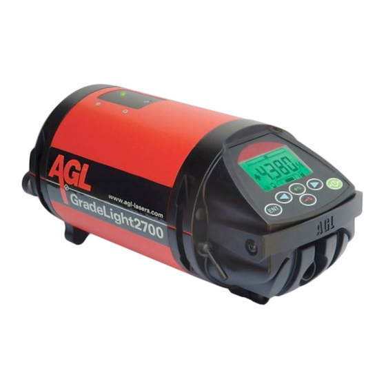
GENERAL INFORMATION The GradeLight pipe laser provides alignment and grade for installation of gravity flow sanitary and storm sewer pipelines, as well as for pipe jacking and tunneling. The GradeLight includes: • Infrared remote control • Adjustable leg set for multiple pipe sizes •... -
Page 4: Laser Overview
Laser Overview Stringline Hook/ Line Accessory Mount Pivot Point Remote Reception Window (rear) LCD Display Keypad Handle Rechargeable Battery Pack Charging/Power Battery Pack Toggle Screw to Slot For 5/8” x 11 Connector Cap Release Screw Tighten Leg Adjustable Leg thread Leg Reference Lines Beam Output Align To Marks on Legs... - Page 5 Keypad and LCD Overview Keypad Functions Power On/Off Enter digit select mode for grade Enter user settings menu Set azimuth line (left & right) Change digit positions when setting grade Set grade as rolling counter or digit select LCD Indications Line Adjustment Range Indicator Shows beam position relative to line adjustment range.
-
Page 6: Power
POWER The GradeLight can be powered from the Li-ion rechargeable battery or the alkaline battery pack. It can also be used while charging -- from AC using the included converter, or from 12VDC using the optional power cable. Charging Charge before first use and when the battery symbol indicates low. The Li-ion battery can be charged in the unit, or removed and charged separately. -
Page 7: Operation
Press On/Off button to power-up the laser. Check the following indications on the LCD: The start-up screen shows AGL. The battery capacity is displayed. Charge when there is one bar left. The laser automatically self-levels, and returns to the same grade and line settings as last used. -
Page 8: Entering Grade
Entering a Grade The grade range is from +40% to -10%. Grade can be set in increments as small as .001% using the digit select or rolling counter entry method. The display lights when entering grade. The LCD is color coded to match the grade entry button: green for positive grade and red for negative grade. -
Page 9: Remote Control And Line Adjustment (Azimuth)
Remote Control Overview The remote is used primarily to move the beam left or right, within the azimuth range, and to put the laser in standby or locked modes. Since it’s an infrared line-of-sight device, there should be no obstructions between it and the laser. It can be pointed at either the front side (through the pipe) or the back side of the laser. -
Page 10: Replacing Batteries In Remote
To Automatically Center the Beam On laser keypad, press simultaneously & On remote, press Replacing the Batteries of the Remote Control The LED on the remote will flash red when the batteries are low. To change the batteries: 1. Open the housing by removing the 6 screws. 2. -
Page 11: Using The Target
Using the Target The target can be used for multiple pipe sizes. It features a unique design: the target panel is mounted at the front of the base, not in the center. This allows you to view it easier at the front of the pipe. It also has a magnetic base for attaching to trench box side wall after pipe set- ting for better airflow, to minimize refraction. -
Page 12: Applications
APPLICATIONS Transfer of Elevation Using an Automatic Level Figure A 1. Mount the level on a tripod outside the manhole or open cut. Adjust it to level and point at the 1st reading manhole hub. Take a reading from a rod held at 2nd Reading Elevation of the hub. -
Page 13: Alignment Methods
(8) is over the manhole center. The transit mount is a 5/8 x 11 male attachment for mounting a standard transit. The AGL Special Transit is mounted, using an adapter assembly. Aligning the beam with the AGL Special Transit 2. -
Page 14: Special Transit With Rod Group
Aligning the beam with a standard transit Align the Transit over the Instrument - Mount the standard transit to the transit mount at the end of the arm. Using a plumb bob, adjust the arm so the transit is directly over the centerline of pipe. -
Page 15: Set-Up Methods
Set-up Methods These instructions describe four ways to set up: height adjustable legs, trivet, rod and crossbrace, or above ground on a tripod. Height Adjustable Legs Manhole Place Front Center Leg Point here The adjustable legs can be used to set up in a manhole base, pipe, invert, or open Pipe Direction... -
Page 16: Invert Set-Up
Invert Set-up Figure I Position the legs the same as you would if setting up inside the pipe. Place the laser in the invert and complete the set-up as shown in the Manhole Base Set-up in the previous section. Open Cut Set-up When using the height adjustable legs in an open cut, Beam Centerline a stable base such as a concrete block, brick, or board... -
Page 17: Trivet
Trivet Figure J Manhole Base Set-up 1. Prepare the laser for use: Attach handle/rod mount, apply power, center the line adjustment, and enter desired grade. Mount the height adjustable rod (center the rod height in its adjustment range) to the trivet. (Figure J) 2. -
Page 18: Above Ground Set-Up
Above Ground Set-up Figure K 1. Prepare laser for use: mount the sighting scope and ABOVE attach to a 5/8”x11 dome head tripod. Center the line GROUND TARGET adjustment, and set grade at exactly zero. ROD READING 2. Measure over from an offset hub and position the (Backsight Elevation) tripod directly over the pipe centerline trying to keep ELEVATION... -
Page 19: Menu Options
• When the reminder appears on the screen, it can be turned off (and the counter reset to 0 hours). • The start-up screen can be changed from “AGL ” to your company information. CALIBRATION See instructions for “Adjusting Level Accuracy” later in the manual. -
Page 20: Changing The Service Interval
Changing AGL Start-up Screen To Your Company Information If a non-AGL name is already being used, follow Steps 1-2 and 5-8 to change to a different name. Enter the Set Up mode following Steps 1-3 of “Set Up Menu” in previous section. -
Page 21: Troubleshooting
TROUBLESHOOTING Indication on LCD Laser Beam Reason Remedy Flashes evenly Laser is leveling Wait until self-leveling is completed. Blinking Pulses in Self-leveling Change position of laser in 2 short flashes range is exceeded direction arrows indicate. When it’s within the self-leveling range, the warning will disappear and self-leveling will begin. -
Page 22: Using A Blower To Eliminate Refraction
The pipe is placed into the ground, which is much cooler than the road or dirt surface. The pipe has AGL Blower heated air and will continue to heat the air until it 1-08915 cools off. -
Page 23: Checking And Calibration
This is within the stated accuracy of ± 1/16” at 100 ft. If the marks are close enough, the beam is accurately projecting level. If they are not close enough, take it to an authorized AGL service center for calibration, or adjust the Stake Stake... - Page 24 Accessing Calibration through the Set Up Menu 1. Turn the laser off, and then turn the laser on again. 2. When the AGL start-up screen is displayed, press the + and ENT buttons simultaneously. Hold until the Set Up screen appears (after the Battery Check).
- Page 25 To save the calibration (beam position), press the lock T UP button on the remote (or the ENT button on the laser keypad). If you don’t want to save the calibration, turn the laser off. To leave the CALIBRATION mode, move the cursor to CALIBRATION >...
-
Page 26: Safety, Care, And Handling
SAFETY, CARE, AND HANDLING Caution Use of controls or adjustments or performance of procedures other than those specified herein may result in hazardous radiation exposure. There is a purge screw inside the battery cavity, under a black decal. DO NOT OPEN! If this screw is removed, the moisture-free nitrogen purge of the unit will be lost. -
Page 27: Warranty
Products forming part of a fixed installation, such place of performance shall be the site of such installation and AGL shall have the right to charge for additional costs for such services under warranty if the site of the Product is other than where the Product was originally shipped or installed. - Page 28 CONSTRUCTION LASERS & MACHINE CONTROL SYSTEMS 2202 Redmond Rd., Jacksonville, AR 72076 sales@agl-lasers.com www.agl-lasers.com Phone: 501.982.4433 Fax: 501.982.0880 Toll Free: 800.643.9696 Printed in USA AM1135 2/09 Specifications subject to change without notice...
Need help?
Do you have a question about the GradeLight 2700 and is the answer not in the manual?
Questions and answers
Where can i get replacement parts. I need a battery pack for the alkaline batteries.