Table of Contents
Advertisement
Quick Links
Advertisement
Table of Contents

Summary of Contents for TECNOvesta Smart Line Series
- Page 1 Italian Cooking Equipment Smart Line Smart Plus+ Owner Manual...
- Page 2 SERIAL NUMBER AND ELECTRIC SPECIFICATIONS pag. 2...
- Page 3 INDEX Introduction Pag. General Safety Instructions Pag. Unpacking Pag. Installation Pag. Start-up operation Pag. Analog control panel operation Pag. Digital control panel operation Pag. How to operate a cooking cycle- bakery smart plus+ Pag. How to operate a cooking cycle- gastronomy smart plus+ Pag.
-
Page 4: General Safety Instructions
Keep the manual in a place where it can be consulted by the operator using the oven. If you lose your manual or you need additional copies, please download it from the Tecnovesta website in the download section at www.tecnovesta.com. - Page 5 The oven can be mounted on an optional oven stand or optional holding cabinet and leveled registering the adjustable feet. All clearances for proper ventilation and air supply must be maintained to minimize fire hazard. Do not locate the oven immediately adjacent to any other heat-generating appliance. TOP VIEW –...
- Page 6 FRONT AND LATERAL VIEWS – EXTERIOR DIMENSIONS (0L0664M/E; 0L0611M/E) FRONT AND LATERAL VIEWS – EXTERIOR DIMENSIONS (0L0464M/E; 0L0411M/E) pag. 6...
- Page 7 FRONT AND LATERAL VIEWS – EXTERIOR DIMENSIONS (0S0443M) FRONT AND LATERAL VIEWS – EXTERIOR DIMENSIONS (0S0464M) pag. 7...
- Page 8 DOOR OPENING SIZES 0S0443M 0S0464M OVEN STANDS AND HEATED CABINETS COMBINATIONS Heated Cabinet Heated Oven Reference Stand Reference Stand Size Levels Levels Reference Cabinet Size 0S0464M 0T0464B 795x690x940 8 – 600x400 0S0464M GN 1/1 0T0411B 795x690x940 8 – GN 1/1 0L0464M/E 0T1264 920x680x940...
- Page 9 Any appliance that is not furnished with a power supply cord must be installed by a qualified electrician. This appliance must be branch circuit protected with proper ampere capacity, in accordance with the wiring diagram located in this manual and the label positioned on the side of the oven. Connect the oven to the electric line through the terminal block on the rear of the oven.
- Page 10 The oven and spray shower (optional) must be connected to the main water supply line. We suggest to always install a water softener to avoid calcium build-up in the valves and pipe connections and other components exposed to water. The water pressure should be between 1 and 2 bars. Once connected the solenoid valve to the main water line, adjust the desired level of water flow by turning the knob of the regulator located between the service panel to terminal block for electric connections and the solenoid valve connector on the back of the oven (for gastronomy ovens).
-
Page 11: Start-Up Operation
START-UP OPERATION Once installed, the oven is ready to use. This appliance is intended for use in commercial establishments where all operators are familiar with the purpose, limitations, and associated hazards of this appliance. This appliance is intended to cook, hold or process foods for the purpose of human consumption. No other use for this appliance is authorized or recommended. - Page 12 ANALOG CONTROL PANEL OPERATION 1. Set TIMER to ON position. 2. Set cooking TEMPERATURE by rotating the knob to desired temperature; when the oven reaches the set temperature, orange light goes off and you can load sheet pans as quickly as possible. 3.
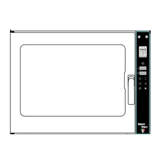
- Page 13 DIGITAL CONTROL PANEL OPERATION 1. Turn oven ON or switch OFF by pushing 2. Adjust cooking TEMPERATURE by pushing to desired cooking temperature; when the oven reaches the set temperature, red led goes off and you can load sheet pans as quickly as possible.
- Page 14 DIGITAL CONTROL PANEL OPERATION 1. Turn oven ON or switch OFF by pushing 2. Choose the cooking cycle among: TIMER COOKING CYCLE push buttons and set parameters with encoder in the following order: CORE PROBE COOKING CYCLE push buttons and set parameters with encoder in the following order: DELTA T COOKING CYCLE push buttons and set parameters with encoder in the following order:...
- Page 15 HOW TO OPERATE A COOKING CYCLE – Bakery Smart Plus+ Once installed and upon completion of the start-up operation, your Vesta convection oven is ready to use. 1- Switch ON the oven by pushing the top button above the displays. The top display shows the temperature inside the oven.
- Page 16 4- CORE PROBE COOKING CYCLE: Insert CORE PROBE in the socket (optional) positioned below the encoder knob on front of your oven, then place the food you want to cook in the oven with the pin inserted in the thicker part of food;...
- Page 17 THE 10 GOLDEN OPERATING RULES OPERATING INSTRUCTIONS C H E F OPERATING TIPS The Vesta convection oven will provide the best results and longest possible service by implementing the following suggestions. 1. Make sure you preheat the oven 20° C over the set cooking temperature before loading the food, especially if frozen.
- Page 18 Baking meat, fish and poultry: Use an appropriate size cooking pan depending on food size. For baking fish use a low temperature between 120-140° C for about 12-15 minutes with the maximum humidity level. Sliced meat can be baked quickly at a temperature of 200-220°C for about 10-15 minutes. Poultry requires a temperature of 180-200°C;...
-
Page 19: Troubleshooting Guide
11. Clean outside glass with a specific product for glass. 12. CLEAN THE COMAND PANEL USING A SOFT CLOTH AND PLAIN WATER. Other external surfaces can be cleaned with the same products used on internal surfaces. TROUBLESHOOTING GUIDE Smart Line Trouble Possible cause Remedy... -
Page 20: Maintenance
MAINTENANCE Replacing a light bulb: 1 - Carefully remove glass lamp cover (as shown on picture); 2 - Unscrew broken light bulb and replace with a new one (as shown on picture); 3 – Place glass cover back on; position cover with cut out edge on bulb side; Replacing or removing door gasket: 1 –... - Page 21 Removing side racks: 1 – Unscrew side screws that hold side rack; (as shown on picture); 2 – Pull up side rack and remove it (as shown on picture); 3 – Reposition side rack pushing down the side rack and fasten screws with a screwdriver. Removing fan cover: 1 –...
-
Page 22: Warranty
This warranty is exclusive and is in lieu of all other warranties, expressed or implied, including the implied warranties of merchantability and fitness for a particular purpose. In no event shall Tecnovesta S.r.l. be liable for loss of use, loss of revenue or profit, or loss of product, or for any indirect, special, incidental, or consequential damages. - Page 23 pag. 23...
- Page 24 Via G. Di Vittorio, 1 – 31044 Montebelluna (Tv) – Italy Headquarter: Via del Pian, 1 Località Bigolino – 31030 Valdobbiadene (Tv) – Italy www.tecnovesta.com pag. 24...
Need help?
Do you have a question about the Smart Line Series and is the answer not in the manual?
Questions and answers