Table of Contents
Advertisement
E2006 Lennox Industries Inc.
Dallas, Texas, USA
®
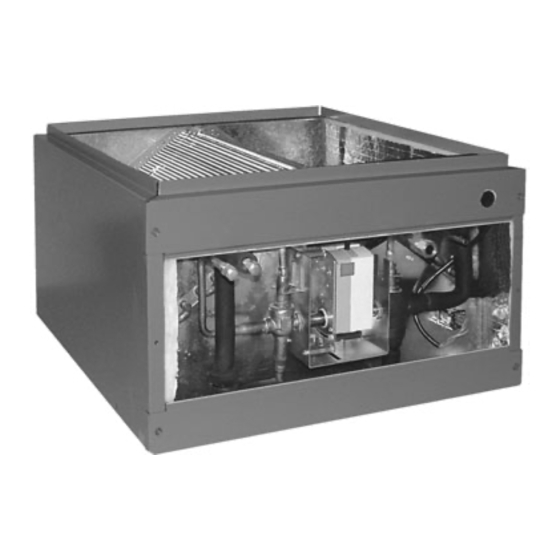
Humiditrol
EDA Series Unit
The Dave Lennox Signature
hanced Dehumidification Accessory (EDA) is designed for
installation with a Lennox R−410A split−system outdoor unit
and an air handler or a furnace with a variable speed blow-
er. This accessory is designed for indoor installations in ei-
ther upflow or horizontal air discharge applications. This
unit is for use only on R−410A systems with thermal
expansion valves.
Prior to installation, study the decision tree on page
16 to confirm that all application requirements for
EDA installation are met.
NOTE − For downflow application, refer to Installation In-
struction Supplement, Installing EDA Unit in Downflow
Configuration 505,134M.
Shipping & Packing List
S
1 − Assembled EDA indoor unit
S
1 − Bag assembly (includes check/flow restrictor for
use on EDA coil, EDA notification label).
S
1 − Outdoor fan relay and wiring harness (used only
with outdoor units equipped with variable speed fan
motors)
Check the components for shipping damage. If any dam-
age is found, immediately contact the last carrier.
Other Required Components
Separately-ordered components are restricted to those
listed in the Engineering Handbook and the price book:
t
S
SignatureStat
thermostat [Outdoor Sensor (46M98)
included],
− Single-stage (81M26)
− Multi−stage (81M27)
− Multi−stage heat-pump (81M28)
S
Twisted Pair Wire (84X49) for outdoor sensor to ther-
mostat − Required for use with SignatureStatt.
S
75VA 24VAC indoor unit transformer (12P61) − Re-
quired when EDA unit is installed with a two-stage heat
pump system.
S
®
Humiditrol
EDA Insulation and Piping Kit (refer to ap-
plications information in Lennox Engineering Hand-
book)
02/06
*2P0206*
t
®
Collection Humiditrol
INSTALLATION/
SERVICE
INSTRUCTIONS
®
Humiditrol
Accessory (EDA) Units
ACCESSORIES
505,021M
02/06
Supersedes 01/06
RETAIN THESE INSTRUCTIONS
FOR FUTURE REFERENCE
Table of Contents
En-
General Information
NOTE − These instructions are intended as a general guide
and do not supersede local codes in any way. Consult au-
thorities having jurisdiction before installation.
®
The Humiditrol
quired, when ambient temperatures are below 95ºF. When
temperatures reach 95ºF, the cooling and dehumidification
requirements will both be satisfied by the increased sys-
tem runtime. In applications that include a Humiditrol
EDA unit, a call to activate the dehumidification mode at or
above 95ºF is unnecessary and would not be issued or al-
lowed by the SignatureStatt room thermostat.
Prior to system checkout, consider the outdoor ambient
temperature. REMEMBER, the EDA unit does NOT
function in temperatures at or above 95ºF. Plan testing
to be conducted when temperatures are between 65ºF and
95ºF to ensure proper EDA set up and checkout operation.
The approved application for the EDA Series unit is
restricted to those listed in the Engineering Hand-
book and price book.
Enhanced Dehumidification
. . . . . . . . . . . . . . . . . . . . . . . . . . . . . . .
. . . . . . . . . . . . . . . . . . . . . . . .
. . . . . . . . . . . . . . . . . . . .
. . . . . . . . . . . . . . . . . . . . . . . . . . .
. . . . . . . . . . . . . . . . . . . . . . . . . . . . . . .
. . . . . . . . . . . . . . . . . . . . . . . . . .
. . . . . . . . . . . . . . . . .
. . . . . . . . . . . . . . . . . . . . . . . . . . . . . . .
. . . . . . . . . . . . . .
. . . . . . . . . . . . . . . . . .
. . . . . . . . . . . . . . . . . . . . .
. . . . . . . . . . . . . . . . . . . . . . .
. . . . . . . . . . . .
. . . . . . . . . . . . . . . . . . . . . . . . . . .
. . . . . . . . . . . . . . . . . . . . . . . . . . . . . .
. . . . . . . . . . . . . . . . . . . . . . . . . . . . . .
. . . . . . . . . . . . . . . . . . . . . . . . . . . . . . . . .
EDA unit will operate to dehumidify, as re-
IMPORTANT
505,021M
*P505021M*
Litho U.S.A.
1
1
1
1
2
. . . . . . . . .
3
4
5
5
. . . . . . . .
5
8
9
9
10
. . . . . . . . . .
10
11
. . . . . . . . . .
11
13
13
13
16
®
Advertisement
Table of Contents

Subscribe to Our Youtube Channel
Summary of Contents for Lennox 21
-
Page 1: Table Of Contents
E2006 Lennox Industries Inc. Dallas, Texas, USA ® Humiditrol EDA Series Unit The Dave Lennox Signature Collection Humiditrol hanced Dehumidification Accessory (EDA) is designed for installation with a Lennox R−410A split−system outdoor unit and an air handler or a furnace with a variable speed blow- er. -
Page 2: Unit Dimensions
WARNING This cased product contains fiberglass wool. Dis- turbing the insulation during installation, mainte- nance, or repair will expose you to fiberglass wool dust. Breathing this may cause lung cancer. (Fiber- glass wool is known to the State of California to cause cancer.) Fiberglass wool may also cause respiratory, skin, and eye irritation. -
Page 3: Installation Dimensions And Arrangement
Installation Dimensions and Arrangement EDA UNIT INDOOR COIL FURNACE TYPICAL UP−FLOW POSITION (Furnace Shown) TYPICAL HORIZONTAL POSITION (Furnace Shown) (TRANSITION See Note 2) Varies by indoor coil model; see LENNOX Engineering Handbook. AIR FLOW UP-FLOW FURNACE NOTES: 1. Transition is required for all air handlers; dimension width and depth is dependent upon the air handler and the EDA model used. -
Page 4: Component Functions
Component Functions Charge Compensator The (shown in figure 5) serves to maintain the proper amount of refrigerant circulating in larger systems. [Some systems do not require a charge compensator, but do require a simi- lar kit to connect into the system (see Engineering Hand- book)] The charge compensator stores excess refrigerant when the EDA coil is active and returns it to the system during... -
Page 5: General Installation Information
General Installation Information WARNING Improper installation, adjustment, alteration, ser- vice or maintenance can cause personal injury, loss of life, or damage to property. Installation and service must be performed by a qualified installer or service agency. The EDA unit may be used in upflow or horizontal dis- charge installations. - Page 6 start ALL REQUIRED PARTS AVAILABLE Installation Process ENSURE ALL POWER IS OFF INSTALL EDA UNIT IN DUCT SYSTEM INSTALL THE CHARGE COMPENSATOR (IF REQUIRED) IN CONVENIENT LOCATION (SEE FIGURE 5) MAKE ALL REFRIGERATION CONNECTIONS, BEING SURE TO INSTALL THE CHECK/FLOW RESTRICTOR (SEE FIGURE 5) LEAK CHECK THE SYSTEM WITH 3−WAY VALVE ASSEMBLY...
- Page 7 Typical Installation (Horizontal Air Handler shown) EDA UNIT Electrical Inlet To Charge Compensator side connection (some applications) Check/Flow Restrictor to Vapor FLOW Line Tee Liquid Line to Indoor TXV Liquid Line From Outdoor Unit air−flow Liquid Line from Outdoor Unit Liquid Line to Indoor TXV MUST BE...
-
Page 8: Leak Testing, Evacuation, Charging
Leak Testing, Evacuating, Charging IMPORTANT The 3−way diverting valve actuator shaft setscrew (see figure 7) is factory set and is not to be adjusted. 3−way Diverting Valve Operation NOTE − During system operation, the 3-way valve requires 24-volt power to drive between cooling and dehumidifica- tion. -
Page 9: Insulating And Sealing The Unit
Insulating and Sealing the Unit IMPORTANT All piping, metering devices, and connections must be insulated to prevent moisture damage caused by sweating. Seal the unit so that warm air is not allowed into the cabi- net. This is especially important when the unit is installed in an unconditioned area. -
Page 10: How The Eda Unit Works
EDA Unit Operation The EDA coil is added to an HVAC system downstream of the indoor coil. In dehumidification mode, the coil becomes an extension of the condenser coil and injects heat into the indoor air stream. This dehumidification mode allows significantly improved control of the humidity in the conditioned space without overcooling the space. -
Page 11: Cooling Mode (Dehumidification Off)
Cooling Mode (Dehumidification OFF) Figure 10 illustrates refrigerant flow in cooling mode (dehu- midification mode OFF), Cooling Cycle with EDA Coil Inactive (Model EDA−036C shown) VAPOR LINE VALVE LIQUID LINE VALVE OUTDOOR UNIT NOTE 1. In Cooling Mode, no air temperature change across EDA coils. NOTE 2. - Page 12 Check List n Checkpoint What to Check Thermostat and Wiring Sensor ® Thermostat Humiditrol ® Thermostat Humiditrol ® Thermostat Humiditrol Indoor Unit Variable-Speed Blower Settings Insulation Charge Compensator Insulation Liquid Line Insulation Vent Line to Suction Line Charge Compen- 1/4"Line sator Check/Flow Re- 3/8"...
-
Page 13: Air Resistance Table
Air Resistance Table 2 shows air volume and total air resistance for the available EDA models. Table 2 Air Resistance Air Volume Model No. EDA−024B 1000 EDA−036C 1000 1200 1400 EDA−060DB 1000 1200 1400 1600 1800 2000 2200 1040 Repair Parts 3−way diverting valve assembly Check/flow restrictor EDA Relay... -
Page 14: Control Wiring
Typical EDA/Condensing Unit Wiring Diagram *OUTDOOR RELAY NOT REQUIRED WITH SINGLE- SPEED OUTDOOR FAN 1st, cut yellow 2nd, rewire yellow wire here. wire as shown OUTDOOR UNIT RED (NOT REQUIRED FOR APPLICATIONS WITHOUT LSOM) PURPLE BLACK FAN RELAY (NOT REQUIRED WITH SINGLE-SPEED OUTDOOR FAN) YELLOW... - Page 15 Typical EDA/Heat Pump Wiring Diagram *OUTDOOR RELAY NOT REQUIRED WITH SINGLE- SPEED OUTDOOR FAN 2nd, rewire yellow wire as shown 1st, cut Blue yellow wire Yellow here. Black Use Wirenuts OUTDOOR WIRING (VSM APPLICATION ONLY) OUTDOOR UNIT FAN RELAY (NOT REQUIRED WITH SINGLE-SPEED OUTDOOR FAN) PURPLE...
-
Page 16: Decision Tree
Humiditrol START dealer Obtain R−410A & R−410A & EDA EDA training trained Desired equipment Zoning matchup listed in application? EDA Engineering Handbook? Application Not Approved DO NOT INSTALL NOTE − Lennox warranties do not cover damage or defect resulting from operation with system components (indoor unit, outdoor unit, and refrigerant control devices) which do not...
Need help?
Do you have a question about the 21 and is the answer not in the manual?
Questions and answers