Table of Contents
Advertisement
Quick Links
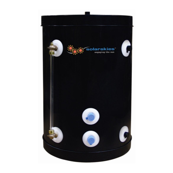
Drain Back Tank
Installation
Maintenance
Drain Back Tank Models:
915-001 10 Gallon Solar Skies Drain Back Tank with sight glass, no heat exchanger
915-002 15 Gallon Solar Skies Drain Back Tank with sight glass, no heat exchanger
915-003 20 Gallon Solar Skies Drain Back Tank with sight glass, no heat exchanger
915-004 30 Gallon Solar Skies Drain Back Tank with sight glass, no heat exchanger
915-022 45 Gallon Solar Skies Drain Back Tank with sight glass, no heat exchanger
915-023 60 Gallon Solar Skies Drain Back Tank with sight glass, no heat exchanger
915-007 10 Gallon Solar Skies Drain Back Tank with additional heat exchanger & sight glass
915-008 15 Gallon Solar Skies Drain Back Tank with additional heat exchanger & sight glass
915-009 20 Gallon Solar Skies Drain Back Tank with additional heat exchanger & sight glass
NOTICE: Solar Skies Mfg. reserves the right to make product changes or updates without notice and will not be held
liable for typographical errors in literature.
Solar Skies Mfg, LLC
106 Donovan Drive • Alexandria, MN 56308 • Ph 320-762-1151 Fax 320-762-1460
CD1065.doc
Last Revision: 12/23/2010
Advertisement
Table of Contents

Summary of Contents for SolarSkies 915-001
- Page 1 Maintenance Drain Back Tank Models: 915-001 10 Gallon Solar Skies Drain Back Tank with sight glass, no heat exchanger 915-002 15 Gallon Solar Skies Drain Back Tank with sight glass, no heat exchanger 915-003 20 Gallon Solar Skies Drain Back Tank with sight glass, no heat exchanger...
- Page 2 The following defined terms are used throughout this manual to bring attention to the presence of hazards of various risk levels or to important information concerning the product. DANGER indicates an imminently hazardous situation which, if not avoided, will result in death or serious injury.
-
Page 3: For The Installer
FOR THE INSTALLER INSTALLATION OR SERVICE OF THIS SOLAR PRODUCT IS REQUIRED TO BE PERFORMED BY LICENSED PROFESSIONALS WHERE SOLAR, PLUMBING, AND ELECTRICAL WORK IS REQUIRED. The installer should be guided by the instructions furnished with the tank, local codes and utility company requirements. Preference should be given to codes and requirements where they differ from the furnished instructions. -
Page 4: Table Of Contents
TABLE OF CONTENTS INTRODUCTION ..................Error! Bookmark not defined. PART 1: GENERAL SAFETY INFORMATION..................5 A. PRECAUTIONS..........................5 B. CHEMICAL VAPOR CORROSION....................6 C. INSULATION BLANKETS....................... 6 D. SCALD PREVENTION........................6 PART 2: GENERAL INFORMATION ....................... 7 A. PIPING ............................7 B. -
Page 5: Part 1: General Safety Information
INTRODUCTION Drain back tanks are designed to allow solar collectors and related piping to drain heat transfer fluid into the drain back reservoir when not in use. Drain back systems are versatile: ideally suited for both cold and warm regions. The drain back process protects solar system components from both freezing and overheating, and saves power by shutting down the solar system when there is no longer a demand for hot water. -
Page 6: Chemical Vapor Corrosion
ALL PIPING AND PLUMBING CONNECTIONS SHOULD BE MADE WITH COPPER OR STAINLESS STEEL PIPE ONLY. No less than ¾” I.D. copper tube of the type meeting local codes must be used for piping. Pipe runs must be solidly attached with proper clamping methods. Soldered connections should be secured with 95/5 lead-free solder. Use only pipe rated for 230 F minimum on both the collector return and supply piping. -
Page 7: Part 2: General Information
PART 2: GENERAL INFORMATION A. PIPING Collector piping requires the use of copper and brass fittings in the collector loop. To avoid leaks and fluid loss, copper and brass ground joint unions should be used to join the collectors. Use only lead-free solder. Engelhard Silvabrite 100 or equivalent is the required soldering material. -
Page 8: Part 3: Specifications
PART 3: SPECIFICATIONS Figure 1 – Drain Back Tank Specifications and Dimensions MODEL # GAL. 915-001 19" 1 1/4" 19 1/4" 5" 15" 915-002 23" 1" 19 1/4" 4 1/2" 17" 915-003 28" 1 1/2" 19 1/4" 4 1/2" 21 3/4"... - Page 9 MODEL GAL. 915-004 4 1/2" 33 3/4" 39 1/2" 42 1/2" 19 1/4" 915-022 4 1/2" 45 5/8" 51 7/8" 53 3/4" 19 1/4" 915-023 4 3/4" 46 1/4" 52 1/8" 53 1/2" 23 1/4" TANK SHIPPING MODEL # INLET TANK OUTLET WEIGHT 915-004...
-
Page 10: Part 4: Installation
PART 4: INSTALLATION A. DRAIN BACK TANK LOCATION To minimize expense and heat loss, locate the drain back tank as centrally to the solar tank and near the solar collectors as possible. The tank must also be located in as warm a location as possible, away from areas which would subject the drain back reservoir to freezing temperatures. -
Page 11: Installation Of The Tank
C. INSTALLATION OF THE TANK On stainless steel tanks ONLY: Never use dielectric unions or galvanized steel fittings on any domestic water connections or auxiliary connections. ONLY use copper or brass fittings. Teflon thread sealant must be used on all connections. 1. -
Page 12: Solar System Pump
Households with small children, disabled, or elderly persons may require a 120 F or lower temperature setting to prevent scalding. The circulating pump becomes very hot when running. Allow sufficient time to cool before touching. D. SOLAR SYSTEM PUMP Solar pumps must be installed below drain back tank. Remove integral check if so equipped. The solar system pump must be sized to lift water to the top of the collector array. -
Page 13: Part 5: Installation Diagrams
PART 5: INSTALLATION DIAGRAMS A. DRAIN BACK TANK WITH BACK UP GAS WATER HEATER Figure 3 – Drain Back System with Gas Back Up Solar Skies Mfg, LLC 106 Donovan Drive • Alexandria, MN 56308 • Ph 320-762-1151 Fax 320-762-1460 CD1065.doc Last Revision: 12/23/2010... - Page 14 B. DRAIN BACK TANK WITH BOILER AND INDIRECT WATER HEATER Figure 4 – Drain Back System with Boiler Back Up Solar Skies Mfg, LLC 106 Donovan Drive • Alexandria, MN 56308 • Ph 320-762-1151 Fax 320-762-1460 CD1065.doc Last Revision: 12/23/2010...
-
Page 15: Drain Back Tank With Heat Exchanger
C. DRAIN BACK TANK WITH HEAT EXCHANGER Figure 5 – Drain Back System with Heat Exchanger Solar Skies Mfg, LLC 106 Donovan Drive • Alexandria, MN 56308 • Ph 320-762-1151 Fax 320-762-1460 CD1065.doc Last Revision: 12/23/2010... -
Page 16: Part 6: Heat Transfer Fluid Quality
PART 6: HEAT TRANSFER FLUID QUALITY Two heat transfer fluids may be used in drain back systems: Distilled water or glycol/water mix. Water in direct flow through the drain back tank must first meet potable water requirements and, in addition, the following: TOTAL DISSOLVED SOLIDS <600 ppm TOTAL HARDNESS... -
Page 17: Part 8: Service/Maintenance Procedures
PART 8: SERVICE/MAINTENANCE PROCEDURES A. SHUT DOWN PROCEDURE To shut down the drain back system, simply unplug the differential controller. The pump will stop and water will drain out of the collectors into the reservoir. Never open the pressure relief valve while the system is in operation or hot water is present. Allow to cool prior to opening. -
Page 18: Installation And Maintenance Notes
INSTALLATION AND MAINTENANCE NOTES Solar Skies Mfg, LLC 106 Donovan Drive • Alexandria, MN 56308 • Ph 320-762-1151 Fax 320-762-1460 CD1065.doc Last Revision: 12/23/2010... - Page 19 SOLAR SKIES MFG. CUSTOMER INSTALLATION RECORD FORM The following form should be completed by the installer for you to keep as a record of the installation in case of a warranty claim. After reading the important notes at the bottom of the page, please also sign this document. Customer’s Name: Installation Address: Date of Installation:...
Need help?
Do you have a question about the 915-001 and is the answer not in the manual?
Questions and answers