
Summary of Contents for One Touch H800
- Page 1 FEB-4720 Main Board...
- Page 2 Federal Communications Commission (FCC) This equipment has been tested and found to comply with the limits for a Class A digital device, pursuant to Part 15 of the FCC Rules. These limits are designed to provide reasonable protection against harmful interference in a residential installation. This equipment generates, uses, and can radiate radio frequency energy and, if not installed and used in accordance with the instructions, may cause harmful interference to radio communications.
- Page 3 Important Safety Information SAFETY INSTRUCTIONS Please read these safety instructions carefully. Keep this User’s Manual for later reference. Disconnect this equipment from the AC outlet before cleaning. Don’t use liquid or spray detergent for cleaning. Use only a moistened sheet or cloth. For pluggable equipment, the socket-outlet should be installed near the equipment and should be easily accessible.
- Page 4 Copyright The information in this guide is subject to change without prior notice. The manufacturer shall not be liable for technical or editorial errors or omissions contained herein, nor for incidental or consequential damages resulting from the furnishing, performance, or use of this material. This manual contains information protected by copyright.
-
Page 5: Table Of Contents
Chapter 1 Chapter 1 Introduction Model H800 Characteristics ....................2 How to Use This Manual ....................... 3 A Visual Tour of Model H800....................4 What comes with Model H800..................4 Dimensions........................6 Connector Panels ........................7 Primary Connector Panel ....................7 Secondary Connector Panel................... - Page 6 ELO Touch Tools Installation ....................40 ELO Touch Tools Installation for Windows 98.............. 40 ELO Touch Tools Installation for Windows 2000 and Windows XP ......42 ELO Control Panel ....................... 45 TouchKit Tools Installation ....................48 TouchKit Tools Installation for all Windows Operating Systems ........48 TouchKit Control Panel ....................
-
Page 7: Introduction
FEB-4720 Main Board Model H800 Characteristics Model H800 uses a high speed processor capable of handling a high capacity of data efficiently. Model H800’s solid quality Aluminum housing distinguishes it from ordinary plastic housings. Model H800 can function with multiple displays under Windows & Linux operating systems. -
Page 8: How To Use This Manual
FEB-4720 Main Board How to Use This Manual This manual contains all the information you need to set up and use Model H800. In addition, you can also consult the manuals for the operating system and added hardware. Chapter 1 Provides an introduction to Model H800 and this manual. -
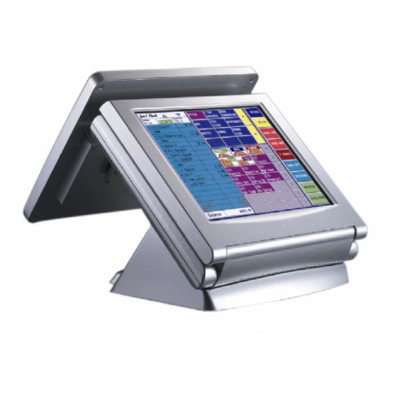
Page 9: A Visual Tour Of Model H800
FEB-4720 Main Board A Visual Tour of Model H800 Before you start, take a few moments to become familiar with Model H800. What comes with Model H800 The following items are standard with Model H800: Main system with primary LCD panel... - Page 10 FEB-4720 Main Board The following items are optional: Magnetic card reader (MCR) and bracket External CD-ROM drive with cable External USB floppy disk drive with cable VFD customer display Second LCD panel Second Touch panel Optional accessories...
-
Page 11: Dimensions
FEB-4720 Main Board Dimensions Model H800 Dimensions Second LCD Dimensions Model H800 and MCR Dimensions... -
Page 12: Connector Panels
Connector Panels Primary Connector Panel The primary connector panel is located on the bottom of the back on the main unit. To clearly see the panel you must turn Model H800 upside down or remove the base. RJ11 LAN RJ45... -
Page 13: Secondary Connector Panel
FEB-4720 Main Board Secondary Connector Panel The secondary connector panel is located on left side of the back of the main unit. It comes with a cover that needs to be removed to install a second LCD panel, touch screen, PS/2 Keyboard, CD ROM Drive or a VFD customer display. -
Page 14: Hardware Setup
Please make sure that the system power is turned off and the power supply is disconnected when making any hardware changes on Model H800. Hard Disk Drive Installation Model H800 comes with an empty hard disk Drive (HDD) unless a special request has been made. Installing a HDD 1. - Page 15 6. Connect the HDD power cable and IDE cable. The red stripe on the ribbon cable should be aligned with PIN 1 on the IDE connector of HDD. 7. Reinstall the HDD frame with HDD attached in Model H800 (3 screws). 8. Replace cover and 6 screws. 9. Connect the main unit power.
-
Page 16: Compact Flash Installation
FEB-4720 Main Board Compact Flash Installation Model H800 will configure Compact Flash in IDE mode as secondary master after it is installed. The next available drive letter will be automatically assigned to Compact Flash. Installing Compact Flash 1. Turn off system power. -
Page 17: Second Lcd Panel Installation
FEB-4720 Main Board Second LCD Panel Installation An optional second LCD panel can be easily installed on Model H800. Installing second LCD panel 1. Turn off system power. 2. Remove the secondary I/O port cover (1 screw). 3. Attach the second LCD to the back... - Page 18 FEB-4720 Main Board 4. Attach the second LCD panel VGA cable in the VGA2 port on the I/O panel. 5. Attach the second LCD power cable in the Power port on the I/O panel. 6. Turn on system power. Note: If the second LCD does not work normally, please refer to troubleshooting.
-
Page 19: Osd Settings For Second Lcd Panel
FEB-4720 Main Board OSD Settings for Second LCD Panel Model H800 secondary LCD panel has built-in OSD (on screen display) controls to adjust various display parameters. The control buttons are located on the right side of the back cover. OSD Settings There are four buttons on the OSD panel: Select, Down, Up, and Enter. - Page 20 FEB-4720 Main Board Geometry Menu Auto-Adjustment H. Position 0~252 V. Position 1~26 H. Total 1004~1108 Auto Phase Delay 0~61 Main Menu Contrast Menu Auto-Balance Contrast 0~511 Green 0~511 Blue 0~511 Balance 0~127 Green 0~127 Blue 0~127 Main Menu 0~127 Language Menu English Spanish Main Menu...
-
Page 21: Second Lcd With Touch Screen Installation
FEB-4720 Main Board Second LCD with Touch Screen Installation An optional second touch screen can be easily installed on Model H800. Installing second LCD with touch panel 1. Turn off system power. 2. Make sure JP1 and JP2 on the secondary I/O board 9000PB0270 are correctly set. -
Page 22: Magnetic Card Reader Installation
FEB-4720 Main Board Magnetic Card Reader Installation An optional Magnetic Card Reader (MCR) can be installed on the right side of Model H800. Magnetic Card Reader (MCR) Installing an MCR 9. Turn off system power. 10. Unplug loopback from the MCR socket. The MCR socket is found on the right side on the back of Model H800. -
Page 23: Mcr Parameter Modification
FEB-4720 Main Board MCR Parameter Modification This option is for users who need to customize the MCR parameters for a particular task. Some of the useful parameters include: The selection of country code, other than the default English. The choice of track combinations. The preamble/postamble codes. -
Page 24: Vfd Customer Display Installation
FEB-4720 Main Board VFD Customer Display Installation An optional VFD customer display can be installed on the back of Model H800. A VFD customer display cannot be installed at the same time as a second LCD panel or second LCD touch panel. -
Page 25: Cd-Rom Installation
Cash Drawer Installation 1. Before the cash drawer has been connected to Model H800, please make sure the drive voltage and cable pin assignment of the cash drawer is matched to the definition of the cash drawer port of Model H800. Please refer to page 54 Cash drawer RJ11 connector. -
Page 26: Cash Drawer Activation
Check the state of bit4, if Low a drawer is open, if High then both drawers are closed. CMOS Setup This Model H800 system has a FEB-4720 motherboard installed that uses AWARD BIOS. Please refer to the FEB-4720 M/B user's manual for a detailed description of BIOS CMOS setup. -
Page 27: Software Setup
FEB-4720 Main Board Model H800 comes with a variety of drivers for different operating systems. You will find 1 CD with Model H800. The CD has all the necessary drivers to setup Model H800. Please follow this installation sequence exactly. - Page 28 FEB-4720 Main Board 5. Read the License Agreement and click Yes. 6. Click Next and the drivers for the Intel Chip set will install. 7. When the 'Setup COMPLETE' message appears click Finish to restart your computer.
-
Page 29: Vga Driver Installation
FEB-4720 Main Board VGA Driver Installation 4720 uses only one chipset “852GME” that is capable of driving a single or dual panel display. Only one driver needs to be installed. 852GME driver installation Windows 98 & ME 1. Locate the VGA folder on the utilities CD. 2. - Page 30 FEB-4720 Main Board 6. Read the License Agreement and click Yes. 7. Click Finish to complete the installation procedure and restart the system.
- Page 31 FEB-4720 Main Board 8. When entering Windows, Windows will find new hardware. Insert Disk Open D:\ \GRAPHIC\INTEL\WIN9X\WIN9X\ikch8xx.cat folder DRIVER Click OK...
-
Page 32: 852Gme Driver Installation Windows 2000 & Xp
FEB-4720 Main Board 852GME driver installation Windows 2000 & XP 1. Open D:\ \GRAPHIC\INTEL\WIN2KXP folder. DRIVER 2. Run setup.exe 3. Select Next to continue. 4. Select Next to continue. - Page 33 FEB-4720 Main Board 5. Read the License Agreement and click Yes. 6. Click Finish to complete the installation procedure and restart the system.
-
Page 34: Enable Second Lcd Panel Setting Windows 2000/Windows Xp
FEB-4720 Main Board Enable second LCD panel setting Windows 2000/Windows XP. After you have installed the VGA driver you must adjust the settings. 3. Right click your mouse anywhere on the desktop then click properties. 4. Click the settings tab. - Page 35 FEB-4720 Main Board 5. Click Advanced. 6. Click Intel(R) Extreme Graphics.
- Page 36 FEB-4720 Main Board 7. Click Graphics Properties. 8. Click Extended Desktop and select Notebook for primary device, monitor for secondary device.
- Page 37 FEB-4720 Main Board 9. Click OK. 8. Select the second LCD panel. This is done either by clicking on the number 2 or selecting from the dropdown menu. For the second LCD panel make sure that Extend my Windows desktop onto this monitor is selected.
-
Page 38: Lan Driver Installation
FEB-4720 Main Board LAN Driver Installation Realtek LAN Driver Installation Windows 98 1. Open Device Manger in the System Properties. Select PCI Ethernet Controller Click Properties 2. Select the General tab. Click Reinstall Driver. - Page 39 FEB-4720 Main Board 3. Click Next. 4. Select Search for a better driver then the one your device is using now (Recommended). Click Next. 5. Select The updated driver [Recommended]. Click Next.
-
Page 40: Realtek Lan Driver Installation Windows 2000 And Windows Xp
FEB-4720 Main Board 6. Click Next. 7. Click Finish. 8. Click Yes to restart your computer. Realtek LAN Driver Installation Windows 2000 and Windows XP After Windows 2000 is installed the Realtek LAN driver will be automatically installed. -
Page 41: Audio Driver Installation
FEB-4720 Main Board Audio Driver Installation Audio Driver Installation for all Windows Operating Systems. 1. Open D:\ \AUDIO\WDM DRIVER 2. double click Setup.exe. 3. Select Next to continue. - Page 42 FEB-4720 Main Board Note: For Windows 2K. If you receive this warning message, please click Yes to continue. Note: For XP If you receive this warning message, please click Continue Anyway. 4. Click Finish and restart the system.
-
Page 43: Usb Driver Installation
FEB-4720 Main Board USB Driver Installation USB 2.0 Installation for Windows 98 & ME Open D:\ \USB20\WIN9X DRIVER double click Setup.exe. Read the License Agreement and click Yes. Click Close... -
Page 44: Usb 2.0 Installation For Windows 2000 And Xp
FEB-4720 Main Board USB 2.0 Installation for Windows 2000 and XP For Windows 2000, SP4 must be installed for USB 2.0 support. For Windows XP, SP1 or SP2 must be installed for USB 2.0 support. Note, with lower version service packs only USB 1.1 is supported. This will be indicated in the device manager as an exclamation icon (!) beside the USB device. -
Page 45: Elo Touch Tools Installation
FEB-4720 Main Board ELO Touch Tools Installation ELO Touch Tools Installation for Windows 98 1. Insert the Utility CD and locate the touch screen folder “D:\Utility\TOUCHSCREEN\ELO Touch\ELO Win 9X_me”. 2. Run Setup.exe 3. Click Next. 4. Read the “License Agreement” and click Yes if you accept it. 5. - Page 46 FEB-4720 Main Board 6. Select the COM port for the monitor. It is recommended that you select COM3 for primary touch screen and COM4 for second touch screen. Then click Next. 7. Wait until the ELO Touch Tools have been installed. 8.
-
Page 47: Elo Touch Tools Installation For Windows 2000 And Windows Xp
FEB-4720 Main Board ELO Touch Tools Installation for Windows 2000 and Windows XP Locate D:\Utility\TOUCHSCREEN\ELO Touch Select the relevant ELO folder for the operating system that you are using. Example. If you are installing for a Windows 2000 or XP then select Elo Touch 2K_XP Run Setup.exe Click Next Check “Install serial Touch screen Drivers.”... - Page 48 FEB-4720 Main Board Select “Auto-detect Elo devices.” and click Next. Select the COM port for the touch monitor. It is recommended that you select COM3 for the touch screen, as this port is internally configured for touch operation. Wait until the ELO Touch Tools have been installed.
- Page 49 FEB-4720 Main Board 10. Select View ELO touch screen control panel and click Finish. IT MAY BE NECESSARY TO RESTART YOUR COMPUTER TO UTILIZE YOUR TOUCHSCREEN FEATURES. 11. Click NEXT while this window appears after system finishs rebooting. 12. Click YES to restart your computer again. After the system finishes rebooting follow the directions to calibrate ELO Touch Tools.
-
Page 50: Elo Control Panel
FEB-4720 Main Board ELO Control Panel This section explains the different options in the ELO control Panel. General tab The general tab allows you to: Change the COM port your touch screen is set to. Calibrate the touch screen with the Align button. - Page 51 FEB-4720 Main Board Mode tab The Buttons tab allows you to: Adjust all mouse emulation controls. Change cursor properties Enable or disable right mouse button utility. Sound tab The Sound tab allows you to: To change sound properties for ELO touch tools.
- Page 52 FEB-4720 Main Board Properties tab The Diagnostics tab allows you to: View Controller Information. About tab The About tab displays Information about ELO Touchsystems...
-
Page 53: Touchkit Tools Installation
FEB-4720 Main Board TouchKit Tools Installation TouchKit Tools Installation for all Windows Operating Systems 1. Locate D:\Utility\TOUCHSCREEN\TouchKit\Driver Select the relevant eGalax folder for the operating system that you are using. Example. If you are installing for a Windows 98 system, then select Win9x_Me. If you are installing under Windows 2000 or XP then select Win2000_XP 3. - Page 54 FEB-4720 Main Board 6. Click Next 7. Click Next 8. Click Next...
- Page 55 FEB-4720 Main Board 9. Click Yes 10. Click Finish to restart your computer again. After the system finishes rebooting follow the directions to calibrate the Touch screen.
-
Page 56: Touchkit Control Panel
FEB-4720 Main Board TouchKit Control Panel This section explains the different options in the TouchKit control Panel. General tab The general tab allows you to: Change the COM port your touch screen is set to. Calibrate the touch screen with the 4 pts Cal button. -
Page 57: Specifications
FEB-4720 Main Board System Configuration Intel Pentium 4 / Celeron Processor, supports 400/533 MHz FSB CPU (PGA 478) Bus speed PCI: 33 MHz DMA channels Interrupt levels ® Chipset INTEL 852GME (GMCH). Real-time clock INTEL 82801DB (ICH4) DRAM One 184-pin DIMM socket to support DDR 266/333 SDRAM. The maximum memory is up to 1 GB. - Page 58 FEB-4720 Main Board Keyboard Port One PS/2 keyboard port. LAN Port 10/100Mbps Ethernet Controller Realtek RTL8139C. VGA Port Standard VGA Port for second LCD panel. Supports 24x Slim type external CD-Rom drive. CD-ROM Port Audio Port Integrated Sound Blaster compatible, AC97 Audio Codec. Construction Injection-Molded, Die-cast aluminum enclosure, spill resistance.
-
Page 59: I/O Board Configuration
FEB-4720 Main Board I/O board Configuration The main I/O board 9000PB0560 connects the primary I/O ports to the mainboard. Including: DC power input, COM1 and COM2, LPT1, PS/2 mouse, audio, cash drawer port, USB and LAN port. 9000PB0560 I/O Board Pin Definition 9000PB0560 CON101 System DC power connector... - Page 60 FEB-4720 Main Board...
- Page 61 FEB-4720 Main Board CON7 Cash drawer RJ11 connector PIN No. DESCRIPTION (Frame Ground) (Pulse to 0V for 200ms to activate solenoid 1) SW+ (One side of the cash drawer switch) DC +12V (L1+/L2+)(Common to both solenoids) (Pulse to 0V for 200ms to activate solenoid 2) SW- (The other side of the cash drawer switch) CON3 parallel port LPT1 D-SUB25 connector...
- Page 62 FEB-4720 Main Board CON13 Audio line output EAR connector PIN No. DESCRIPTION EAROUT-L EAROUT-R CON2 RJ45 LAN connector PIN No. Description LAN_TX+ LAN_TX- LAN_RX+ LAN_L45 LAN_L45 LAN_RX- LAN_L78 LAN_L78 CON4&CON41 RS232 port COM1 and COM2 D-SUB connector PIN No. Description SOUT RI/DC output (RI is the default setting) PIN9 signal can be selected as standard RI or DC power output depending on the JP2 and JP3...
- Page 63 FEB-4720 Main Board Description PIN9 of COM2=DC +12V PIN9 of COM2=RI(Default setting) PIN9 of COM2=DC +5V CON5 USB port PIN No. Description Description USB_0- USB_1- USB_0+ USB_1+ CON1 I/O Bus connector PIN No. Description PIN No. Description EAROUT_L DIO_IN00 DIO_OUT01 DIO_OUT00 COM4_DTR COM4_DSR...
- Page 64 Internal keyboard connector for magnetic card reader A 6 wire cable connects to the small MCR connector board. For an external keyboard to function with Model H800 a loopback or an MCR must be installed on the MCR connector board. PIN No. Description...
-
Page 65: 9000Pb0270 I/O Board Pin Definition
FEB-4720 Main Board 9000PB0270 I/O Board Pin Definition The 9000PB0270 secondary I/O board includes external CD-ROM port, 2 LCD/VGA port, 2 LCD DC power, PS/2 Keyboard, and COM4/VFD ports. External CD ROM connector Description Description IDE RESET DATA7 DATA8 DATA6 DATA9 DATA5 DATA10... - Page 66 FEB-4720 Main Board 2nd LCD/VGA connector PIN No. Description GREEN BLUE SM DATA SM CLK V-SYNC H-SYNC DC power output for 2nd LCD panel PIN No. Description +12V CN10 PS/2 keyboard connector PIN No. Description KB-DATA KB-CLK...
- Page 67 FEB-4720 Main Board RJ45 connector for VFD customer display or second LCD touch screen. The port can be used for either a VFD customer display or second LCD touch screen. Since VFD and second touch screen controller need different DC power (VFD needs DC +12v, touch screen controller needs DC +5v) the jumpers need to be set accordingly.
- Page 68 FEB-4720 Main Board 44PIN 2.00mm IDE connector connects to the mainboard secondary IDE connector CN3 PIN No. Description PIN No. Description RESET# DATA 7 DATA 8 DATA 6 DATA 9 DATA 5 DATA 10 DATA 4 DATA 11 DATA 3 DATA 12 DATA 2 DATA 13...
- Page 69 FEB-4720 Main Board 2nd VGA 2x8 PIN header connector connects to the mainboard CN6 PIN No. Description GREEN BLUE SM DATA SM CLK V-SYNC H-SYNC COM4 2x5 PIN header connector connects to the mainboard CON22 Pin No. Description PinNo. Description COM4_DCD COM4_DSR COM4_SIN...
-
Page 70: Troubleshooting
Please note that the following troubleshooting guide is designed for people with strong computer hardware knowledge such as System Administrators and Engineers. Power is on, but there is no Panel Display Check that the external power adapter LED is on when the power adapter power switch is in the on position. -
Page 71: Cannot Detect Hdd
PEB-4720 Main Board E-2-7) The LCD panel could be defective. To check where the problem could be: Please connect the CRT VGA monitor to the 2nd LCD VGA port. If the CRT monitor display is normal, one of the problems above is occurring, otherwise it could be the mainboard is not functioning properly. -
Page 72: Elo Touch Panel Cannot Calibrate Correctly
PEB-4720 Main Board ELO Touch Panel Cannot Calibrate Correctly Please replace the ELO controller, and re-calibrate. If this works, change back to the original ELO controller, and re-calibrate. If the ELO touch panel still cannot calibrate correctly after changing to a new ELO controller, the touch panel may be not installed properly or it could be defective. -
Page 73: Ps/2 Keyboard Is Not Functioning Normally
PEB-4720 Main Board E-2) Check that the RJ45 cable from the 2 Touch panel is connected properly to the COM4/VFD port. E-3) Check that the COM4 cable is properly connected between 9000PB0270 secondary I/O board CN7 and mainboard J43. ELO controller could be defective or the ELO Touch panel could be defective. PS/2 Keyboard is not Functioning Normally Make sure the keyboard is properly connected to the PS2 keyboard port before the system is powered up. -
Page 74: External Cd-Rom Is Not Functioning Properly
PEB-4720 Main Board follow the steps below. B-1) Make sure the power switch on the VFD display is on before powering the main system. B-2) Make sure that the 9000PB0270 secondary I/O board JP1 & JP2 jumper settings are correct. The proper settings are: JP1 PINs 1-2 shorted JP2 PINs 1-2, PINs 3-5 and PINs 4-6 shorted... -
Page 75: Cash Drawer Port Is Not Functioning Properly
PEB-4720 Main Board Cash Drawer Port is not Functioning Properly Make sure the pin assignment matches between the cash drawer and the RJ11 cash drawer port. Use the supplied cash drawer utility program to test the digital i/o port is functioning. Check that Pins 2 &...
Need help?
Do you have a question about the H800 and is the answer not in the manual?
Questions and answers