Table of Contents
Advertisement
Advertisement
Table of Contents

Subscribe to Our Youtube Channel
Summary of Contents for Firstcom FC 138
- Page 2 FC 138 TWO-WAY RADIO INSTRUCION MANUAL...
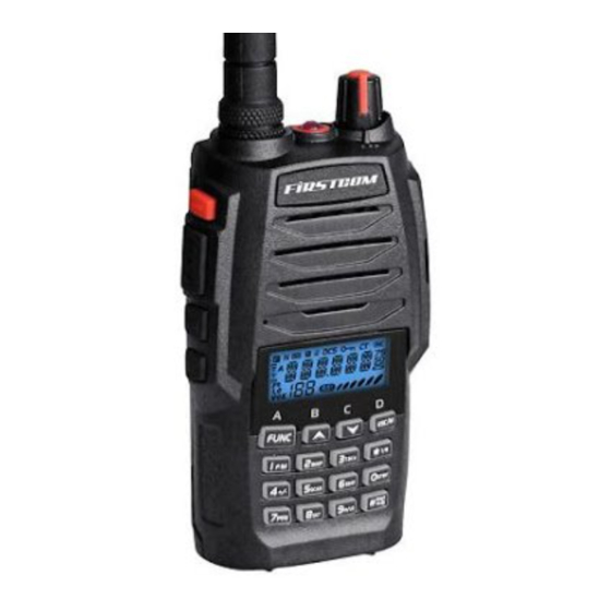
- Page 4 FC 138/418 introduces innovative DSP (Digital Signal Processing) baseband technique to achieve high- fidelity voice processing and encryption. As a compact and fashionable transceiver, FC 138/418 allows you to enjoy instant communication at ease and realize best cost efficiency. It is surely a good choice for communication in Hotels, Amusement buildings, Emporium, Super shopping center, Estate management and other trades.
- Page 5 SAFETY INFORMATION FOR USER transceiver is excellently designed with advanced technology. Please observe the following precautions to perform your obligation, prevent personal injury and ensure the safety of transceiver usage. 1. Keep the transceiver and accessories away from children. 2. Please do not try to open or modify the transceiver without permission, non-professionals process may also cause damage.
-
Page 6: Table Of Contents
CONTENTS UNPACKING ..................................01 Supplied Accessories ............................... 01 STANDARD ACCESSORIES/OPTIONAL ACCESSORIES ....................02 Standard Accessories ............................... 02 Additional Accessories ..............................02 OPERATION MODE (AMATEUR TRANSCEIVER OR PROFESSIONAL TRANSCEIVER) ..........03 WORKING MODE (AMATEUR TRANSCEIVER OR PROFESSIONAL TRANSCEIVER)..........04 FIRST LEVEL MENU:SHORTCUT OPERATIONS ......................05 SECOND LEVEL MENU: CHANNEL OPERATIONS ...................... - Page 7 CONTENTS BASIC OPERATIONS ................................. 22 Turn the Radio On & OFF ..............................22 Adjusting Volume ................................22 Work mode switch ................................23 Channel Selection ................................23 Frequency adjust ................................23 Frequency Input by Keypad .............................. 23 Channel input by keypad ..............................24 FM scan function ................................
- Page 8 CONTENTS DTMF Code Enquiry and Setup ............................31 Transmitting DTMF Signaling ............................31 Frequency Reverse/Talk around On/off ..........................32 Keypad Lockout ................................32 CHANNEL OPERATIONS ..............................34 CTCSS/DCS Decode Setup ............................. 34 CTCSS/DCS Encode Setup ............................. 35 CTCSS/DCS Encode/Decode Synchronous Setup ......................36 Offset Frequency Setup ..............................
- Page 9 CONTENTS DTMF Transmitting Time ..............................48 Priority Channel Setup ..............................49 Current Battery Voltage Display ............................50 Resume Factory Default ..............................50 Programming Software Installing & Starting (THIS INSTRUCTION TAKES WINDOWS XP AS AN EXAMPLE) ........51 Programming Software Installing & Starting (THIS INSTRUCTION TAKES WINDOWS XP AS AN EXAMPLE) ..52 TECHNICAL SPECIFICATIONS ............................
-
Page 10: Unpacking
UNPACKING Carefully unpack the transceiver. We recommend you identify the items listed in the table as bellows before discarding the packing material. If any items are missing or have been damaged during shipment, please contact local dealers immediately. Supplied Accessories Item Number Quantity... -
Page 11: Standard Accessories/Optional Accessories
STANDARD ACCESSORIES/OPTIONAL ACCESSORIES Standard Accessories Antenna Charger Instruction Li-ion Battery AC Adaptor Belt Clip QA07V(136~174MHz) QBC-33L QA07U(400~480MHz) etc (1700mAh) Manual (12V/500mA) (including screws) FB-33L QPS-05 BC06 *1.Note: For frequency band of antenna, please refer to label indicated in the bottom of the antenna. *2.Note:Car Charger should be workable with QBC-33L charger. -
Page 12: Operation Mode (Amateur Transceiver Or Professional Transceiver)
OPERATION MODE (AMATEUR TRANSCEIVER OR PROFESSIONAL TRANSCEIVER) According to practical application,you can set the radio operates as Amateur Transceiver or Professional Transceiver. There are also 3 levels operation menu to set functions as per you need. It is easy and convenient. 1.Operation Mode: A. -
Page 13: Working Mode (Amateur Transceiver Or Professional Transceiver)
WORKING MODE (AMATEUR TRANSCEIVER OR PROFESSIONAL TRANSCEIVER) C.VFO Mode(Frequency mode): This mode shows only frequency on the display. Shortcut operation and Channel setting will be changed & stored as the latest value permanently.Once the radio is turned off or changed to new VFO frequency, the value is remained until next change.(As pic 3) 3.Professional Transceiver Mode:When set display mode as "CH",it enters into Professional Transceiver mode.At this mode,except scan,talk around/frequency reverse,DTMF encode or editing,BEEP on/off and keypad lock,other functions should be set by PC software (As pic 4). -
Page 14: First Level Menu:shortcut Operations
FIRST LEVEL MENU:SHORTCUT OPERATIONS Function Setup Entry Display Parameter Instruction Page FM Radio On/Off FM Radio Beep Setup Beep ON/OFF CTCSS/DCS Scan CTCSS Scan CTCSS/DCS Scan DCS Scan (+):Transmitting frequency higher than Offset Frequency Direction Setup receiving frequency (-):Transmitting frequency lower than Offset Frequency Direction Setup receiving frequency Scan... -
Page 15: Second Level Menu: Channel Operations
SECOND LEVEL MENU: CHANNEL OPERATIONS Function Setup Entry Function Option Display CTCSS/DCS Decode Setup CTCSS/DCS Encode Setup CTCSS/DCS Encode/Decode Synchronous Setup Offset Frequency Wide/ Narrow Band Selection Frequency Reverse/Talk Around Busy Channel Lockout PTT ID Setup TX Off Function Professional FM Transceiver... - Page 16 SECOND LEVEL MENU: CHANNEL OPERATIONS Confirm to Page Parameter Adjustment Parameter Instruction back Press Key to move cursor to the value of menu, Press Key to choose CTCSS/DCS/OFF,Press CTCSS(50 Groups in total): 67Hz-254.1Hz Key to choose the value you want,Press DCS(232Groups in total): 017N-765I Key to choose correct DCS inverted and positive code.
- Page 17 SECOND LEVEL MENU: CHANNEL OPERATIONS OFF: Off BCL: Prohibit transmitting when receiving the matched Press Key to move cursor to the value of menu, carrier wave Press Key to choose the value you want. BTL: Prohibit transmitting when receiving matched carrier wave but with unmatched signaling.
-
Page 18: Third Level Menu:background Operations
THIRD LEVEL MENU:BACKGROUND OPERATIONS Function Menu Entry Function Option Display Time-Out Timer (TOT) Press PF2 and hold this key for 3 seconds Voice Operated Transmission (VOX) Setup Press PF2 and hold this key for 3 seconds Voice Operated Transmission (VOX) Delay Press PF2 and hold this key for 3 seconds Voice Operated Transmission (VOX) Beep Press PF2 and hold this key for 3 seconds... - Page 19 THIRD LEVEL MENU:BACKGROUND OPERATIONS Parameter Adjustment Parameter Instruction Confirm to back Page Press Key to move cursor to the value of menu, 15S-600S to be optional OFF: TOT Off Press key to choose the value you want Press Key to move cursor to the value of menu, 1-9 Level, 9 levels of VOX in total OFF: VOX OFF Press...
- Page 20 THIRD LEVEL MENU:BACKGROUND OPERATIONS Press Key to move cursor to the value of menu, It can be optional that start scanning after dwelling 5S/10S/15S Press key to choose the value you want FREQ: For Amateur Mobile Transceiver Press Key to move cursor to the value of menu, CH: For Professional Mobile Transceiver Press key to choose the value you want...
-
Page 21: Battery Information
BATTERY INFORMATION Charging the Battery Pack The battery pack is not charged at the factory; please charge it before use.Charging the battery pack for the first time after purchase or extended storage (more than 2 moths) may not bring the battery pack to its normal operating capacity. -
Page 22: How To Charge
BATTERY INFORMATION ▲ Do not recharge the battery pack if it is already fully charged. This may shorten the life of the battery pack or damage the battery pack. ▲ Do not charge the battery or transceiver if it is damp. Dry it before charging to avoid danger. WARNING: When keys, ornamental chain or other electric metals contact with the battery terminal, the battery may cause damage or hurt bodies. -
Page 23: Emergent Charging
BATTERY INFORMATION Plug the battery or transceiver into the charger. A. Make sure that the battery is well connected with charging connectors. B. Charging indicator---Red Fully charged. Charging indicator--Green Note: It takes approximately 4 hours to fully charge the battery. But, the actual charging time depends on the dump battery. - Page 24 BATTERY INFORMATION WARNING: ▲ Do not short circuit battery terminals. ▲ Never attempt to remove the casing from the battery pack. ▲ Never assemble the battery in dangerous surroundings, spark may cause explosion. ▲ Do not put the battery in hot environment or throw it into fire, it may cause explosion. Professional FM Transceiver...
-
Page 25: Preparation
PREPARATION Installing / Removing the Battery Installing the battery: ■ Match the battery pack with the corresponding guides on the back of the transceiver, and push it upwards till it is fully locked by the battery latch. Removing the battery pack ■... -
Page 26: Installing / Removing The Antenna
PREPARATION Installing / Removing the Antenna Installing the Antenna: ■ Screw the antenna into the connector on the top of the transceiver by holding the antenna at its base and turning it clockwise until secure. Removing the Antenna: ■ Turn the antenna anticlockwise to remove it. Installing / Removing the Belt Clip Installing the Belt Clip: ■... -
Page 27: Installing The Additional Speaker/ Microphone (Optional)
PREPARATION Installing the Additional Speaker/ Microphone (Optional) Unveil the MIC-SP jack cover and then insert the Speaker/Microphone plug into MIC-SP jack. Note: The transceiver is not completely waterproof while using the Speaker/ Microphone. Installing/ Removing the Hand Strap (Optional) Slide the loop of the hand strap through the eyelet on the upper rear of the transceiver;... -
Page 28: Getting Acquainted
GETTING ACQUAINTED LCD Display On LCD display screen, you will see various icons which stand for the selected functions and sometimes you may forget the meaning of them. Here you will find the following table extremely useful. Call in Talk around CTCSS Negative offset frequency Keypad Lockout... -
Page 29: Front Panel
GETTING ACQUAINTED Front Panel Antenna Jacklight Power / Volume Switch Speaker Microphone Numeric keys Professional FM Transceiver... -
Page 30: Side Panel
GETTING ACQUAINTED Side Panel Speaker / Mic-rophone Jacks PTT key Reading/Writing Programming Software Jack PF1 key, programming key PF2 key, programming key (programming all kinds of Belt Clip monitor ways) Battery Left Panel Right Panel Professional FM Transceiver... -
Page 31: Basic Operations
BASIC OPERATIONS Turn the Radio On & OFF Under power-off state, please turn [POWER]/ [VOLUME] clockwise to turn on the transceiver. Under power-on state, please turn [POWER]/ [VOLUME] anticlockwise to turn off the transceiver. Adjusting Volume Under power-on state, turn [POWER] / [VOLUME] to adjust volume. Clockwise- up, anticlockwise -down. -
Page 32: Work Mode Switch
BASIC OPERATIONS Work mode switch Under standby state, press key to switch between VFO mode and Channel mode. Channel Selection When the radio is under Channel mode or FM channel, press key to select desired channel. Press to upward the channel and to downward it. -
Page 33: Channel Input By Keypad
BASIC OPERATIONS beyond the frequency range or does not match the frequency step, it is invalid. Under FM radio mode, the input frequency step is 50K. Channel input by keypad Under channel mode and FM Channel mode, type number of 3 digits (001-128) to switch to the desired channel. -
Page 34: Squelch Off/Temporarily Squelch Off
BASIC OPERATIONS Squelch off/temporarily squelch off Set the function key [PF2] as Squelch off or temporarily squelch off via programming software. Squelch off: pressing [PF2], the squelch circuit is not mute and at present you can hear the background noise. Press this key again, the squelch circuit becomes mute. Temporarily squelch off: holding the [PF2], the squelch circuit is not mute and at present you can hear the background noise. -
Page 35: Battery Enquiry
BASIC OPERATIONS Note: Holding [PTT], red LED lighting, the transceiver is transmitting. Release the PTT to receive. Battery Enquiry Under standby state, pressing [PF1], LCD displays current battery voltage. Press this key again to clear the display. Work Mode Switch (VFO/Channel mode) Press key to switch between VFO frequency mode and Channel mode. -
Page 36: Shortcut Operations
SHORTCUT OPERATIONS Editing Channel Under VFO frequency mode, enter the desired frequency and set other items. Afterwards, press key and then the left top of the LCD displays F icon. Hold the key till the transceiver emits “DU” and LCD displays 1st channel to enter the Channel Setting Save mode. Press key to select the channel you want to update the settings. -
Page 37: Ctcss/Dcs Scan
SHORTCUT OPERATIONS BEEP for faults detecting and prompt for not proper operation. CTCSS/DCS Scan Press key to enter FUNC setting with F icon displayed on top left of the LCD. Then, press key to enter CTCSS/DCS scan state. Namely, users can press key to change scan direction. -
Page 38: Frequency/Channel Scan
SHORTCUT OPERATIONS When the main channel is under frequency mode (VFO) or channel mode, press key and key successively to select positive offset, minus offset and offset off (refers to Offset frequency setup) Note: Under professional radio mode, this function is invalid. Frequency/Channel Scan Under relevant mode, after pressing key, the top left corner of LCD displays F icon and then... -
Page 39: Add/Delete Scan List
SHORTCUT OPERATIONS Add/delete scan list In channel mode, press key to enter FUNC setting. Then, press key to add current channel into scan list or delete current channel from the scan list. When “A” is displayed on the LCD, it means that current channel is added into the scan list and will be scanned. -
Page 40: Dtmf Code Enquiry And Setup
SHORTCUT OPERATIONS When the bottom left corner of screen displays 'H' , it means that you choose TX high power. When the bottom left corner of screen does not displays 'H' character or 'L' character, it means that you choose TX middle power. When the bottom left corner of screen displays 'L' character, it means that you choose TX low power. -
Page 41: Frequency Reverse/Talk Around On/Off
SHORTCUT OPERATIONS Note: stands for “A”, for “B”, for “C”, for “D”. Frequency Reverse/Talk around On/off After pressing key, the top left corner of LCD displays and then press key for 1 second to start frequency reverse or talk around. Repeat the above operations to exit. NOTE: If frequency reverse displayed in current channel, this operation will be enable and disable Frequency Reverse. - Page 42 SHORTCUT OPERATIONS corner of LCD display and then press and hold key for 2 seconds to start key lock function. Repeat the above operations to cancel key lock function. NOTE: When keypad is locked, only PTT / PF1 / PF2 / key are available, other keys are unavailable.
-
Page 43: Channel Operations
CHANNEL OPERATIONS Channel operation refers to temporarily change on current channel function. Once the radio is turned off or switched to another channel, the temporary change will be erased. Under frequency+channel mode, channel+Name Tag mode or VFO mode, the operating methods are as follows: After pressing key, the top left corner of LCD displays F icon and then press key to enter... -
Page 44: Ctcss/Dcs Encode Setup
CHANNEL OPERATIONS press key to choose DCS positive and inverse code. Press keyor key to choose the desired CTCSS / DCS encodes signaling. CTCSS: 67Hz- 254.1Hz , 50 groups in total, Default: 67Hz. DCS: 017N-765I, 232 groups in total. "N" stands for positive code, "I" Stands for reverse code. -
Page 45: Ctcss/Dcs Encode/Decode Synchronous Setup
CHANNEL OPERATIONS CTCSS/DCS Encode/Decode Synchronous Setup It means that users can synchronize the CTCSS/DCS decode and encode. Also, users can adjust them simultaneously. After pressing key, the top left corner of LCD displays F icon and then press key to enter into function menu. Press to choose No. -
Page 46: Wide/Narrow Band Setup
CHANNEL OPERATIONS channel function menu. Press key to choose No.4 function item. It shows “OFFSET” on LCD. Press key to enter into function menu setup. Press key or key to choose the offset frequency you want. The frequency range is 00-70MHz. Press key to back to previous menu and key or... -
Page 47: Frequency Reverse/ Talk Around Option
CHANNEL OPERATIONS Frequency Reverse/ Talk around option After pressing key, the top left corner of LCD displays F icon and then press to enter into function menu. Press key to choose No.6 function item. It shows “REV/TA” on LCD. Press key to enter into function menu setup. -
Page 48: Ptt Id Setup
CHANNEL OPERATIONS BCL: Enable BCL, carrier wave lockout, transmitting is prohibited when current channel receives a matching carrier wave; BTL: Enable BTL, transmitting is prohibited when current channel receives a matching carrier wave with dis-matching CTCSS/DCS. OFF: Busy Channel Lockout is turned off. Press key to back to previous menu and key or... -
Page 49: Tx Off
CHANNEL OPERATIONS TX OFF After starting this function, [PTT] key is unavailable. Current channel of transceiver is working under receiving mode. After pressing key, the top left corner of LCD displays F icon. And then press key to enter into function menu. Press key to choose No.9 function item. -
Page 50: Background Operations
BACKGROUND OPERATIONS Under any mode, the background operations will be changed & stored as the latest value permanently, until next change, operations as followings: Press and hold [PF2] key to turn on transceiver. And keep pressing [PF2] key for 3 seconds to enter into background operations. -
Page 51: Vox Setup
BACKGROUND OPERATIONS Press key to back to previous menu. Press key or key to confirm and exit. VOX Setup When this function is enabled, you can begin transmitting by fitted high voice, no needing to press the [PTT] key.If you want to make use of this function, you should insert the earpiece fitted with the transceiver. -
Page 52: Vox Beep Setup
BACKGROUND OPERATIONS Press key or key to choose the desired setup. 0.5S-5S, 10 levels of delay time in total to choose, per level interval of 0.5S. Press to back to previous menu and key or key to confirm and exit. VOX Beep Setup After enabling this function, beginning transmitting by VOX, the transceiver will voice beeping. -
Page 53: Squelch Level Setup
BACKGROUND OPERATIONS Press and hold [PF2] key till the transceiver emits “DU”, and then release it to enter into background operation. Press key to choose No.5 function item. It shows “STEP” on LCD. Press key to enter into function menu setup. Press key or key to choose the desired setup. -
Page 54: Battery Save Setup
BACKGROUND OPERATIONS Battery save Setup Users can start this function to extend the standby time. Press and hold [PF2] key till the transceiver emits “DU”, and then release it to enter into background operation. Press key to choose No.7 function item. It shows “SAVE” on LCD. Press key to enter into function menu setup. -
Page 55: Lcd Backlight Color Setup
BACKGROUND OPERATIONS Press to back to previous menu and key or key to confirm and exit. LCD Backlight Color Setup There are three kinds of backlight color to be optional. Press and hold [PF2] key till the transceiver emits “DU”, and then release it to enter into background operation. -
Page 56: Display Mode Setup
BACKGROUND OPERATIONS Press key or key to choose the desired dwell time: 5S: Once the radio receives a matching signal, Scan mode will stop for 5 seconds and then continue scanning. 10S: Once the radio receives a matching signal, Scan mode will stop for 10s and then continue scanning. -
Page 57: Tone Pulse Frequency Selection
BACKGROUND OPERATIONS Press to back to previous menu and key or key to confirm and exit. Tone Pulse Frequency Selection This function is used for starting the repeater activated by Tone Pulse. It needs a certain intensity of Tone Pulse to start repeater under slumber state. In general, as long as the repeater is started,The Tone Pulse is not needed. -
Page 58: Priority Channel Setup
BACKGROUND OPERATIONS 50MS: each DTMF signal transmits for 50MS and then pause for 50MS before next transmission. 100MS: each DTMF signal transmits for 100MS and then pause for 100MS before next transmission. 150MS: each DTMF signal transmits for 150MS and then pause for 150MS before next transmission. 200MS: each DTMF signal transmits for 200MS and then pause for 200MS before next transmission. -
Page 59: Current Battery Voltage Display
BACKGROUND OPERATIONS Current Battery Voltage Display Press and hold [PF2] key till the transceiver emits “DU”, and then release it to enter into background operation. Press key to choose No.15 function item. It shows “V-BATT” on LCD. Press key to enquiry current battery voltage. LCD display current battery voltage. -
Page 60: Programming Software Installing & Starting (This Instruction Takes Windows Xp As An Example)
Programming Software Installing & Starting (THIS INSTRUCTION TAKES WINDOWS XP AS AN EXAMPLE) Double-click “ PS-FC138&418 SETUP.EXE”, and then install the software as per computer instructions. Click “START” menu, choose “USB To Comport” in the KSP entry from “ALL PROGRAMS” and click it. Please install USB to Comport drive program as computer command. -
Page 61: Programming Software Installing & Starting (This Instruction Takes Windows Xp As An Example)
Programming Software Installing & Starting (THIS INSTRUCTION TAKES WINDOWS XP AS AN EXAMPLE) Port to start the programming software. So, please power on the transceiver before connecting with the computer. Do not reset the transceiver when the transceiver is connected with the computer. NOTE: The programming software of this transceiver is attached with product identifying system. -
Page 62: Technical Specifications
TECHNICAL SPECIFICATIONS General Frequency Range* VHF:136-174MHz UHF: 400-480MHz(EX:400-520mhz) Channel Capacity 128 channels Channel Spacing 25KHz (Wide Band) 12.5KHz (Narrow Band) Phase-locked Step 5KHz, 6.25KHz Operating Voltage 7.4 DC ±20% Battery Life More than 12 Hours (1700mAh), by 5-5-90 work cycle Frequency Stability ±2.5ppm Operating Temperature... - Page 63 TECHNICAL SPECIFICATIONS Audio Response 6dB / per interval 6dB / per interval Hum & Noise ≥50dB ≥45dB Audio Distortion ≤5% Audio Power Output 500mW (at 10%) Transmitting Part Wide band Narrow band Power Output 4w/1w Modulation 16KΦF3E 11KΦF3E Adjacent Channel ≥60dB ≥60dB Hum &...
-
Page 64: Trouble Shooting Guide
TROUBLE SHOOTING GUIDE Problem Corrective Action A.The battery pack may be exhausting. Recharge or replace the battery pack. B.The battery pack may not be installed correctly. Remove the No power battery pack and install it again。 C.The power switch is broken; send it to local dealers to repair. D. - Page 65 TROUBLE SHOOTING GUIDE A. Different frequency or channel, please change it. Cannot talk to or hear other B. Different CTCSS / DCS please reset it. members in your group C. Out of communication range. Can not power on or frequent Check whether the battery touch is out of sharp or broken.
-
Page 66: Attached Chart
ATTACHED CHART CTCSS Frequency Chart 67.0 94.8 131.8 171.3 203.5 69.3 97.4 136.5 173.8 206.5 71.9 100.0 141.3 177.3 210.7 74.4 103.5 146.2 179.9 218.1 77.0 107.2 151.4 183.5 225.7 79.7 110.9 156.7 186.2 229.1 82.5 114.8 159.8 189.9 233.6 85.4 118.8 162.2... -
Page 67: Dcs Chart
ATTACHED CHART DCS Chart NOTE: N is positive code. ”I” is negative code. There are 232 groups of DCS in total. The overstriking marks are non-standard DCS. Professional FM Transceiver...
Need help?
Do you have a question about the FC 138 and is the answer not in the manual?
Questions and answers