
Summary of Contents for Dukane Dukane 24A715M
- Page 1 Installation Manual Models 24A715, 24A715M Master Time/Program Clock Document No. 427-12-00014 (02)
-
Page 3: Fcc Compliance Statement
NOTICE To ensure the performance of our products and systems, we may occasionally make tech- nological changes and updates. Therefore, the model number suffixes (A, B, C, etc.) listed in the manual or in the drawings may not always match the model you are using. Unless specifically noted, this will not affect the product or its installation, operation, or service. - Page 4 FOR UNITS EQUIPPED WITH AN INTERNAL MODEM (24A715M) NOTICE: This equipment complies with Part 68 of the FCC Rules. On the mounting panel of this equipment is a label that contains, among other information, the FCC Regis- tration Number and Ringer Equivalence Number (REN) for this equipment. If requested, provide this information to your Telephone Company.
-
Page 5: Supplier's Declaration Of Conformity
SUPPLIER’S DECLARATION OF CONFORMITY Place of Issue: St. Charles, IL Date of Issue: August 17, 2001 Dukane Corporation, located at 2900 Dukane Drive, St. Charles, IL 60174 in the United States of America, hereby certifies that Master Clock model 24A715M bearing labeling identification number US:A95DT06B24A715M complies with the Federal Communica- tions Commission’s (“FCC”) Rules and Regulations 47 CFR Part 68, and the Administrative Council on Terminal Attachments (“ACTA”)—adopted technical criteria:... - Page 6 A NOTE ABOUT THE LITHIUM BATTERY The Lithium Battery (coin cell) contained in this product is NOT user-replaceable. When replaced by an authorized Service Center, used batteries should be disposed of according to the manufacturer’s instructions.
-
Page 9: Table Of Contents
General Information ..............1-1 Parts List. - Page 10 Table Contents Introduction ............... . . 3-1 Quick Commands .
- Page 11 APPENDIX B—SECONDARY CLOCK TYPES Secondary Clock Type Codes ............B-1 Wiring Secondary Clocks .
- Page 12 Table Contents APPENDIX C—WIRING DIAGRAMS Wiring Diagrams List ..............C-1 Wiring the Master Clock for 120Vac or 220/240Vac .
- Page 13 Master Clock Wall-Mount Assembly Parts ......... . . 1-2 Hook Mounting the Display Unit .
- Page 14 List of Edit Keys ..............3-2 Windows is a registered trademark of Microsoft Corporation. MasterLink is a trademark of Lathem Time Corporation. TABLES...
-
Page 15: Section Installation
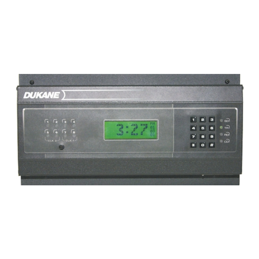
Holiday schedules Communications when using the master clock with an RS-485 network, modem • access, or the optional MasterLink programming software (available from Lathem) Parts List Verify that the master clock came with these parts: Master clock (ready to surface mount) •... -
Page 16: Mounting The Master Clock
19-inch (48.3 cm) rack. See Figure 1-1 for wall mount assembly parts. The display unit can also be hung on the wall with the power supply hidden in the floor or ceiling; contact Lathem for details. -
Page 17: Surface Mounting
Surface Mounting To surface mount the master clock: 1. Place the master clock on its back with the display unit facing up and the key pad to the right. 2. Remove the two screws at the top of the display unit mounting plate. 3. -
Page 18: Semi-Flush Mounting
Semi-Flush Mounting The power supply portion of the master clock can be recessed into the wall, so that the display unit is semi-flush with the wall. This should only be done by a qualified technician. To mount the master clock semi-flush: 1. -
Page 19: Using The Installer's Hooks To Hang The Display Below The Backbox
Using the Installer’s Hooks to Hang the Display Below the Backbox When mounting the clock in either semi-flush or surface installations, the hooks on the back of the display unit mounting plate can be used to hang the display unit below the backbox to allow access for circuit testing and programming. -
Page 20: Rack Mounting
Rack Mounting The two L-shaped brackets and the box cover supplied with the master clock can be used to install it in a standard 19-inch (48.3 cm) rack. See Figure 1-3 on page 1-7. To rack mount the clock: 1. Place the master clock on its back with the display unit facing up and the key pad to the right. -
Page 21: L Brackets For Rack Mounting
L Bracket Rectangular Knock Out L Bracket Figure 1-3 L Brackets for Rack Mounting 24A715/24A715M Master Clock Installation Manual... -
Page 22: Wiring The Master Clock
Wiring the Master Clock This section provides instructions on wiring the power source, secondary clocks, and sig- naling devices to the master clock. It does not cover the connection of the optional modem, a computer, any RS-485 devices, and a power source for the optional remove schedule selector. -
Page 23: Master Clock Terminal Blocks
1. Wire the power source to P4 as shown in either Figure C-1 or C-2 on page C-2. Note: The master clock is shipped set up for 120Vac operation. To wire it for 220/240Vac, change the jumper settings as shown in Figure C-2. 24A715/24A715M Master Clock Installation Manual Figure 1-5 Master Clock Terminal Blocks... -
Page 24: Synchronizing Non-Compatible Clocks By External Pulse
The master clock can synchronize to other systems if necessary. For example, you have a non-compatible time clock that cannot be synchronized by the master clock, but it has a built-in bell ringer. By shorting terminals 7 and 8 on terminal block P4, or terminals 6 and 7 of the communications terminal on the back of the display unit, the master clock will immediately reset to 00:00 (midnight). -
Page 25: Setting Up The Master Clock
Setting Up the Master Clock Once the master clock is installed, it is ready for programming. This chapter covers the programming instructions needed to set the master clock for operations. Note: To completely clear the clock of all settings and reset the master clock to its factory- shipped configuration, press the following number sequence on the master clock key pad: 355379768274. -
Page 26: Programming Functions
Programming Functions This section explains how to put the master clock in program mode and configure the necessary functions to get the master clock running. For definitions of all functions, key pad commands, and the bell test, see Section 3—Function List. The master clock is normally in clock mode, displaying the date and time. -
Page 27: Setting The Date And Time
Setting the Date and Time Use the [1]=SET DATE / TIME function to set the date and time. Enter the user password as shown on page 2-2, then follow the key sequences below: Press [0]...[8] [1]...[7] [0]...[8] [0] or [1] 24A715/24A715M Master Clock Installation Manual Display SELECT FUNCTION CODE... -
Page 28: Enabling The Relays
Enabling the Relays Use the [6]=ENABLE CIRCUITS function to enable or disable the master clock’s con- trol relays during circuit wiring or maintenance. This function can also hold back clocks to manually adjust for daylight saving time in the fall if the daylight saving function is not in use (see Setting Daylight Saving Time on page 2-7). -
Page 29: Choosing The Clock Types To Synchronize
Choosing the Clock Types to Synchronize To select a clock type for the master clock to synchronize, use the [2]=SELECT CLOCK CTL function. This allows you to match the master clock to the type of secondary clocks installed. This function configures both clock #1 (relays 7 and 8) and clock #2 (relays 5 and 6), if present. -
Page 30: Manually Activating Bell Controls
Manually Activating Bell Controls Use the [3]=MANUAL BELL CTRL function to test the bell circuits. This function does not require a password. Follow the key sequences below: Press [1]...[8] Display SELECT FUNCTION CODE [3]=MANUAL BELL CTRL MANUAL BELL CONTROLS 1-2-3-4-5-6-7-8 PRESS AND HOLD [#] TO EXECUTE. -
Page 31: Testing The Bells
If your nation does not appear in the country code list, or if the dates for daylight sav- ing in your country have changed, choose code 00 and use the optional Lathem MasterLink software to program clock adjustments. If your region does not observe daylight saving time, choose code 00. -
Page 32: Setting Communications
ID number. Use this function if the clock will be programmed to call the NIST atomic clock, or if you are using the optional Lathem MasterLink software to program the master clock. The clock can be set up using RS-232 (serial), RS-485 (networked), or modem (remote) com- munications. -
Page 33: Securing The Setup
Securing the Setup At this point you have finished the basic setup of the master clock and it should be up and running. The clock can now be programmed with user-specific settings such as bell schedules and holidays. For detailed information, see the Master Clock User Guide, doc- ument 427-07-00047. - Page 34 Notes 2-10 24A715/24A715M Master Clock Installation Manual...
-
Page 35: Section 3-Function List
Introduction This chapter list all functions accessible through the master clock key pad. For detailed instructions on these functions, see Section 2—Configuration and the Master Clock User Guide, document 427-07-00047. Quick Commands Quick commands are used to display system information for about two seconds. You can press the quick keys, [*], [1], or [3], when the master is displaying the time and date. -
Page 36: View Edit Keys
[1] VIEW EDIT KEYS Any time the master clock is in clock mode (displaying time and date), press [1] to see the edit key designations. See Figure 3-2 and Table 3-2. The edit keys are used when programming bell schedules, automatic schedule change dates, and holiday dates. Quick command [1] only displays a listing of the edit keys for reference;... -
Page 37: Programming Commands
Programming Commands To access the master clock’s programming functions, press [#] to enter program mode. When SELECT FUNCTION CODE appears on the display, the clock is ready for programming. The master clock will automatically exit out of program mode if you have not made a key pad entry for five minutes. -
Page 38: Manual Bell Ctrl
[3]=MANUAL BELL CTRL This function does not require a password. Use this function to test bell circuits or to manually ring a bell at an unscheduled time. See Manually Activating Bell Controls on page 2-6. [4]=PROGRAM SCHEDULE Use this function to set bell schedules. Bell schedules are defined as the days and times when the bell circuits will turn on. -
Page 39: Daylight Savings
[7]=DAYLIGHT SAVINGS This function requires the administrative password. Programming the master clock with the appropriate two-digit country code enables it to automatically adjust for daylight sav- ing time. See Appendix A for the country code list, and see Setting Daylight Saving Time on page 2-7. -
Page 40: [B]=Communications
[B]=COMMUNICATIONS This function requires the administrative password. Use this function to set the master clock’s terminal ID# and baud rate. See Setting Communications on page 2-8. [C]=CHANGE PASSWORD Use this function to change the default user password (000000) to another six-digit num- ber to prevent unauthorized access to the master clock’s programming functions. -
Page 41: Appendix A-Daylight Saving Country Codes
DAYLIGHT SAVING COUNTRY CODES ALBANIA ANDORRA ARMENIA AUSTRIA AZERBJAN AZORES BAHAMAS BALEARIC ISLANDS BELARUS BELGIUM BERMUDA BOSNIA/HERZEGOVINA BRAZIL BULGARIA CANADA CHANNEL ISLANDS CHILE CROATIA CUBA CYPRUS CZECH REP DENMARK EASTER ISLAND EGYPT 24A715/24A715M Master Clock Installation Manual Daylight Saving Country Codes ENGLAND ESTONIA FALKLAND ISLANDS... -
Page 42: Daylight Saving Time Codes And Duration
DAYLIGHT SAVING TIME CODES AND DURATION Code Start and end date Last Sunday in March, 3rd Sunday in October Last Sunday in March, last Sunday in September First day of April, last day of September First Friday in April, 1st Sunday in September First Friday in April, 3rd Friday in September First Sunday in April, 1st Saturday in October First Sunday in April, last Sunday in October... -
Page 43: Appendix B-Secondary Clock Types
Simplex 77 Series Simplex 93-9 Simplex 91-9 Simplex 941-9 Simplex 943-9 Standard Electric D10, D12 Stromberg 3000 Three-Wire Minute Impulse/59 Lathem ISC Two- and Three-Wire Cincinnati D2-D4 Dukane 24ISC Series Edwards Impulse Faraday Impulse IBM 75 Series Simplex 75 Series Simplex 91-4... -
Page 44: Wiring Secondary Clocks
Wiring Secondary Clocks The next several pages contain wiring diagrams and theory of operation for the secondary clocks. These are listed in numerical order according to type code number. Note: All circuits should be fused or protected by a circuit breaker (10A maximum). The 24A715 and 24A715M master clocks are factory-equipped to operate analog clocks on the CLK1 output (relays 7 and 8), and CLK2 output (relays 5 and 6). -
Page 45: Three-Wire Synchronous (59Th Minute, Dukane 24Ss
Please note that the relay contacts used in the CLK2 circuit are rated at 10 amps. The combined load of the correction circuit and the run circuit should not exceed 8 amps. In general, 20–35 analog clocks can be operated on a single string. This number depends on the clock style and the distances involved. -
Page 46: Type 02-Three-Wire Minute Impulse (59Th Minute
TYPE 02—Three-Wire Minute Impulse (59th Minute) There are two types of Type 02 secondary clocks: the three-wire minute impulse covered on this page, and the two-wire reverse polarity minute impulse on the following page. Note: For a list of Type 02 clocks, see the chart on the first page of this appendix. From the 58th second to 00 seconds each minute, a 24Vdc pulse is transmitted to the sec- ondary clocks. -
Page 47: Type 02-Two-Wire Reverse Polarity Minute Impulse (59Th Minute
TYPE 02—Two-Wire Reverse Polarity Minute Impulse (59th Minute) There are two kinds of Type 02 secondary clocks: the two-wire reverse polarity minute im- pulse covered on this page, and the three-wire minute impulse on the previous page. Note: For a list of Type 02 clocks, see the chart on the first page of this appendix. Every minute, from the 58th second to 00 seconds, a 24Vdc pulse is transmitted to the secondary clocks. -
Page 48: Type 03-Standard Electric Synchronous
TYPE 03—Standard Electric Synchronous During normal operation, 120Vac is applied to the run motor. A 15-minute correction signal on the correction motor line causes a 12-hour correction from 5:12:00 to 5:28:00. This occurs twice daily (AM and PM). Run motor power is connected during the 12-hour correction. -
Page 49: Type 04-Standard Electric Time Ar-2A Two-Wire, Dual Voltage
TYPE 04—Standard Electric Time AR-2A Two-Wire, Dual Voltage Each minute, from 58 seconds to 00 seconds, a low-voltage pulse (24Vdc) is transmitted. The secondary clocks receive the pulses until the 59th minute. At this time, from 50 sec- onds to 00 seconds, a higher voltage pulse (48Vdc) is required to advance to the hour. Manual clock advances and daylight saving advances cause the master clock to transmit 62 pulses (one second ON and one second OFF at 0.5Hz), all at 24Vdc. -
Page 50: Type 05-Three-Wire Minute Impulse (58Th Minute
TYPE 05—Three-Wire Minute Impulse (58th Minute) Each minute, from the 58th second to 00 seconds, a 24Vdc pulse is transmitted to the sec- ondary clocks. From the 58th minute through the 48th minute, the pulse is transmitted on both the A and B lines. From the 49th minute to the 58th minute, the pulse is transmitted on the A line only. -
Page 51: Type 06-Synchronous Wired
TYPE 06—Synchronous Wired For a list of Type 06 clocks, see the chart on the first page of this appendix. The clock run motor receives 120Vac continuously, with 120Vac furnished to the clock correction coil for 55 seconds each hour from HH:58:05 to HH:59:00 to cause hourly corrections. -
Page 52: Type 07-Dukane Digital Clocks
TYPE 07—Dukane Digital Clocks For a list of Type 07 clocks, see the chart on the first page of this appendix. Notes: Dukane Model 24D20 and 24D40 are only used with 15Vdc power when being added to existing installations. In new installations, these two models should be used with 24Vac power. -
Page 53: Wiring Dukane 24F200, 24F750, And 24F750A Digital Clocks For 15Vdc
X = Normally open contact = To obtain the solid state relay, order Dukane Model 438-860 RELAY CLK1 MASTER CLOCK FIELD CONNECTIONS 15Vdc – Wiring Dukane 24F200, 24F750, and 24F750A Digital Clocks for 15Vdc X = Normally open contact = To obtain the solid state relay, order Dukane Model 438-860 RELAY CLK1 MASTER CLOCK... -
Page 54: Type 08-Rauland 2410 Digital Clocks (24Vac And 120Vac
TYPE 08—Rauland 2410 Digital Clocks (24Vac and 120Vac) Rauland 24Vac or 120Vac digital clocks initialize to 12:01 AM when first powered up. During normal operation, the clocks maintain time by counting the 60Hz AC line frequency. When the line voltage drops below 120Vac, the digital clocks start rapidly advancing at two minutes per second. -
Page 55: Wiring Rauland 2410 Digital Clocks For 120Vac
X = Normally open contact I = Normally closed contact 1 = V250LA4 MOV or equal CLK2 MASTER CLOCK FIELD CONNECTIONS 120Vac 65–85Vac AC RTN X = Normally open contact I = Normally closed contact 1 = V250LA4 MOV or equal CLK2 MASTER CLOCK FIELD CONNECTIONS... -
Page 56: Type 09-Simplex 59Th Minute, Dual Motor
TYPE 09—Simplex 59th Minute, Dual Motor Power is normally applied to the 1 RPM run motor. Each hour, from HH:58:05 through HH:58:59, power is removed from the run motor and applied to the fast advance motor. During manual clock corrections, power is applied to both motors for 4 minutes and 15 seconds. -
Page 57: Type 11-Edwards Dual Motor
TYPE 11—Edwards Dual Motor Power is applied only through relay K6 to the run motor for normal timekeeping. During power interruptions (while clocks are stopped) and during correction, the master clock accumulates the number of seconds. Immediately after power is restored, both relays K6 and K5 operate. -
Page 58: Type 12-Cincinnati D6 Clocks
TYPE 12—Cincinnati D6 Clocks Normal pulsing is sent out on lines A and C from second 58 through second 00 each minute. From minute 59 through minute 49, line A is positive with respect to line C. From minute 50 through minute 58, except from 4:49 through 5:55 AM and PM, line C is positive with respect to line A. -
Page 59: Type 13-Two-Wire Pulse Alternating (24Vdc
TYPE 13—Two-Wire Pulse Alternating (24Vdc) Every minute from 59 seconds to 00 seconds, a 24Vdc signal is applied on lines A and B, causing the clocks to advance one minute. The polarity of the pulse is alternated each minute to cause A to be positive with respect to B one minute, then B positive with re- spect to A the next minute, and so on. -
Page 60: Type 14-Electronic Coded Clocks
TYPE 14—Electronic Coded Clocks Clocks normally run with 120Vac power. For bells or clock correction, the generator prestart relay (K6) first turns on for the signal generator to reach frequency. K6 turns on at the 00 second after a programmed time or manual bell time. Then relay K5 turns on for three seconds, from the 10th to the 13th second, to apply the generator signal (coded cup start signal) onto the 120Vac. -
Page 61: Electronic Coded Clocks
X = Normally open contact I = Normally closed contact 1 = V250LA4 MOV or equal RELAY K6 (K8) CLK1 OR CLK2 10 ASB MAX. 120Vac AC RTN 24A715/24A715M Master Clock Installation Manual RELAY K5 (K7) MASTER CLOCK FIELD CONNECTIONS Figure B-16 Electronic Coded Clocks START SIGNAL... -
Page 62: Type 15-Straight Frequency
TYPE 15—Straight Frequency Clock correction and bell circuit operations are generated by sequentially applying vari- ous frequencies onto the 120Vac. Each bell and clock correction circuit has its own frequency and a receiver circuit that applies the associated bell or clock frequency (3,510Hz normally used for clock signals). -
Page 63: Type 16-Three-Wire Minute Impulse (59Th Minute) With 12-Hour Correction
TYPE 16—Three-Wire Minute Impulse (59th Minute) with 12-Hour Correction There are two types of type 16 secondary clocks: the three-wire minute impulse covered on this page, and the two-wire reverse polarity minute impulse on the following page. Each hour from the 59th minute through the 49th minute, a two-second pulse is transmit- ted on both the A and B lines, starting at the 58th second and ending at 00 seconds, causing all clocks to advance each minute. -
Page 64: Type 16-Two-Wire Reverse Polarity Minute Impulse (59Th Minute) With 12-Hour Correction
TYPE 16—Two-Wire Reverse Polarity Minute Impulse (59th Minute) with 12-Hour Correction There are two types of type 16 secondary clocks: the two-wire reverse polarity minute impulse covered on this page, and the three-wire minute impulse on the previous page. Each hour, from the 59th minute through the 49th minute, a two-second pulse is transmit- ted between lines AB and PC (with AB positive with respect to PC), starting at the 58th second and ending at 00 second. -
Page 65: Type 17-Standard Electric Time Ar-3 Three-Wire Impulse
TYPE 17—Standard Electric Time AR-3 Three-Wire Impulse Each minute from 58 seconds to 00 seconds, a pulse is transmitted on line. The secondary clocks receive the pulses on line A until the 58th minute. At this time, from 50 seconds to 00 seconds, a pulse on line B is required to advance to the 59th minute. -
Page 66: Type 18-National Synchronous Wired
TYPE 18—National Synchronous Wired For a list of Type 18 clocks, see the chart on the first page of this appendix. Relay K5 is normally operated to power the clock run motors. Each hour from HH:00:00 to HH:00:28, relay K6 is operated to power the clock correction coils for 28 seconds and cause hourly corrections. -
Page 67: Type 19-Stromberg Synchronous Wired (56Th Minute
K5 is deactivated. Note: Lathem SS Modified wall clocks operate according to the above signal operation if modified to reference the minute and second hands to HH:57:16 (versus HH:59:00) and the hour hand to 12:00 (versus 6:00). -
Page 68: Type 20-Three-Wire Minute Impulse (44Th Minute
TYPE 20—Three-Wire Minute Impulse (44th Minute) Every minute, from the 58th second to 00 seconds, a 24Vdc pulse is transmitted to the secondary clocks. From the 44th minute through the 34th minute, the pulse is transmitted on the A and B lines. From the 35th minute to the 44th minute, the pulse is transmitted on the A line only. -
Page 69: B-24 Cincinnati D1
TYPE 21—Cincinnati D1 Every minute, from HH:MM:58 to HH:MM:00, relay K6 is activated, causing an output on line A for two seconds. During minutes 07 through 58 only relay K6 activates, causing the output on line A to be 24Vdc. During minutes 59 through 06, relay K5 is also activated, together with relay K6, causing the output on line A to be 60Vdc to advance all clocks. -
Page 70: Type 22-Dukane Synchronous Wired (24A Series, Obsolete
TYPE 22—Dukane Synchronous Wired (24A Series, Obsolete) During normal operation, either 24Vac or 120Vac is furnished to the clock run motor through relay K6. Power is removed from the run motor during power failures, while K6 de-energizes during fall daylight saving changes. Each hour from HH:57:00 to HH:57:55, relay K5 energizes to furnish a 24Vdc signal to the correction coil. -
Page 71: Type 23-Condor Digital Clocks (Model 2412
TYPE 23—Condor Digital Clocks (Model 2412) For a list of Type 23 clocks, see the chart on the first page of this appendix. Condor digital clocks initialize to 12:00 AM when power is first applied. During normal operations, the clocks maintain time by counting the 60Hz AC line frequency. When the line voltage drops to approximately two-thirds normal level, the clocks start rapidly ad- vancing at a rate of two minutes per second. -
Page 72: Type 24-Edwards Synchronous Wired Clocks, Type E1
TYPE 24—Edwards Synchronous Wired Clocks, Type E1 During normal operation, 120Vac is applied between the run motor and common lines to operate the clocks until the 58th minute. At HH:58:00 of each hour, the 120Vac is re- placed by 120Vdc between the correction and common lines for a period of 200ms, with the common line being positive. -
Page 73: Type 27-Simplex 2310 Dual Motor
120Vac AC RTN Types 28, 29, and 30 For wiring information on Type 28 (Stromberg 12-hour), Type 29 (Type 01 Special), and Type 30 (Type 14 Special) clocks, contact Lathem Time Corporation. 24A715/24A715M Master Clock Installation Manual RELAY RELAY K5 (K7) K6 (K8) 10 ASB MAX. - Page 74 Notes B-32 24A715/24A715M Master Clock Installation Manual...
-
Page 75: Wiring Diagrams List
Wiring Diagrams List This appendix contains wiring information and diagrams for the installation of the Dukane 24A715/M Master Clock: C-1 Wiring the 24A715/M for 120Vac Operation......... . . C-2 C-2 Wiring the 24A715/M for 220/240Vac Operation . -
Page 76: Wiring The Master Clock For 120Vac Or 220/240Vac
Wiring the Master Clock for 120Vac or 220/240Vac The master clock is factory-shipped ready for 120Vac. Figure C-1 shows the correct wir- ing for 120Vac operation. Figure C-2 shows the correct wiring and adjusted jumper settings for 220 and 240Vac operation. All circuits should be fused or protected by a circuit breaker (10-amp maximum). -
Page 77: Wiring Signal Devices To The Master Clock
Wiring Signal Devices to the Master Clock Typically, signal devices (such as bells or lights) are wired to terminal block P3. If no secondary clocks are connected to terminal blocks P1 or P2, signal devices can also be wired to those blocks. See the figures below. Zone 7A and 7B operate together, and 5A and 5B operate together. -
Page 78: Wiring The Communications Terminal Block
The host communications terminals on the communications terminal block include: RS-232—Three terminal block contacts for RS-232 communications with an IBM- compatible computer running the optional Lathem MasterLink programming software. Notes: This terminal is typically used for a permanent connection to a computer. To make a cable to connect the computer to the RS-232 terminals, see Figure C-7 on page C-5. -
Page 79: Wiring The Ddc4R Communications Terminals
RS-485—Terminal block pair for RS-485 communications with an IBM-compatible computer running the optional Lathem MasterLink programming software and SWIFT (RS-485 to RS-232 converter). MODEM—Modular connector for modem use. The optional internal modem can be used to dial out to the Atomic Clock at Fort Collins, Colorado, USA, or for a remote site using the optional Lathem MasterLink programming software. -
Page 80: Wiring Rs-485 Time Synchronization Devices
Wiring RS-485 Time Synchronization Devices Up to 30 RS-485 Data Synchronization Devices (DSDs) can be connected to the sync ter- minals. Since the SYNC IN port can send as well as receive, 30 extra devices can be connected. If more than 60 DSDs are to be connected, another master clock must be used as a booster. -
Page 81: Wiring The 12 Volt Ac Out Terminals
The 12 Volt AC Out Terminals connect to a non-regulated 12V 250mA power source and are used with the optional remote schedule selector (available from Lathem) when in close proximity to the master clock. Contact Lathem Time Corporation for details. -
Page 82: Connecting A Computer To The Front Access Port
Connecting a Computer to the Front Access Port A computer can be temporarily connected to the master clock via the front access port. See the figure below to make a cable for this purpose. Figure C-11 Computer Cable for Front Access Port 24A715/24A715M Master Clock Installation Manual... -
Page 83: Power Supply Schematic
Appendix Power Supply Schematic Figure D-1 Power Supply Schematic for the 24A715/M Master Clock 24A715/24A715M Master Clock Installation Manual... - Page 84 Notes 24A715/24A715M Master Clock Installation Manual...
- Page 86 DUKANE CORPORATION COMMUNICATIONS SYSTEMS DIVISION - 2900 Dukane Drive, St. Charles, Illinois 60174 © 2001. Printed in USA. All specifications subject to change without notice.
Need help?
Do you have a question about the Dukane 24A715M and is the answer not in the manual?
Questions and answers
Tenemos problemas para sincronizar los relojes secundarios DUKANE, seguimos los pasos como se indica en el manual y el reloj maestro si responde pero los relojes secundarios marcan horarios defierentes.
To synchronize Dukane 24A715M secondary clocks when they show different times, follow these steps:
1. The master clock sends an 8-second correction pulse from 57:54 to 58:02 every hour. This advances the minute hand of secondary clocks to the correct time.
2. If the secondary clocks are more than one hour off, the master clock sends a 6-second absolute correction pulse at 5:58:02 (AM and PM). This advances clocks toward 5:58:00.
3. Clocks up to 11 hours behind are corrected to 5:58:00 after one 12-hour correction cycle. Clocks more than 11 hours behind need two cycles.
4. After reaching 5:58:00, the clocks synchronize fully at 6:58:00.
The correction process may take hours depending on the time difference.
This answer is automatically generated