Table of Contents
Advertisement
Quick Links
Advertisement
Table of Contents

Related Manuals for Roda RK786EX

Summary of Contents for Roda RK786EX
- Page 1 NOTEBOOK COMPUTER RK786EX USER’S GUIDE...
- Page 2 Copyright © 2004 All rights reserved. No part of this publication may be reproduced, transmitted, transcribed, stored in a retrieval system, or translated into any language, or computer language, in any form, or by any means, electronic, mechanical, magnetic, optical, chemical, or other, without the prior written permission of the manufacturer.
-
Page 3: Federal Communications Commission Statement
EMC and Safety Notice Federal Communications Commission Statement This equipment has been tested and found to comply with the limits for a class B digital device, pursuant to part 15 of the FCC Rules. These limits are designed to provide reasonable protection against harmful interference in a residential installation. - Page 4 SAR Exposure This device has been tested for compliance with FCC RF Exposure (SAR) limits in typical flat configurations. Products with the CE Marking comply with both the EMC Directive (89/336/EEC) and the Low Voltage Directive (73/23/EEC) issued by the Commission of the European Community.
- Page 5 Is herewith confirmed to comply with the requirements set out in the Council Directive on the Approximation of the Laws of the Member States relating to Electromagnetic Compatibility (89/336/EEC), Low- voltage Directive (73/23/EEC) and the Amendment Directive (93/68/EEC), the procedures given in European Council Directive 99/5/EC and 89/3360EEC.
-
Page 6: Power Conservation
Power Conservation This computer consumes much less power than conventional computers; however, power consumption may be reduced by properly configuring the Power Management Setups. It is recommended that the power saving functions be enabled even when not running on battery power. Power Management generally does not degrade system performance while saving power. -
Page 7: Table Of Contents
CONTENTS GETTING STARTED ..................1 ......................1 NPACKING ....................2 UICK PERATION ................3 ONTROLS AND NDICATORS USEFUL INFORMATION .................. 7 ......................7 OCATION ......................7 UGGEDNESS ................... 8 PERATING YSTEMS AC A ......................8 DAPTER ......................9 ATTERY POST ..................10 P AND ................ - Page 8 PCMCIA C ....................21 OVER ..................... 21 EHICLE DAPTER ................. 21 ATTERY HARGER ....................... 21 OCKUNDER SPECIFICATIONS..................... 23 CPU ........................23 ......................23 EMORY ......................23 ISPLAY ......................23 EYBOARD ................... 24 LOPPY RIVE ....................24 RIVE CD-ROM D ....................24 RIVE ....................
- Page 9 ....................37 UDIO RIVER LAN C .................... 37 RIVER ................37 ODEM RIVER MAINTENANCE / SERVICE ................38 ......................38 LEANING .................... 38 ROUBLESHOOTING RMA S ....................38 ERVICE...
-
Page 10: Getting Started
Getting Started GETTING STARTED Unpacking The following components come with your computer. If anything is missing or damaged please notify the dealer immediately. Computer unit • Removable FDD or CD-ROM (one of them is installed on computer and • the other as accessory) AC Adapter •... -
Page 11: Quick Operation
Getting Started Quick Operation • Loosen the battery screw, remove the battery insulation sheet, and then re-position the battery for operation. • Attach the AC adapter and charge battery for at least 10 minutes. • Turn ON the computer by pressing the power switch momentarily. •... -
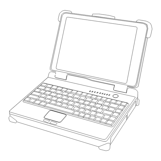
Page 12: Controls And Indicators
Getting Started Controls and Indicators Controls and Indicators (Upper) 1. (Reserved) 2. PCMCIA 3. Keyboard Number Lock 4. Keyboard Caps Lock 5. Keyboard Scroll Lock 6. HDD in use 7. Secondary Battery Charge 8. Primary Battery Charge 9. Power indicator 10. - Page 13 Getting Started 12. Touch pad 13. Touch pad right button Controls and Indicators (Right) FDD Configuration: 1. FDD in use 2. Diskette eject button CD-ROM Drive Configuration: 1. CD-ROM eject button 2. CD-ROM in use Battery Configuration: (optional) No special control or indicator.
- Page 14 Getting Started eft) Controls and Indicators (L 1. External Keyboard + PS/2 port 2. LAN Jack 3. IEEE1394 port (Fire Wire) 4. IEEE1394 port 5. USB port (Universal Serial Bus) 6. USB port (Universal Serial Bus) 7. 2 PCMCIA Slots 8.
- Page 15 Getting Started Controls and Indicators (Rear) 1. Optional Military connector port 2. Optional Military connector port 3. DC Power Jack 4. External DVI port 5. External RGB Monitor Port 6. Printer/External FDD Port* 7. Docking Port 8. Serial Port COM2 9.
-
Page 16: Useful Information
Useful Information USEFUL INFORMATION Location A clean and moisture-free environment is preferred. Make room for air circulation. Avoid areas with: • Sudden or extreme changes in temperature. • Extreme heat. • Strong electromagnetic fields (near television set, motor rotation area, etc.). •... -
Page 17: Operating Systems
Useful Information Operating Systems The computer is compatible with most operating systems (OS). However, not all functions are 100% compatible. For example, ACPI, APM, Smart Battery, etc. are not available on DOS, Windows NT, and other non-Microsoft OS. Consequently “Standby”, “Hibernation”, “Battery Gauge”... -
Page 18: Battery
Useful Information AC Adapter Indicator The green LED indicates that the AC power is ready. Battery The computer will automatically switch to battery power when the external power source (AC adapter or optional vehicle adapter) is disconnected. Battery Power Saving Tips The computer comes with an intelligent power-saving feature. -
Page 19: Boot Up And Post
Useful Information Note: Battery characteristic varies depending on factors such as ambient temperature, charging method, load current, aging, etc. For example, at low temperature the chemicals of the battery are more inactive, thus decreases the output power. The battery gauge should only be used as a reference. Please do not expect it to show the exact amount of the power remaining. -
Page 20: Standby/Hibernate/Resume
Useful Information The ROM BIOS Power On Self-Test (POST) Each time the computer powers on, it automatically performs a self-test of its memory and hardware devices. Standby/Hibernate/Resume The system can enter standby or hibernate mode by either pressing the power switch or staying idle till timeout. - Page 21 Useful Information To remove the modules: 1. Turn OFF the computer or hibernate. 2. Disconnect all cables from the computer. 3. Use a coin to turn and loose the screws on the modules. 4. Remove the battery from the compartment. 5.
-
Page 22: Components And Functions
Components and Functions COMPONENTS AND FUNCTIONS Keyboard The keyboard is functionally equivalent to a full size desktop keyboard. A sample key layout is shown below. The Numeric Keypad The numeric keypad functions like an electronic calculator. It is embedded in the main keyboard, with the numeric figures printed on the upper right of their respective keys. -
Page 23: Floppy Disk Drive
Components and Functions Keyboard Backlight (optional) Press [Fn] [F5] key for approximately 1 second turns keyboard backlight ON or OFF. Floppy Disk Drive The computer comes with a 3.5" 1.44MB floppy disk drive (FDD). The 1.44MB FDD can also read and write 720KB double side double density diskette. It is recommended that high density (2HD marking) diskette been used only. -
Page 24: Cd-Rom Drive
Components and Functions Note: NEVER drop your HDD, FDD, CD-ROM module or expose them to high temperature, high humidity, or any hazardous environment. NEVER try to disassemble the module. Static discharge may destroy your device and data. Always pick up the modules by touching the case only. - Page 25 Components and Functions Ports (horizontal version, ports on rear) 1. COM2 2. COM1 3. PS/2 4. USB #1 & #2 5. RGB 6. DVI 7. IEEE1344 #1 8. IEEE1394 #2 9. LAN 10. ANT. 11. DC jack Ports (vertical version, ports on bottom) 1.
- Page 26 Components and Functions 2. DVI 3. RGB 4. COM2 5. COM1 6. ANT. 7. PS/2 8. DC jack 9. USB Mount the Dockunder: 1. Turn OFF the power. 2. Open the rubber cap of the docking connector. 3. Align the docking connector. 4.
- Page 27 Components and Functions 5. Lock the computer. There is 2 PCI slots on the Dockunder. Maximum card dimensions are 260mm (L: length, including L-bracket thickness) x 115mm (W: width, including gold fingers) x 25 mm (H: height). The total power rating of 2 PCI slots is +5V 3A, +3.3V 3A, +12V 300mA, -12V 300mA.
- Page 28 Components and Functions Never dock or un-dock the computer while power is ON. Timer output 0 0 Sound 1 Sound 2 8 RTC 2 FDD 9 ACPI (or Free) 3 Reserved (or ECP/EPP) 10 Free (16-bit PCMCIA, or COM3*) 11 PCI devices or Card Bus 0/1 (Sound, LAN*, 32-bit PCMCIA, etc.) 12 Touch pad (PS/2 mouse) 13 Co-processor 14 HDD...
-
Page 29: Optional Devices
Optional Devices OPTIONAL DEVICES Memory Card The memory card will expand your memory to facilitate better system performance. The cards are available as following: 256MB, 512MB Battery A Lithium Ion rechargeable 2 battery may install into the CD-ROM/FDD compartment. It has the same capacity of primary battery and Smart Battery compliance. -
Page 30: Touch Screen
Optional Devices Touch Screen Resistive or capacitive touch screens for direct finger touch or pen input instead of mouse or touch pad. Note: Capacitive touch screen requires a “grounding” to work properly. Otherwise it will not activate when touched. Generally the grounding is sufficient if the AC adapter is attached or the computer/panel is mounted on a vehicle’s metal parts. - Page 31 Optional Devices Dockunder RT7-V: (no hot docking) 2 PCI slots, serial ports x 2, USB (v.2.0) x 2, 1394 x 1, PS/2, RGB. Ports are on the bottom. Dockunder RT7-V2: (hot docking) No PCI slots, serial ports x 2, USB (v.2.0) x 2, 1394 x 1, PS/2, RGB. Ports are on the bottom.
-
Page 32: Specifications
Specifications SPECIFICATIONS RK786EX: Intel Pentium M ( Dothan) CPU runs at multiple speeds dependent on CPU type and operating system: The CPU speed switches automatically by detecting AC adapter/battery operation and busy state. Memory Standard: 512MB System memory Expandable: 1GB... -
Page 33: Floppy Disk Drive
Specifications Function: Emulates standard 101/102-key keyboard Floppy Disk Drive Standard: Size: 3.5" Capacity: 1.44MB (formatted) Rotation: 300 RPM Transfer Rate: 500KB/sec Average Access: 94 ms (with settling) Hard Disk Drive Type: 2.5” Interface: IDE Ultra DMA 33 compliant CD-ROM Drive Speed: 24 x Interface:... -
Page 34: Ac Adapter
Specifications • External PS/2+Keyboard port • Audio ports (External Speaker/Earphone, Microphone, Line-in) • RJ11 Phone jack for internal Fax/Modem (optional) • RJ45 jack for internal LAN card (optional) • 2 type II or 1 type-III PCMCIA slots • Printer/External FDD port •... -
Page 35: Battery
Specifications Battery Primary Battery: Type: 9 x 18650 cells Lithium Ion Capacity: 11.1V 6000mAH Dimension: 103 mm(W) x 73 mm(D) x 38 mm(H) Weight: 435 g (0.95 1b.) Battery (optional): Type: 9 x 18650 cells Lithium Ion Capacity: 11.1V 6000mAH Dimension: 150 mm(W) x 90 mm(D) x 20 mm(H) Weight:... -
Page 36: Environmental
Specifications Packing: Carton: Unbleached paper Cushion: Recyclable EPE Carrying bag: Recyclable PE Fiber User's Guide: Recycled/Recyclable paper Please recycle the parts according to local regulations. Environmental Temperature: 0 ~ 45ºC (32 ~ 113ºF) operating -40 ~ 70ºC (-40 ~ 158ºF) storage Humidity: 5~95% Non-condensing operating 95% maximum storage... -
Page 37: Bios Setup
BIOS Setup BIOS SETUP Press [F2] at boot up to enter BIOS setup. Use arrow keys to select options and [+/-] to modify them. When finished, move to ”Exit” and press [Enter] then confirm save by pressing [Y]. Main Menu Phoenix BIOS Setup Utility Main Advanced... - Page 38 BIOS Setup Diskette 1 3 ½" 1.44MB, Select the type of floppy-disk Disabled drive installed in your system. 1.25 MB is a Japanese media format that requires a 3½" 3-Mode Diskette drive. System Memory Displays amount of conventional memory detected during boot up. Extended Memory Displays the amount of extended memory detected during boot up.
-
Page 39: Advanced Menu
BIOS Setup Advanced Menu Phoenix BIOS Setup Utility Main Advanced Security Power Boot Exit Item Specific Help Boot-time Diagnostic Screen: [Enabled] Summary Screen: [Disabled] Peripheral Legacy USB Support: [Enabled] Configuration for POST Memory Test: [Quick Test] BootUp Display: [CRT+LCD] COM port Parallel port I/O Device Configuration F1 Help... -
Page 40: Security Menu
BIOS Setup Parallel Port: [Enabled] Mode: [Output Only] Base I/O address: [378] Interrupt [IRQ 7] F1 Help Select Item Change Values F9 Setup Defaults ↑↓ Esc Exit Select Menu Enter Select Sub-Menu F10 Save and Exit ← ► I/O Device Configuration Sub-menu Selections Please refer the on screen help for selections. - Page 41 BIOS Setup Security Menu Selections Feature Options Description Set User Password Up to seven Pressing <Enter> displays the alphanumeric dialog box for entering the user characters password. In related systems, this password gives restricted access to SETUP menus. Set Supervisor Up to seven Pressing <Enter>...
-
Page 42: Power Menu
BIOS Setup Power Menu Phoenix BIOS Setup Utility Main Advanced Security Power Boot Exit Item Specific Help Power Button Function: [Power Off] Select LID close function Lid Close Function: [LCD Off] Sleep Button Function: [Stand By] as LCD Off or Standby Speed Step Technology: [GV3] function... -
Page 43: Exit Menu
BIOS Setup Exit Menu Phoenix BIOS Setup Utility Main Advanced Security Power Boot Exit Item Specific Help Exit Saving Changes Exit Discarding Changes Load Setup Defaults Exit System Setup and Discard Changes save your changes to Save Changes CMOS. F1 Help ↑↓... -
Page 44: Utilities And Drivers
Check Read first file on utility CD to get the newest information before starting to install drivers. Chipset Windows WINXP/WIN2000/WIN98SE/ME Driver Installation: Insert the Driver CD into the CD-ROM. Click infinst_enu in RK786EX Driver \Chipset then follow the prompt to complete installation. VGA Utility Display Capability Resolution &... -
Page 45: Usb 2.0
The Windows XP with the service pack 1 is not necessary to install the driver. For RK786EX only Win98SE needs to install USB2.0 driver. Touch Screen Driver Enter BIOS Setup and set COM1 port as “TTL1”. (COM1 has multiple connectivity so it’s necessary to setup. -
Page 46: Cd-Rom Driver
CD from Control panel\System\Device Manager\PCMCIA Socket\Generic CardBus Audio Driver Windows 98SE/2000/ME/XP Insert the Driver CD into the CD-ROM. Click Setup in RK786EX \Driver \Audio \winxp2k98 then follow the prompt to complete installation. LAN Card Driver In Windows 98se/2000/ME/XP click System → Hardware → Device Manager →... -
Page 47: Troubleshooting
Maintenance/Service MAINTENANCE / SERVICE Cleaning ALWAYS turn OFF the power, unplug the power cord and remove the battery before cleaning. The exterior of the system and display may be wiped with a clean, soft, and lint- free cloth. If there is difficulty removing dirt, apply non-ammonia, non-alcohol based glass cleaner to the cloth and wipe. - Page 48 Maintenance/Service 3. If the original packing materials are not available, wrap the equipment with soft material (e.g., PU/ PE form) then put the wrapped equipment into a hard cardboard shipping box. 4. Include a sheet with the following information: (Note: please keep a copy of this sheet for your records) Name •...
- Page 49 Recycled / Recycleable Printed in Taiwan P/N:63070000...
Need help?
Do you have a question about the RK786EX and is the answer not in the manual?
Questions and answers