
Related Manuals for Tailift TPR720A

Summary of Contents for Tailift TPR720A
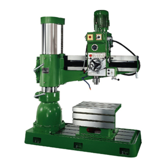
- Page 1 RADIAL DRILLS TPR720A TPR820A TPR920A TPR1100 Operation Manual D E C 0 0 2 / 0 4 TAILIFT LTD. 2006...
-
Page 2: Chapter 1 Safety Guidelines
CHAPTR 1 Safety Guidelines 1.1 Please follow the below basic safety principles﹕ ﹕ ﹕ ﹕ (1) Have only sophisticated or experienced personal perform the machine operation or maintenance. (2) Please read and understand the operation manual thoroughly before operation. (3) Please place the manual close to the machine for easy access. (4) Please have only authorized person keep the keys to the machine. -
Page 3: Precautions For Operation
Power-on is needed in it (3) Please power off after work. (4) Adding or replacing hydraulic oil or lubricant, Please use Tailift recommended oil type or its equivalent. For details, please refer to the chapter 7. (5) Basically, only one person is needed to serve. If more than one person is called for, Good communications is required. -
Page 4: Warning Labels And Mark On The Machine
1.5 Warning labels and mark on the machine 1.5.1 Warning labels and mark introduction labels Description Please secure the machine with the base fixing bolts, to prevent from any risk. 台勵福股份有限公司 Model of a machine. 台品工業股份有限公司 TA I PIN INDUSTRIAL CO ., LTD 機型號碼... - Page 5 1.5.2 Warning Labels and mark positions a. The front view. 台勵福股份有限公司 台品工業股份有限公司 TA I PIN INDUSTR IA L CO ., L TD 機型號碼 機型號碼 機型號碼 機型號碼 MODEL NO. MODEL NO. MODEL NO. MODEL NO. 製造號碼 製造號碼 製造號碼 製造號碼 SERIAL NO. SERIAL NO.
- Page 6 b-2. The rear view (only for TPR-1100) C. Oil filler position and Oil Drain outlet position Gearbox...
- Page 7 Arm elevating motor (For TPR-720A, TPR-820A, TPR-920A) Arm elevating motor (For TPR-1100)
-
Page 8: Chapter 2 General Specifications
CHAPTER 2 General Specifications 2.1 The anticipated machine life. The calculation of the anticipated machine life: 8 hours x 6 days x 50 weeks x 10 years = 24000 hours. The above calculation is based on a sound maintenance and normal condition, excluding wearing parts. -
Page 9: The Machine
It knows radial drills certainly very well. Tailift radial drills will be your best choice. T he material that the machine can process on are : mild steel, metal, stainless steel, cast iron, aluminum, copper,,,, etc, except magnesium alloy. -
Page 10: Only For Tpr-1100
Ⅱ Ⅱ Ⅱ Ⅱ . only for TPR-1100 There are six categories of parts on the radial drill: Gearbox, Arm, Column, Top Cover, Box Table and Base. The following are its description and locations. 1. Base The main aim of the base is to support the whole weight of the machine. -
Page 11: Tpr-720A
2.4 Specifications. 2.4.1 TPR-720A Specification. TPR-720A The Column diameter 210mm Distance from the column surface to the spindle center, 750mm Distance from the column surface to the spindle center, 220mm Horizontal travel of the Spindle head. 530mm Distance from the Base surface to the Spindle end, max. 1060mm Distance from the Base surface to the Spindle end, min. -
Page 12: Tpr-820A Specification
2.4.2 TPR-820A Specification. TPR-820A The Column diameter 210mm Distance from the column surface to the spindle center, max 850mm Distance from the column surface to the spindle center, min 220mm Horizontal travel of the Spindle head. 630mm Distance from the Base surface to the Spindle end, max. 1210mm Distance from the Base surface to the Spindle end, min. -
Page 13: Tpr-920A Specification
2.4.3 TPR-920A specification. TPR-920A The Column diameter 210mm Distance from the Column surface to the Spindle center, max. 950mm Distance from the Column surface to the Spindle center, min. 220mm Horizontal travel of the Spindle head. 730mm Distance from the Base surface to the Spindle end, max. 1210mm Distance from the Base surface to the Spindle end, min. -
Page 14: Tpr-1100 Specification
2.4.4 TPR-1100 specification. TPR-1100 The Column diameter 260mm Distance from the Column surface to the Spindle center, max. 1100mm Distance from the Column surface to the Spindle center, min. 280mm Horizontal travel of the Spindle head. 820mm Distance from the Base surface to the Spindle end, max. 1270mm Distance from the Base surface to the Spindle end, min. -
Page 15: Standard And Option Accessories
2.5 Standard and Option Accessories. (1) Standard Accessories: Adjusting tools( ( ( ( including tool box) ) ) ) Cooling equipment( ( ( ( including pump) ) ) ) Lighting installation( ( ( ( including fluorescent lamp) ) ) ) Box table (2) Option Accessories: Tilt worktable... -
Page 16: Chapter 3 Preparation To Install
CHAPTER 3 Preparation to Install 3.1 Space and room requirement 3.1.1 Floor requirement Using this machine requires solid and well-structured floor and its good level. Note: For adjusting level, please refer to the chapter 6. Adjusting level i s needed before using this machine. The level adjusting tolerance must be within 1 mm/m. -
Page 17: Space Requirement
3.1.2 Space requirement For safety reason, Path must be considered when installing. For space, it requires: I ts calculation is the area of the arm rotating 360 degree, the most outer circle and plus 1000 mm. Different models has different dimensions. MODEL T he distance from the column Plus maintenance area Total space... -
Page 18: Environment Requirement
3.2 Environment requirement a. Never put the machine in the places where sun shines directly on it. b. Temperature: normal range is between +5 ℃ ℃ ℃ ℃ and 40 ℃ ℃ ℃ ℃ . c. Humidity: between 30% and 95%. At the max. temperature 40 ℃ ℃ ℃ ℃ , , , , The relative humidity should not be over 50%... -
Page 19: Electric System Calculation
3.4 Electric system calculation 3.4.1 For TPR-720A, TPR-820A, TPR-920A Motor Part Name Rated Power Capacity Maximum Initiate Power Main Motor 1.5kw 4.2kw Elevating Motor 0.75kw 2.1kw Coolant Pump Motor 0.1kw 0.28kw Total Rated Power Capacity: (1.5kw+0.75kw+0.1kw)=2.35kw…………………..(1) Maximum Total Initiate Power Capacity: (4.2kw+2.1kw+0.28kw)=6.58kw………………….. - Page 20 3.4.2 For TPR-1100 Motor Part Name Rated Power Capacity Maximum Initiate Power Main Motor 2.25kw 6.3kw Elevating Motor 0.75kw 2.1kw Coolant Pump Motor 0.1kw 0.28kw Total Rated Power Capacity: (1.5kw+0.75kw+0.1kw)=3.1kw………………….. (1) Maximum Total Initiate Power Capacity: (4.2kw+2.1kw+0.28kw)=8.68kw…………………..(2) Transformer Rated Output Power Capacity for Control Circuits Model Item 100VA...
-
Page 21: Chapter 4 Transportation And Installation
CHAPTER 4 Transportation and Installation. 4.1 Disassembly and packaging. 4.1.1 General Electrical equipment should be designed to stand transportation and storage under the temperature between -25 ℃ ℃ ℃ ℃ and+55℃ ℃ ℃ ℃ . If this is impossible, proper measurements must be taken to endure the high temperature. -
Page 22: Transportation
4.2 Transportation. 4.2.1 The diagram of the machine weight and its gravity center. The weight differ due to the different models. Their data is as blow: MODEL TPR-720A TPR-820A TPR-920A TPR-1100 Total Weight 1250 kgw 1340 kgw 1400 kgw 1950 kgw Required Forklift 2 tons 2 tons... -
Page 23: The Order To Pack
4.2.3 The order to pack Please pack according the following procedure: 1. P lace the base plate 1 under the machine and have both the plate and the machine fastened with bolts. 2. Install the side plate 2. 3. Install the side plate 3. 4. -
Page 24: Installation Of The Machine
4.3 Installation of the machine. 4.3.1 Have the machine set onto the fastening bolts of the crate base. (1) Tools Sling, lifting equipment, spanner, movement plate, insertion blocks and level adjusting blocks. (2) Procedure a. After dismantling the wooden crate, get the manuals and tool box out. b. -
Page 25: Level Adjusting
4.3.2 Level adjusting. (1) Tools a. A level scale, with tolerance within 0.02mm/m b. Spanners, Level adjusting blocks. (2) Procedure a. Please adjust the level adjusting bolts to contact the level adjusting blocks. b. Have the level scale put on the worktable. c. -
Page 26: The Test After Installation
4.4 The test after installation. a. Have the main power on. b. Press the emergent stop button to see whether it stops immediately. c. Power on again. d. Please check whether the motor is running smoothly. If there is any errors, Please select two of the wires L1, L2 and L3 and change its position. -
Page 27: Chapter 5 Operation
CHAPTER 5 Operation 5.1 A brief introduction to the relevant operation hardware. 5.1.1 ( For TPR-720A, TPR-820A, TPR-920A) The front view of TPR-820A. - Page 28 The rear view of TPR-820A. The relevant terms. ( For TPR-720A, TPR-820A, TPR-920A) Term Description 1 Column clamping lever It is to secure the rotation position of the Arm on the Column. e.g. after arm is rotated to a certain degree, you use this lever to secure the Arm on the Column.
- Page 29 8 Main dial It indicated the depth of the drilling. Its scale range is less than 100 mm. 9 Auxiliary dial It helps you fine dial when the Main Dial is not enough precision for drilling a certain depth. Its scale range is less than 220 mm.
-
Page 30: For Tpr-1100)
5.1.2 ( For TPR-1100) The front view of TPR-1100. - Page 31 The rear view of TPR-1100 The relevant terms. ( For TPR-1100) Term Description 1 Column clamping lever It is to secure the rotation position of the Arm on the Column. e.g. after arm is rotated to a certain degree, you use this lever to secure the Arm on the Column.
- Page 32 6 Hand wheel, for moving It is the indicator for the automatic knife feeding. It runs head simultaneously with the feeding knives. 7 Handle, for rotating the It requires the smallest strength and it is the safest way to Arm. rotate the Arm, 8 Main dial It indicated the depth of the drilling.
-
Page 33: Safty Protective Device
5.1.3 Safty protective device (suit every model) Term Description 1 Safety Protective For to avoid debris fly off. When spindle making the drilling bit,the Cover cover must be close. Another for safety, the spindle must stop rotation, when the cover is open. 2 Limit Switch The limit switch is controlled by safety protective cover’s open or close. -
Page 34: Instruction To Switches
5.2 Instruction to switches. Ⅰ Ⅰ Ⅰ Ⅰ .( For TPR-720A, TPR-820A, TPR-920A)(Type I) The front view of TPR-820A Description for Switches. ( For TPR-720A, TPR-820A, TPR-920A)(Type II) The rear view of TPR-820A... - Page 35 The rear view of TPR-820A Power-on light It lights when it powers on. The cutting fluids It is a switch to start on or off the lubrication when at boring, where switch the boring or shearing causes high temperature, making the drilling bit easy to wear.
-
Page 36: For Tpr-1100)
Ⅱ Ⅱ Ⅱ Ⅱ .FOR TPR1100(Type I) Description for Switches. For TPR-1100 (Type I) 1. Electric current meter It is for operator’s understanding whether the working situation is normal. 2. Feeding light It lights when at feeding. After work finished and power off, it turns off . - Page 37 7. Cross Switch It is to control the elevating and revolution . there are four sign on it. When switched to “SPDL.FOR.”,the spindle revolves clockwise, When switched to “SPDL.REV.”,it revolves counter clockwise, When switched to “Arm UP”, the Arm lifts, When switched to “Arm Down”...
-
Page 38: Installation Of The Clamp(Work Piece
5.3 Installation of the clamp( ( ( ( work piece) ) ) ) 5.3.1 General Work piece must be placed securely and precisely on the radial drill so that precision and safe procession can be achieved. Regularly, a vise is applied. (as shown picture a). -
Page 39: Universal Clamp And The Clamping Of The Work Piece
5.3.3 Universal clamp and the clamping of the work piece. ( ( ( ( 1) ) ) ) Hex nuts ( ( ( ( 2) ) ) ) T shape chamfer nuts ( ( ( ( 3) ) ) ) Stacking plate (... - Page 40 Examples of clamping, using the universal clamp. 5-14...
-
Page 41: Installation And Change Of The Drilling Bit
5.4 Installation and change of the drilling unit. The radial drill is mainly used in drilling. How to clamp the drilling bit is therefore very important. Generally, drilling bits divides into two kinds, one is straight handle drilling bit, and another is tapered handle one. (as fig. A). Their clamping is very different. -
Page 42: The Assembly And Disassembly Of The Drilling Head And Clamp
5.4.1 The assembly and disassembly of the drilling head and clamp Fig. a. Fig. b. Fig. c. Term Revolving shaft. Shaft bushing Speedy drill bit clamp The stem for the speedy drill bit clamp Pin for releasing drill bit Drill shaft end Drilling shaft Fig. - Page 43 Assemble the drill bit head and the drill bit clamp as the following: Move away the drilling bit or lift the gearbox to the utmost point. Power off. Put on gloves. Insert a thick wood plate into the underneath of the drill bit and the drill bit clamp. Rotate the feed trip lever clockwise and have the spindle descend about 150 to 200 mm.
-
Page 44: The Assembly And Disassembly Of The Straight Handle Drill Bit
5.4.2 The assembly and disassembly of the straight handle drill bit Fig. a. Fig. b. Term Drill bit Drill spanner Tightening ring Hole for drill spanner. Drill bit clamp head. Disassemble the straight drill bit as the following way: Move away the drilling bit or lift the gearbox to the utmost point. Power off. -
Page 45: Power On And Off
5.5 Power on and off. 5.5.1 Power on a. Turn outside main switch to ”ON” position. b. Turn the machine power switch to ”ON” position. 5.5.2 Power off a. Turn the machine power switch to ”OFF” position. b. Turn outside main switch to ”OFF” position. Precaution When at emergency, please press down the emergent stop button to shut down the power supply. -
Page 46: Elevating The Arm
5.8 Elevating the arm. Steps Description Diagrams Revolve the arm clamping lever counter clockwise to loosen it as shown in fig. 1. Please switch up the “cross switch” or push the “up” button shown as the Picture on the right hand . Shown No.2 Please switch down the “cross switch”... -
Page 47: Rotate The Arm Right Or Leftwards
5.9 Rotate the arm right or leftwards. (For TPR-720A, TPR-820A, TPR-920A) (For TPR-1100) Steps Description Push the head lever downwards to release, as shown in picture 1. Rotate the hand wheel clockwise to move rightwards and counter clockwise to move leftwards, as shown in picture 2. -
Page 48: Rotate The Arm To Or Backwards
5.10 Rotate the arm forward or backwards. Steps Description Diagrams Rotate the arm clamping lever counter clockwise to release it, as shown in picture 1. Push the arm moving lever backwards to move the arm backwards, as shown in picture 2. Pull the arm moving lever towards to move the arm towards, as shown in picture 2. -
Page 49: Change The Spindle Speed
5.11 Change the spindle speed. Warning : Spindle temperature will go up making operation in trouble when the spindle speed is set at high rotation mode without movement of the quill. So please do not set the spindle speed at high rotation mode when no movement of the quill. -
Page 50: Change Spindle Speed
Ⅱ Ⅱ Ⅱ Ⅱ . Change spindle speed Pic. a. Pic. b. Term Description 1. Three speeds change lever 2. Two speeds change lever High and low speeds change lever. 3. Indicating ring for high and It is to indicate the current speed. low speed. -
Page 51: For Tpr-1100
5.11.2 For TPR-1100 Ⅰ Ⅰ Ⅰ Ⅰ . The speedometer at the time when the pole switch is in high position. pole The position for the switch. Two speed change lever( ( ( ( low speed) ) ) ) Speed change levels Speed(... -
Page 52: Change Spindle Speed
Ⅱ Ⅱ Ⅱ Ⅱ . Change spindle speed Pic. b. Label 6 of detail Low If the pole switch to high position, its 8 pole. OFF If the pole switch to “OFF” posit ion, the motor can’t turn run. High If the pole switch in high position, its 4 pole. - Page 53 Ⅲ Ⅲ Ⅲ Ⅲ . The speedometer at the time when the pole switch is in low position. pole The position for the switch. Two speed change lever( ( ( ( low speed) ) ) ) Speed change levels Speed( ( ( ( rpm) ) ) ) ∅...
-
Page 54: Automatic Feed
5.12 Automatic Feed 5.12.1 Automatic feed rate table Steps Feed rate No feed rate 0.05mm/Rev 0.09 mm/Rev 0.15 mm/Rev 5.12.2 Change the feed rate as the following way: a. Check the speedometer and choose a suitable rate. b. Switch the feed rate. Precaution when at changing feed rate: You can change the feed rate only when the spindle is rotating. -
Page 55: How To Preset The Depth Of The Power-Feed
5.12.4 How to preset the depth of the power-feed? Ⅰ Ⅰ Ⅰ Ⅰ .(For TPR-720A, TPR-820A, TPR-920A) The relevant terms Term Depth controlling and fixing lever. Main dial Clutch adjusting block Depth-setting ring Feed trip lever Depth reference point. Preset the depth of the power-feed: a. - Page 56 Ⅱ Ⅱ Ⅱ Ⅱ .(For TPR-1100) The relevant terms Term Depth controlling and fixing lever. Depth reference point. Main dial Feed trip lever Depth-setting ring Preset the depth of the power-feed: a. Rotate the feed trip lever counter clockwise as shown in label D till The drill bit contact the work piece.
-
Page 57: The Spindle
5.13 The spindle (For TPR-720A, TPR-820A, (For TPR-1100) (ForTPR720A,TPR820A, TPR-920A) (Type I) TPR920A, TPR-1100) (Type II) Please turn on the main switch of the machine , and then lower down the Quill by 5 mm , so that the forward/reverse of the main spindle can start. The main spindle will forword when switching to SPDL.FOR. -
Page 58: The Assembly And Disassembly Of The Work Table
5.15 The assembly and disassembly of the work table. Disassemble it as follows: Release 1, as shown in the picture, using a spanner. That’s to move the spanner counter clockwise. Apply the above to the other side. Assembly it as follows: 1. -
Page 59: General
CHAPTER 6 Adjustment 6.1General Adjustment is needed after the machine has been used a period of time for its parts will get loose or worn out, In the radial drill, there are three parts needed to be adjusted. One is the arm clamping lever, another the gap between the gearbox and the arm rail, finally the engagement between the feed trip lever and the clutch and Maximum Range for spindle adjustment. -
Page 60: The Gap Adjustment Between The Gearbox And The Arm Rail
6.3 The gap adjustment between the gearbox and the arm rail After the machine has been used a period of time, the gap between the gearbox and the arm rail appears. It is the time to adjust its tightness between the arm rail and crank shaft bearing. 6.3.1 (For TPR-720A, TPR-820A, TPR920A) Dismantle the metal cover, as shown in the picture 1. -
Page 61: For Tpr-1100)
6.3.2 (For TPR-1100) a. Remove the side plate as the above figure 1. b. Release the bolts as the above figure 2. Using socket wrench , insert it into the holes as shown in the above figure 3 and rotate them. Apply the tightness as the hand wheel of the Gearbox can be turned easily but not too easily. -
Page 62: Adjust The Engagement Between The Feed Trip Lever And The Clutch
6.4 Adjust the engagement between the feed trip lever and the clutch After the machine has been used a period of time, gap between the feed trip lever and the clutch will appears. It is then the time to adjust the engagement between the feed trip lever and the clutch. -
Page 63: Chapter 7 Maintenance
CHAPTER 7 Maintenance 7.1 General Whether the machine is maintained well or not will lead to its long or short life. If well served, the machine lasts long and is easy to maintain. 7.2 Daily Maintenance. 7.2.1 Clearing Only one person is allowed to do the clearing. Before clearing, please power off. 7.2.2 Please clean every parts using a metal brush and a rag, dipped with oil, to rub them. -
Page 64: The Way To Clean Iron Filings
Ⅱ Ⅱ Ⅱ Ⅱ . (For TPR-1100) No. Parts Column The arm rail Spindle Work table The base The ball screw 7.2.3 The way to clean iron filings: 1. Power off. 2. Put on gloves. 3. Clean from upside down using a brush. 4. -
Page 65: Lubrication
7.2.4 Lubrication Before every day’s work, please proceed the following maintenance. (For TPR-720A, TPR-820A, TPR-920A) (For TPR-1100) Part Oil type Volume 1. Oil filler points of the column CC68 Full 2. Oil filler points on top of the gearbox. CC68 Full 3. -
Page 66: Change Oil Inside Of The Speed Reduction Of The Arm Elevating Motor
7.2.5 Change oil inside of the speed reduction of the arm elevating motor. It requires only one person to do it. Please press down the emergent stop button and power off before proceeding the job. (For TPR-720A, TPR-820A, TPR-920A) (For TPR-1100) Instruction to the relevant parts. -
Page 67: Chang The Oil Inside The Gearbox
7.2.6 Chang the oil inside the gearbox. It calls for only one person to do it. Please power off and press down the emergent stop button before carrying out the job. Instruction to the relevant parts. 1. Oil filler points It is the open where oil is added after the oil in the container isn’t enough or needs to be replaced. -
Page 68: Replace The Cutting Fluids
7.3 Replace the cutting fluids. It requires only one person to do it. Please power off and press down the emergent stop power button before carrying out the job. Instruction to the relevant parts. Oil filler points It is the open where the cutting fluids are added when it recycles, or isn’t sufficient or needs to be replaced. -
Page 69: Maintenance And Replacement Period
7.4 Maintenance and replacement period. Position Items. Period Oil filler points of the column CC68 once per day. Oil filler points on top of the gearbox CC68 once per day. Oil filler points in the right side of the gearbox. CC68 once per day. -
Page 70: Chapter 8 Troubleshooting
CHAPTER 8 Troubleshooting 8.1 The spindle overloads and the relay jumps. 8.1.1 The cause. a. The drill bit is too big. b. The feed rate is too fast. c. Operation not in compliance with speedometer and the automatic feed rate table. d. -
Page 71: What If The Drill Bit Get Broken
8.3 What if the drill bit get broken? ? ? ? a. Stop the spindle. b. Press down the emergent stop button. c. Push the gearbox backwards. d. Pinch the end of the broken bit with a pliers. e. Rotate counter clockwise and pull it out upwards. 8.4 What if the screw tap get broken? a. -
Page 72: Table Of Contents
Section Content page CHAPTER 1 Safety Guidelines ….……………………………………………….. Please follow the below basic safety principles..……………………….. Precautions for the transportation and installation..…………………….. Precautions for operation..…………………………………………….. Precautions for checking and maintenance...…………………………… Warning labels and mark on the machine………………………………. 1.5.1 Warning labels and mark introduction …………………………………. 1.5.2 Labels Warning labels and mark positions ……………………………... - Page 73 Section Content page Transportation..……………………………………………………….… 4.2.1 The diagram of the machine weight and its gravity center...…………… 4.2.2 The movement of the machine……. …………………………………… 4.2.3 The order to pack..……………………………………………………… Installation of the machine..…………………………………………….. 4.3.1 Have the machine set onto the fastening bolts of the crate base...……… 4.3.2 Level adjusting…………………………………………………………..
- Page 74 Section Content page 5.12 Automatic Feed...……………………………………………………….. 5-28 5.12.1 Automatic feed rate table……………………………………………….. 5-28 5.12.2 Change the feed rate as the following way……………………………... 5-28 5.12.3 Suppose that the work piece is by the machine.………………………... 5-28 5.12.4 How to preset the depth of the power-feed..……………………………. 5-29 (For TPR-720A, TPR-820A, TPR-920A)...……………………………...
- Page 75 How if a person is entangled?..…………………………………………. CHAPTER 9 Annex Electrical circuit diagram(TPR720A,TPR820A,TPR920A CE Standard) Electrical circuit diagram(TPR1100 CE Standard)……………………... Electrical main part list(TPR720A,TPR820A,TPR920A CE Standard)... Electrical main part list (TPR1100 CE Standard)………………………. Earth System Diagram(TPR720A,TPR820A,TPR920A CE Standard)… Electrical circuit diagram(TPR720A,TPR820A,TPR920A Standard)…..
- Page 76 CHAPTR 9 Annex 9.1 Electrical circuit diagram (For TPR720A,TPR820A,TPR920A CE Standard) 1.25mm 1.25mm 400V 150VA Key Switch 110V 1.25mm 1.25mm 1.25mm Power 1.25mm (Alarm Lamp) SS3(Cross Switch) SS3(Cross Switch) 1.25mm Control Relay 1.25mm 1.25mm Spindle U1,V1,W1 Forward Spindle 1.25mm Reverse...
- Page 77 9.2 Electrical circuit diagram (For TPR-1100 CE Standard) 3.5mm 3.5mm 3.5mm 3.5mm Key Switch 1.25mm 1.25mm 220V 380V 150VA 110V 1.25mm 1.25mm 1.25mm SS3(Cross Switch) 1.25mm 1.25mm 1.25mm 1.25mm 1.25mm 1.25mm 1.25mm U1,V1,W1 1.25mm 1.25mm 1.25mm Spindle Forward Spindle 1.25mm Reverse U2,V2,W2 1.25mm...
- Page 78 9.3 Eletrical main parts list (For TPR-720A, TPR-820A, TPR-920A CE Standard ) Part NO. Symbol Name Specification Q’ty Remark E1602001 Key Switch XF 163B E0703001 Magnetic Contact CN11 3a1b 24V E0703001 Magnetic Contact CN11 3a1b 24V E0703001 Magnetic Contact CN11 3a1b 24V E0703001 Magnetic Contact CN11 3a1b 24V...
- Page 79 9.4 Eletrical main parts list (For TPR-1100 CE Standard) Part NO. Symbol Name Specification Q’ty Remark E1602001 Key Switch XF 163B E0703001 Magnetic Contact CN11 3a1b 24V E0703002 Magnetic Contact CN18 24V E0703002 Magnetic Contact CN18 24V E0703001 Magnetic Contact CN11 3a1b 24V E0703001 Magnetic Contact...
- Page 80 Part NO. Symbol Name Specification Q’ty Remark Coolant Pump Motor 0.1KW 200/400V/2P/3PH E3602002 AMP meter S065 20A 9.5 Earth System Diagram (For TPR720A,TPR820A,TPR920A,TPR1100A CE Standard) M1 M2 3~ 3~ E E E E PE M3 3~...
-
Page 81: Electrical Circuit Diagram(Tpr1100 Ce Standard)
9.6 Electrical Circuit Diagram (For TPR720A,TPR820A,TPR920A Standard) - Page 82 9.7 Eletrical main parts list (For TPR-720A, TPR-820A, TPR-920A Standard ) Part NO. Symbol Name Specification Q’ty Remark E0701006 Magnetic Contact CN11 3a1b 110V Standard E0701006 Magnetic Contact CN11 3a1b 110V Standard E0701006 Magnetic Contact CN11 3a1b 110V Standard E0701006 Magnetic Contact CN11 3a1b 110V Standard...
- Page 83 Part NO. Symbol Name Specification Q’ty Remark Magnetic Contact CN18 24V Optional E0703001 Magnetic Contact CN18 24V Optional E0703001 Magnetic Contact CN18 24V Optional E0703001 Magnetic Contact CN18 24V Optional E0703001 Magnetic Contact CN18 24V Optional E0703001 Magnetic Contact CN18 24V Optional E0703001 E3101016...
-
Page 84: Electrical Circuit Diagram(Tpr720A,Tpr820A,Tpr920A Standard)
9.8 Electrical Circuit Diagram (For TPR1100 Standard) - Page 85 9.9 Eletrical main parts list (For TPR1100 Standard ) Part NO. Symbol Name Specification Q’ty Remark E0701006 Magnetic Contact CN11 3a1b 110V Standard E0701006 Magnetic Contact CN11 3a1b 110V Standard E0701006 Magnetic Contact CN11 3a1b 110V Standard E0701006 Magnetic Contact CN11 3a1b 110V Standard E0701007 Magnetic Contact CN18 110V...
- Page 86 Part NO. Symbol Name Specification Q’ty Remark Coolant Pump 1/8HP/2P/3PH Standard Motor L:130mm Main Motor Vertical Standard 3HP/1.5HP4P/8P Elevating Motor Horizontal Standard 1HP/4P/3PH E0703001 Magnetic Contact CN11 3a1b 24V Optional E0703001 Magnetic Contact CN11 3a1b 24V Optional E0703001 Magnetic Contact CN11 3a1b 24V Optional E0703001 Magnetic Contact CN11 3a1b 24V...
Need help?
Do you have a question about the TPR720A and is the answer not in the manual?
Questions and answers