
Summary of Contents for Solar SR530C8Q
- Page 1 Science and Technology Create Perfection Installation and Operating Manual SR530C8/SR530C8Q Solar Controller For Split Pressurized Hot Water System Read the instruction carefully please before operation!
-
Page 2: Table Of Contents
4.5.7 C-F Celsius and Fahrenheit temperature transferring --------------------------23 4.6 FUN Auxiliary function--------------------------------------------------------------------------23 4.6.1 DVWG Anti-Legionella function --------------------------------------------------------24 4.6.2 CIRC Temperature controlled hot water circulation pump------------------------25 4.6.3 nMIN Solar circulation pump speed adjusting (RPM speed controlling)-------26 4.6.3.1 DTS Standard temperature difference --------------------------------------------------------------------------------------------------------------------------------------------------- - 1 -... - Page 3 Operation manual of solar water controller SR530C8/SR530C8Q (for circuit pump’s speed adjusting)----------------------------------------------26 4.6.3.2 RIS Temperature increase rate (for circuit pump speed adjusting)-----------------------------------------------27 4.6.4 OHQM Thermal energy measuring-----------------------------------------------------27 4.6.4.1 FMAX Flow rate---------------------------------------------------------------------------28 4.6.4.2 MEDT Type of heat transfer liquid----------------------------------------------------29 4.6.4.3 MED% Concentration of heat transfer liquid -----------------------------29 4.6.5 INTV Pump interval function-------------------------------------------------------------30...
-
Page 4: Safety Information
• Connecting and /or all operations that require opening the regulator (e.g. changing the fuse) are only to be conducted by specialists. 1.2 About this manual This manual describes the installation, function and operation of a solar thermal controller. When installing the remaining components e.g. the solar collectors, pump assemblies and the storage unit, are sure to observe the appropriate installation instructions provided by each manufacturer. -
Page 5: Important Remark
Operation manual of solar water controller SR530C8/SR530C8Q infringements – occurring in connection with the use of this controller- on third parties rights. The manufacturer preserves the right to put changes to product, technical date or installation and operation instructions without prior notice. As soon as it becomes evident that safe operation is no longer possible (e.g. -
Page 6: Installation
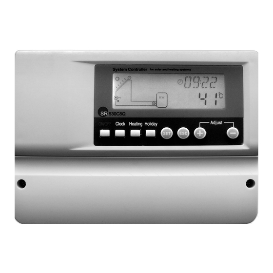
Operation manual of solar water controller SR530C8/SR530C8Q Button description “-” Parameter adjust button “+” Parameter adjust button “ESC”, exit program setup “SET” confirm button “Holiday” button(SR530C8 have no such function) “Heating”- manual heating button “Clock” button “On/off” button LCD display screen 2.Installation... -
Page 7: Preparing Before Wire Connection
Operation manual of solar water controller SR530C8/SR530C8Q ►fix cover by using screw ①②。 2.3 Power connection Power can only be switched on when the house of controller is closed, an installer must make sure that the IP protection class of the controller is not damaged during installation. -
Page 8: Terminal Connection
Operation manual of solar water controller SR530C8/SR530C8Q 2.4 Terminal connection Before to open the terminal, please be sure to switch-off the power supplier and pay attention to the local electricity supply rules. Terminal layout “ Reset” button:This button is on the terminal connection panel, when system program is out of working, press “Reset”... -
Page 9: Commissioning
100m, and then 1.5mm cable should be used. Output ports Output R1:For solar circuit pump, semiconductor relay (SCR relay), also suitable for RMP control, max. switching current 1A, Output R2:for hot water circuit pump, electromagnetic relay, and max. switching current 3.5A, R2 ports are always open, Output R3:for by-pass circuit pump or valve, electromagnetic relay, max. - Page 10 Operation manual of solar water controller SR530C8/SR530C8Q ►Press “+”“-” button to set week. ►Press “ESC” button to exit set program, or wait for 20 seconds to exit program automatically. Code Week day Monday Tuesday Wednesday Thursday Friday Saturday Sunday ---------------------------------------------------------------------------------------------------------------------------------------------------...
-
Page 11: Menu Structure
Operation manual of solar water controller SR530C8/SR530C8Q 3.2 Menu structure Menu of controller SR530C8Q Menu of controller SR530C8 Submenu: Through submenu, customer can set the parameter as desired value, please check it carefully. --------------------------------------------------------------------------------------------------------------------------------------------------- - 10 -... -
Page 12: Menu Description
Operation manual of solar water controller SR530C8/SR530C8Q 3.3 Menu description Code Code Code (Subme Menu Description Remark (Submenu) (Mainmenu) Switch-on temperature DT O difference Switch-off temperature DT F difference THET Timing heating TEMP Temperature Limited temperature of collector (Emergency turnoff temperature... -
Page 13: System Description
1 collector array – 1 storage tank – 1 pump and auxiliary heating Description: The solar circuit pump (R1) is switched on as soon as the switch-on temperature difference (△Ton) between the collector array (T1) and the storage tank (T2) is reached. -
Page 14: Controller Functions
Operation manual of solar water controller SR530C8/SR530C8Q T0: Temperature sensor for thermal energy measuring ( optional sensor) T1: Temperature sensor for collector array T2: Temperature sensor in the bottom part of tank 1. T3: Temperature sensor in the top part of tank (optional sensor) -
Page 15: Main Menu Dt O & Dt F Temperature Difference Function
4.3 Main menu DT O & DT F Temperature difference function Description: Solar circuit pump R1 is triggered by the temperature difference function, so long as the temperature difference between collector and tank reaches the switch-on DT, solar circuit pump is triggered. -
Page 16: Main Menu-Thet Timing Heating
4.4 Main menu - THET timing heating Description: Electrical heater, gas boiler or oil boiler can be integrated into solar system used as back-up of system, and they can be triggered automatically at preset time by preset temperature. Within a preset time section, when the temperature (T3) of top part of... - Page 17 Operation manual of solar water controller SR530C8/SR530C8Q on screen, the switch-on time and temperature for first time section of heating function can be set ►Repress “SET” button, “04” of hour time blinks on screen ►Press “+”“-” button to adjust hour of time ►Repress “SET”...
- Page 18 Operation manual of solar water controller SR530C8/SR530C8Q ►Press “+” button, “tH 2F 10:00” displays on screen, set the switch-off time and temperature of second time section of heating function ►Press “SET” button, “10” of hour time blinks on screen ►Press “+”“-” button to adjust hour of time ►Repress “SET”...
-
Page 19: Temp Temperature Main Menu
4.5 TEMP Temperature main menu For every system, the factory set parameters are in the best condition that is fully integrated into the entire solar system. But these parameters can also be set individually to cater the special requirements, please carefully observe the operation data of system components after setting. -
Page 20: Em Emergency Collector Temperature
Function description: When collector temperature rises up to the limited temperature (EM), this function is activated, solar circulation pump is stopped in order to avoid the damage of system other components caused by high temperature. The adjustable range of this EM temperature is (120℃~200℃), factory set is 130℃. -
Page 21: Cmn Low Temperature Protection Of Collector
And solar pump works until the temperature of collector drops since this reversed circulation or... -
Page 22: Cfr Frost Protection Of Collector
In winter when the temperature of collector is below the preset frost protection temperature (factory set is 4 C), Solar circuit pump is triggered. Besides when tank temperature (T2) drops to 4 C, electrical heater is triggered automatically and it is in operation until T2 is heated up to 20 C or it is stopped when program of CFR is exited. -
Page 23: Smx Maximum Temperature Of Tank
When the DT between collector T1 and Tank 2 caters the switch-on DT of circulation, solar pump is triggered, but in order to avoid the high temperature inside tank, controller will check whether the temperature (T3) of top part of tank is higher than maximum temperature of tank, when T3 is higher than preset SMX temperature, solar pump is ceased even at the case that DT caters condition. -
Page 24: C-F Celsius And Fahrenheit Temperature Transferring
Operation manual of solar water controller SR530C8/SR530C8Q Setup steps: To access main menu TEMP, then select submenu REC, “REC OFF” displays on screen, default set is off. ►Press “SET” button, parameter “OFF” blinks on screen ►Repress “SET” button to activate or deactivate this function, after function activated;... -
Page 25: Dvwg Anti-Legionella Function
Operation manual of solar water controller SR530C8/SR530C8Q is deactivated, then, FMAX, MEDT and MED% functions are disappeared in the submenu, only when this function (OHQM) is activated, they are just appear in the submenu. (See detailed in § 3.2 menu structure) Following submenu can be accessed through menu “FUN”... -
Page 26: Circ Temperature Controlled Hot Water Circulation Pump
4.6.2 CIRC Temperature controlled hot water circulation pump Description: Solar system can provide temperature-controlled hot water circulation function; this function needs an extra hot water circulation pump (connect output port R2) and a sensor, which is installed on the return pipe of hot water (connect input port T4). When... -
Page 27: Nmin Solar Circulation Pump Speed Adjusting (Rpm Speed Controlling)
Note: SR530C8 doesn’t have this function Description: When the switch-on temperature difference (△T ON) reaches, solar pump is triggered, and then within 20 seconds, pump speed reaches to its minimum speed (30%). Whereafter, controller checks continuously, when the standard temperature difference... -
Page 28: Ris Temperature Increase Rate (For Circuit Pump Speed Adjusting)
T1) on going and return pipe should be checked, and an extra flow meter should be installed on the circulation pipe, it is used for measuring the flow rate. The thermal energy through solar system is calculated with measured parameter temperature T1, T0 and flow rate. Thermal energy get in the current day displays in DKWh, accumulative thermal energy displays in kWh or MWh. -
Page 29: Fmax Flow Rate
Operation manual of solar water controller SR530C8/SR530C8Q Setup steps: To access main menu FUN, then select submenu OHQM, “OHQM OFF” displays on screen, Factory set is OFF ►Press “SET” button, parameter “OHQM OFF” blinks on the screen ►Repress “+”“-” button, to activate this function, “OHQM oN”... -
Page 30: Medt Type Of Heat Transfer Liquid
Operation manual of solar water controller SR530C8/SR530C8Q screen. ►Press “SET” button, parameter “2.0” blinks on the screen ►Press “+”“-” button to adjust parameter of flow rate. adjustable range(0.1~20) ► Press “ESC” button to exit the menu or wait for 20 seconds to exit automatically, parameters are saved automatically. -
Page 31: Intv Pump Interval Function
06:00 ~20:00. During the period that solar pump is in operating, (the period of running time can be set by parameter “tRUN”), controlled check the temperature signal of sensor, if the temperature increases less than 1 C, then solar pump is ceased automatically. -
Page 32: Tstp Pump Interval- Time
Description: High-temperature bypass role is independent of the solar system's operation; the extra thermal energy of tank can be transferred to other application through this function, as a result the constant tank temperature can be kept. In order to transfer this extra energy, it needs an extra pump or electromagnetic valve. -
Page 33: Hnd Manual Mode
Operation manual of solar water controller SR530C8/SR530C8Q Setup steps: To access main menu FUN, then select submenu BYPR, “BYPR------” displays on screen. ►Press “SET” button, “- - -”blinks on screen, default set is “OFF” ►Repress “SET” button, to activate by-pass function, “BYPR 80℃”... -
Page 34: Pass Password Setting
Operation manual of solar water controller SR530C8/SR530C8Q ------------------------------------------------------------------------------------------------------------------ ►Press “+” button, “HND3 off” displays on the screen, R3 output manually set ►Press “SET” button, “HND3 on” displays on the screen, R3 output is switched-on ►Repress “SET” again, “HND3 off” displays, R3 output is switched-off ►Press “ESC”... -
Page 35: Load Recovery To Factory Setting
Operation manual of solar water controller SR530C8/SR530C8Q ►Repress “SET” button, the third digital blinks ►Press “+”“-” button to enter the third digital ►Repress “SET” button, the fourth digital blinks ►Press “+”“-” button to enter the fourth digital ►Press “SET” button, “PWDN 0000” displays... -
Page 36: On/Off Button
Note: SR530C8 doesn’t have this function Description: This function activates in night, solar liquid will flow from storage tank to collector to cool the tank, and therefore to prevent high thermal loads problem of the solar system due to completely heated storage tank. The function is activated at night between 10... -
Page 37: Manual Heating
Operation manual of solar water controller SR530C8/SR530C8Q 4.12 Manual heating Description: Electrical heater, gas or oil boiler can be as back-up devices in a solar system, this controller can achieve constant temperature controlling, when controller gets temperature signal of top part tank (T3) is 2 C below the preset temperature, back-up heating will be triggered. -
Page 38: Protection Function
Operation manual of solar water controller SR530C8/SR530C8Q Note: 1.Value of accumulative operation time of circuit pump (Hp), daily thermal energy (DKWH) and accumulative thermal energy (KWH) or (MWH) can only be checked after triggering of OHQM thermal energy balance function. -
Page 39: Trouble Checking
Operation manual of solar water controller SR530C8/SR530C8Q Error message Meaning Cause of error Error rectification on LCD screen Sensor wiring interrupted, Check resistance T0 sensor problem not connected or short value, replace T0 - - - circuit Thermal Connect T0or... - Page 40 Operation manual of solar water controller SR530C8/SR530C8Q most of the normal problems encountered with the controller can be found in the list below, only return the controller to seller when you are absolutely sure that none of the problems listed below is responsible for the fault.
-
Page 41: Quality Guarantee
Operation manual of solar water controller SR530C8/SR530C8Q despite the fact re-cooling function deactivate the that the is activated. corresponding switch-on functions. conditions are not satisfied. One function There is no function All inputs and No fault on can’t be selection in submenu outputs are used;... -
Page 42: Technical Data
Operation manual of solar water controller SR530C8/SR530C8Q 8. Technical data Type SR530C8Q SR530C8 Specification Appearance of 200mm×140mm×40mm 200mm×140mm×40mm controller Power supply AC230V± 10% AC230V± 10% Power consumption < 3W < 3W Accuracy of temperature ± 2 ± 2 measuring Range of collector temperature -10~220... -
Page 43: Delivery Scope
Operation manual of solar water controller SR530C8/SR530C8Q 9. Delivery scope Type SR530C8Q SR530C8 Lists Controller Operation manual PT1000 sensor (size:φ6*50mm,cable length1.5m) NTC10K(size:φ6*50mm,cable length1.5m) Plastic expansion screw Screw Strain-relief clamp 10. Device matchable to this controller Sensor for collector: high accuracy PT1000 sensor(A01) ...
Need help?
Do you have a question about the SR530C8Q and is the answer not in the manual?
Questions and answers