Table of Contents
Advertisement
Advertisement
Table of Contents

Subscribe to Our Youtube Channel
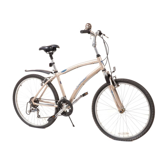
Summary of Contents for Venture Cycle LandRider
-
Page 1: Assembly Instructions
ASSEMBLY INSTRUCTIONS Version 4... - Page 2 We recommend that you have a friend help you assemble the LandRider. Relax and be patient. Your safety is important. CUSTOMER SERVICE If you have any questions please call LandRider at: 1-800-945-5335 or email us at service@landrider.com WARNING: These Assembly Instructions are a supplement to your Owner’ s Manual.
- Page 3 C) Remove the protective caps from the Wheel Hubs on the Front and Rear Wheels. STEP 2: PRE-ASSEMBLY CHECK Lay out all the components and tools for a pre-assembly check list. If any parts are missing, call LandRider at: 1-800-945-5335. Pre-Assembly Check List Main Box 1.
- Page 4 STEP 3: MANUAL Open the Owner’ s Manual to page 3 which shows a photo of the LandRider identifying all the components. This will help you while assembling the LandRider. STEP 4: STAND FRAME UP Carefully stand the bike up using the Fork ends as a stand. Make sure the Fork is facing forward as per the drawing below.
- Page 5 STEP 5: CONNECTING HANDLEBAR A) Remove the protective cardboard and rubber cap from the bottom of the Handlebar Stem Cone. (See FIG. 2). B) Remove plastic plug on top of Stem Bolt. Before inserting the Stem into the Head Tube you may need to loosen the Stem Bolt slightly 1-3 turns counter clockwise so the Stem Cone will fit into theHead Tube (See FIG.
- Page 6 STEP 6: CONNECTING SEAT POST The action of the Quick Release Cam squeezes the Seat Collar around the Seat Post to hold the Seat Post securely in place. The amount of clamping force is controlled by the Tension Adjusting Nut. Turning the Tension Adjusting Nut clockwise while keeping the Quick Release Lever from rotating increases clamping force;...
- Page 7 STEP 7: ADJUSTING FRONT REFLECTOR Adjust Front Reflector which has been turned in for shipping. Use Philips screwdriver to loosen Reflector Adjustment Bolt and then adjust to forward vertical position and retighten. (See FIG. 9). FIG. 9 Front Reflector Reflector Adjustment Bolt STEP 8: OPENING FRONT BRAKE You will need to release the Front Brake Arm so you can complete Step 10 and put the Front Wheel on.
- Page 8 STEP 9: TURN BIKE OVER For steps 10, 11 & 12 we recommend you turn the bike over, balancing it on the Handlebars and the Seat. (See FIG. 12). STEP 10: INSERTING FRONT WHEEL A) If you haven’t already remove the plastic protective spacer from the bottom of the Fork. B) Ensure protective caps on sides of Front Wheel are removed.
- Page 9 STEP 11: FRONT WHEEL QUICK RELEASE In this step you will secure the Front Wheel using the Front Wheel Quick Release. IMPORTANT: Before doing this, read the following as a thorough understanding of the Front Wheel Quick Release system is necessary for proper operation and safety. While it may look like a long bolt with a simple lever and nut on the ends, the Front Wheel Quick Release uses an adjustable Lever and Cam on a skewer to secure the bike’s Front Wheel to the Fork.
- Page 10 B) Holding the Quick Release Lever in the open position with your right hand tighten the Tension Adjusting Nut with your left hand until it is finger tight against the Fork Dropout. (See FIG. 14) C) Before closing the Quick Release Lever in Step D) Fig. 16 stand in front of and hold the Front Wheel with your left hand.
- Page 11 D) Move the Quick Release Lever downwards and push it into the closed position. The Lever should be parallel to the Fork Blade and curved towards the Wheel. IMPORTANT: If you can fully close the Quick Release without wrapping your fingers around the fork blade for leverage, and the Lever does not leave a clear imprint in the palm of your hand, the tension is insufficient.
- Page 12 TEP 12: RETURN BIKE TO UPRIGHT POSITION Return the LandRider to its upright position if you turned it upside down. Place the Kickstand down to allow the bike to stand on its own. (See FIG. 17). STEP 13: CONNECTING PEDALS IMPORTANT Please follow connecting Pedal instructions carefully.The Alloy Crank Arm can be damaged if...
- Page 13 STEP 14: RECONNECTING FRONT BRAKE Reconnect Front Brake by squeezing the two Brake Arms together with your right hand. Using your left hand, place the Cable Sleeve end through the Swinging Brace on the Left Brake Arm. REFER TO THE OWNER’s MANUAL IF YOU HAVE ANY PROBLEMS AND TO CHECK AND SET THE BRAKES.
- Page 14 STEP 15: ADJUSTING SEAT HEIGHT Adjust the Seat Post to the correct height for you. Your leg length determines the correct Seat and Seat Post height. To check for correct Seat height: A) Sit on the Seat B) Place one heel on a Pedal C) Rotate the Crank until the Pedal with your heel on it is in the down position and the Crank Arm vertical.
- Page 15 STEP 16: HANDLEBAR ADJUSTMENTS Now it is time to adjust the handlebar. First study FIG. 22 so you have a good understanding of the Handlebar. FIG. 22 Stem Bolt Plug Handlebar Bracket Bolts (changes tilt of Handlebar) Handlebar Bracket Stem Bolt (raises and lowers Stem in the...
- Page 16 B) Remove Stem Bolt Plug. Using largest Allen Key loosen 6mm Stem Bolt (See FIG. 23) and raise Stem up to 3.5 inches depending on your height. Do not raise Stem above Minimum Insertion Line. Check Handlebar is straight (See FIG. 24 & 25) and firmly tighten clockwise Stem Bolt Stem Bolt Plug FIG.
- Page 17 C) Loosen the 6mm Tilt Arm Bolt under the Tilt Arm. Now raise the Tilt Arm to 40° mark which is our general recommendation. Firmly tighten Tilt Arm Bolt. Handlebar Bracket Bolts FIG. 26 FIG. 27 Tilt Arm Tilt Arm Bolt D) The Handlebars should be in the correct position for riding so that the Grip is approximately 1.5 inches above the Brake Handles.
- Page 18 STEP 17: ADJUSTING FENDER A) Adjust the Fender height by loosening the Fender Bolt using the Philips Head Screwdriver. We recommend Fender follows angle of the Wheel and approximately 2” above Tire. Tighten Fender Bolt. WARNING: Make sure the Fender does not block clear view of rear Reflector. B) If necessary adjust the Fender side angle by first loosening the Bracket Bolt and then tightening, using the Philips head screwdriver.
- Page 19 Tubes). 2. The LandRider has a total of 14 Automatic gears. There are 7 for the flat (high) and 7 for the hills (low). To change between high and low you shift the Shifter on the left Handlebar Grip which changes the Front Derailleur (where the Pedals are).
- Page 20 Venture Cycle, LLC 2328 West Joppa Road, Suite 100 Lutherville, MD 21093...
Need help?
Do you have a question about the LandRider and is the answer not in the manual?
Questions and answers
I can't get my jockey wheels to align so that my chain goes back to first gear what im i doing wrong thank you