Table of Contents
Advertisement
U.S. Reg. 2,765,423
FOR YOUR SAFETY: This product must be installed and serviced by a
professional service technician, qualified in hot water boiler installation
and maintenance. Improper installation and/or operation could create
carbon monoxide gas in flue gases which could cause serious injury,
property damage, or death. Improper installation and/or operation will
void the warranty.
If the information in this manual is not
followed exactly, a fire or explosion may
result causing property damage, personal
injury or loss of life.
Do not store or use gasoline or other
flammable vapors and liquids in the vicinity
of this or any other appliance.
WHAT TO DO IF YOU SMELL GAS
• Do not try to light any appliance.
• Do not touch any electrical switch; do not
use any phone in your building.
• Immediately call your gas supplier from a
nearby phone. Follow the gas supplier's
instructions.
• If you cannot reach your gas supplier, call
the fire department.
Installation and service must be performed by
a qualified installer, service agency, or gas
supplier.
P/N 472642 Rev B - 09/11/08
WARNING
IMPORTANT SAFETY INSTRUCTIONS
READ AND FOLLOW ALL INSTRUCTIONS
SAVE THESE INSTRUCTIONS
Installation and Operation
PowerMax
AVERTISSEMENT
Assurez-vous de bien suivres les instructions
données dans cette notice pour réduire au
minimum le risque d'incendie ou d'explosion ou
pour éviter tout dommage matériel, toute
blessure ou la mort.
Ne pas entreposer ni utiliser d'essence ni
d'autres vapeurs ou liquides inflammables dans
le voisinage de cet appareil ou de tout autre
appareil.
QUE FAIRE SI VOUS SENTEZ UNE ODEUR DE GAZ:
• Ne pas tenter d'allumer d'appareils.
• Ne touchez à aucun interrupteur. Ne pas vous
servir des téléphones dansle bâtiment où vous
vous trouvez.
• Appelez immédiatement votre fournisseur de
gaz depuis un voisin. Suivez les instructions
du fournisseur.
• Si vous ne pouvez rejoindre le fournisseur de
gaz, appelez le sservice des incendies.
L'installation et l'entretien doivent être assurés par
un installateur ou un service d'entretien qualifié ou
par le fournisseur de gaz.
Instructions for
TM
Pool Heater
Model PM
®
Advertisement
Table of Contents
Troubleshooting

Summary of Contents for PowerMax PM
- Page 1 Installation and Operation Instructions for PowerMax Pool Heater Model PM U.S. Reg. 2,765,423 FOR YOUR SAFETY: This product must be installed and serviced by a professional service technician, qualified in hot water boiler installation and maintenance. Improper installation and/or operation could create carbon monoxide gas in flue gases which could cause serious injury, ®...
-
Page 2: Table Of Contents
1.5 Locating the Appliance ........4 6.3.2 High Altitude Adjustment and Set Up ....16 1.6 Locating Heater with Respect to Pool 6.4 Shutting Down the PowerMax ......16 System Loop ............. 6 6.5 Spring and Fall Operation 1.7 Locating Appliance for Correct Horizontal Vent/ Stand-by Service .......... -
Page 3: General Information
Burning Appliances and Equipment” and with the requirement of the local utility or other authorities WARNING having jurisdiction. Such applicable requirements take The PowerMax pool heater must be installed in precedence over the general instructions contained accordance with the procedures detailed in this herein. -
Page 4: Warranty
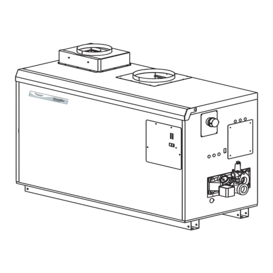
2 = Second version 1.4 Dimensions 14 Heat Exchanger (See Figure 1.) B = Glass-lined CI / copper / brz trim (std. PM) K = Bronze / copper 1.5 Locating the Appliance P = Glass-lined cast iron / cu-nickel / brz trim... - Page 5 26 30¾ 78 29½ 75 8¾ 8¾ 112 284 30 14 36 12 30 *Air and vent connections may be on top or back of the PowerMax, and are field convertible. Dimensions in inches cm . Figure 1. Dimensional Data.
-
Page 6: Locating Heater With Respect To Pool System Loop
Method 2: One permanent opening, (vertical) vent systems. commencing within 12 inches (30 cm) of the top of NOTE: When located on the same wall, the PowerMax the enclosure, shall be permitted. The opening shall combustion air intake terminal must be installed a directly communicate with the outdoors or shall minimum of 12"... -
Page 7: Intake Combustion Air
2000 3226 for personnel. The PowerMax loses less than 1 percent *Net Free Area in Square Inches / Square cm of its input rating to the room, but other heat sources Area indicated is for one of two openings; one at floor may be present. -
Page 8: Category I Vent
When the PowerMax is vented with horizontal codes. PowerMax units are not allowed to be vented discharge, it must be installed per this installation into a common horizontal vent system, unless a manual and the venting system manufacturer’s... -
Page 9: Locating Vent & Combustion Air Terminals
CAN/CGA B149.1 or .2 and local regulating, or relief equipment. applicable codes (see Figure 3). Consider the If the PowerMax uses ducted combustion air following when installing the terminal: from an intake terminal located on the same wall, Through-the-wall vent terminals must terminate locate the vent terminal at least 3 feet (0.9m) -
Page 10: Side Wall Combustion Air Terminal
A minimum 12" of vent local conditions. height is acceptable. In addition, a properly sized If the PowerMax is side-wall vented to the same single wall galvanized 90° ell can be used for the wall, locate the vent terminal at least 3 feet intake air terminal, with the open end of the ell facing (0.9m) horizontally from the combustion air... -
Page 11: Water Connections
11. Purge all air from gas lines. Caution Do not use open flame to check for leaks. NOTE: The PowerMax appliance and all other gas appliances sharing the gas supply line must be firing Figure 4. Mixing System. at maximum capacity to properly measure the inlet supply pressure. -
Page 12: Sensor Locations
The PowerMax Pool Heater is shipped with a field-installed mixing system, and must be piped in primary-secondary style, as shown. A remote pool temperature sensor and remote pool temperature high limit are wired to the PowerMax, to be mounted in the pool water loop, as shown. Figure 5. Pool Heater Piping. -
Page 13: Main Power
The setpoint will be the heat exchanger. It also controls the PowerMax displayed. Press the up arrow or down arrow buttons pump operation and the mixing system, which tempers until the desired setpoint is displayed. -
Page 14: Setpoint - Lsp
If flame is sensed, the burner will continue to fire 8). If the sensor location is farther from the heater than as long as there is a call for heat. PowerMax 1250, the capillary will reach to, then the control should be 1500, 1750 and 2000 models start at part load. -
Page 15: Filling The Heater System
To reset the standard ignition module, in operation. Problems such as failure to start, rough toggle the PowerMax power switch off, and then on ignition, strong exhaust odors, etc. can be due to again. (To reset the optional single try lockout ignition improper setup. -
Page 16: High Altitude Adjustment And Set Up
Natural Gas and LP appliances. 6.3.2 High Altitude Adjustment and Set Up PowerMax appliances may be operated at high Caution Should any odor of gas be detected, or if the gas altitude (7700 ft., 2347 m) with a reduction in output of burner does not appear to be functioning in a approximately 10%. -
Page 17: To Restart The Powermax
PowerMax Pool Heater Page 17 Improper use of the heater: This PM pool heater is not designed for continuous use as a WARNING “anti-freezing” device for pools. Operating the The U. S. Consumer Product Safety Commission heater at low water temperatures will damage the has warned that elevated temperatures in spas and heat exchanger. -
Page 18: Appliance Maintenance And Component Description
7.2.7 Ignition Controls in the reverse order. The ignition controls ensure the proved interrupted-type ignition system. They control the hot 7.2.2 Filter surface ignitor(s) and prove that the flame signal is The filter used in the PowerMax is washable with... -
Page 19: Ignitors
Use caution in handling the blower, PowerMax models 500, 750 and 1000 have one ensuring you do not put pressure on the blower wheel. ignition control. Models 1250, 1500, 1750 and 2000 have two ignition controls. -
Page 20: Trouble Shooting
5" to 13" w.c. (1.2 to 3.2 kPa) With cycle. If it is not, correct the supply problem the PowerMax running with both stages firing, set the (check gas valves or supply piping). If the supply air box pressure to 1.5" w.c. (0.37 kPa) (as a starting... -
Page 21: Troubleshooting The Pool Heater Temperature Control
4 pin connector and not at the light blue wire on that connector, replace the control. 8.6 Troubleshooting PowerMax Controls The PowerMax series consists of three models with one ignition module (500, 750 & 1000) and four models with two ignition modules (1250, 1500, 1750 and 2000). -
Page 22: Replacement Parts
The wiring schematic for the PowerMax 500 – 1000 is shown in Figure 14, and the schematic for the 1250 – 2000 models is shown in Figure 15. All 24V wiring is routed through the diagnostic PC board. - Page 23 PowerMax Pool Heater Page 23...
- Page 24 Pentair Water Commercial Pool and Aquatics Page 24...
- Page 25 PowerMax Pool Heater Page 25...
- Page 26 Pentair Water Commercial Pool and Aquatics Page 26...
- Page 27 PowerMax Pool Heater Page 27 Figure 9. Sheet Metal Components.
- Page 28 Pentair Water Commercial Pool and Aquatics Page 28 NOTE: Model 2000 shown for reference. Figure 10. Internal Components.
- Page 29 PowerMax Pool Heater Page 29 See pump chart below for pump numbers. Figure 11. Heat Exchanger Components.
- Page 30 Pentair Water Commercial Pool and Aquatics Page 30 SECTION 10. Wiring Diagrams Figure 12. PowerMax 500 - 1000 Ladder Diagram.
- Page 31 PowerMax Pool Heater Page 31 Figure 13. PowerMax 1250 - 2000 Ladder Diagram.
- Page 32 Pentair Water Commercial Pool and Aquatics Page 32 Figure 14. PowerMax 500 - 1000 Wiring Schematic.
- Page 33 PowerMax Pool Heater Page 33 Figure 15. PowerMax 1250 - 2000 Wiring Schematic.
- Page 34 Pentair Water Commercial Pool and Aquatics Page 34 Figure 16. Field Wiring, PM 500-1000.
-
Page 35: Pentair Technical Support
PowerMax Pool Heater Page 35 Technical Support Sanford, North Carolina (8 A.M. to 5 P.M.) Phone: (800) 831-7133 Fax: (919) 566-8920 Moorpark, California (8 A.M. to 5 P.M.) Phone: (800) 831-7133 Fax: (800) 284-4151 Web sites: www.pentairpool.com and www.pentaircommercial.com... - Page 36 10951 West Los Angeles Ave., Moorpark, CA 93021 • (805) 553-5000 PowerMax™ and the Pentair Commercial Pool and Spa® logo are trademarks of Pentair Water Pool and Spa, Inc. Other trademarks and trade names may be used in this document to refer to either the entities claiming the marks and names or their products. Pentair Water Pool and Spa, Inc.
Need help?
Do you have a question about the PM and is the answer not in the manual?
Questions and answers