Advertisement
FITTING AND OPERATING INSTRUCTIONS
DOMINO 1100 RC
DOMINO 1XXX, other versions
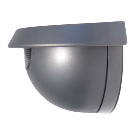
Radar motion sensors for the detection of objects for automatic gates.
SAFETY INFORMATION
The unit is only to be operated with voltages that comply with the
Safety Extra-Low Voltage (SELV) requirements in safety
standards based on IEC 60950. This unit is only to be installed
and maintained by trained, qualified personnel.
1. FITTING
1.1
OPENING THE RADAR SENSOR UNIT
from the rear, prior to installation
1.3
FASTENING AND CONNECTING-UP
Draw the cable through the opening provided
Fasten the base plate with the screws contained in the housing,
to remove and insert the electronics, observe the instructions in point 2.3
1.4
OTHER INSTALLATION OPTIONS
Optional accessory out of the 4tec accessory range.
from the front, after installation
Ceiling-mounting with mounting bracket
or
Wall fastening with weather-cap set
1.2 DRILLING
Stick the drilling template in place and drill
according to the instructions
Connect the cable to the terminals
1 power supply AC/DC
brown
2 power supply AC/DC
green
3 Main relay
white
4 Main relay
yellow
Vehicle relay
grey
Vehicle relay
pink
Advertisement
Table of Contents

Summary of Contents for Hotron Domino 1100 RC
-
Page 1: Safety Information
FITTING AND OPERATING INSTRUCTIONS DOMINO 1100 RC DOMINO 1XXX, other versions Radar motion sensors for the detection of objects for automatic gates. SAFETY INFORMATION The unit is only to be operated with voltages that comply with the Safety Extra-Low Voltage (SELV) requirements in safety standards based on IEC 60950. -
Page 2: Operating Elements
SETTING UP THE RADAR SENSOR CLOSING THE RADAR SENSOR UNIT 1. Switch on the unit and wait 10 seconds (LED flashes red/green) Insert the cover from the top and press until it clicks in place 2. Adjust the radar sensor unit / Check the setting by pacing out the distance SETTINGS OPERATING EL ENTS... - Page 3 The printed circuit board can also be inserted at a slant angle. SIZE OF THE DETECTION AREA / SENSITIVITY Turn max imum 3 steps to the right or to the left! The sensitivity potentiometer control enables the size of the detection area to be adjusted.
-
Page 4: Led Status Display
DOMINO 1100 RC Gate without separate pedestrian door. Gate control unit with 2 inputs. Vehicle detection activated, vehicle relay and main relay are connected to the Gate control unit... - Page 5 CONFIGURATION OF THE RADAR SENSOR UNIT SETTINGS WITH BUTTONS Button VALUE green/red Button MENU IR-transmitter IR-receiver Programming mode The programming mode allows to adjust the radar sensor unit with two push buttons. All settings can be read out the below programming table. The LED flashing order shows the respective settings.
- Page 6 SETTINGS WITH REMOTE CONTROL Domi-LINK The Domi-LINK allows to set the radar sensor unit easy, fast and perfectly from the floor. While the programming the sensor functions are still active. The settings can be checked immediately. Low batteries (shown on the Domi-LINK display), sunlight, fluorescent lamps and wrong orientation of Domi-LINK can reduce the range and cause transmission errors.
-
Page 7: Fault Rectification
DISTURBING INFLUENCES / INSTALLATION RECOMMENDATIONS The radar sensor unit must be installed on a firm surface. The radar sensor unit must not be No moving objects (e.g. fans, plants, trees, It must not be subject to vibration. installed behind a panel or other cover. flags, etc.) are permitted in the detection area of the radar sensor unit.


Need help?
Do you have a question about the Domino 1100 RC and is the answer not in the manual?
Questions and answers