Table of Contents
Advertisement
Advertisement
Table of Contents

Related Manuals for ekco EV55SE


Summary of Contents for ekco EV55SE
- Page 1 EKCO Manual-1.pdf 2009-11-25 9:58:33...
- Page 2 IMPORTANT SAFETY INFORMATION Caution: Changes or modifications not expressly approved by the manufacturer could void the user's authority to operate this device. This equipment has been tested and found to comply with the limits CAUTION! for a Class B digitial device, pursuant to part 15 of the FCC rules. These RISK OF ELECTRIC SHOCK limits are designed to provide reasonable protection against harmful DO NOT OPEN...
-
Page 4: Installation
INSTALLATION Place the unit on a stable rigid surface with at least 1m (3ft.) of free space above it. If you are using a turntable, ensure that the tonearm/preamplifier combination is least 400 mm away from the amplifier to minimise any hum conduction and ideally on a separate shelf. If you have to use the turntable and the amplifier on the same surface, place the turntable to the right of the amplifier to maximise the distance between the tonearm and the amplifier. -
Page 5: Connecting Signal Inputs
CONNECTIONS Signal Inputs Loudspeaker Connections Fused IEC Mains Input Ground Disc1 Disc2 Tape Tuner Right Speaker Left Speaker ON/OFF Ch. A Ch. B Ch. B Ch. A Switch Before connecting your amplifier all components in the system must be unplugged at the mains and the volume control of the amplifier set at zero. - Page 6 Standard Wiring The main loudspeakers should be connected to the “A” terminals. Connect the Left Loudspeaker to the Left channel of the amplifier. Connect the Red (Positive) terminal of the loudspeaker to the +VE terminal of the amplifier. Connect the Black (Negative) terminal of the loudspeaker to the –VE terminal of the QUAD II Classic Integrated amplifier.
-
Page 7: Operation
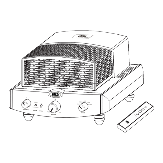
OPERATION Input Speaker Mode Volume Selector Selector Select Select Control Receiver Switching On Select an operating mode (Triode or Ultra Linear) Select the Negative Feedback level (Min or Max) Select a pair of loudspeakers (A or B) Turn the volume control fully anticlockwise to its minimum setting (0). Switch the ON/OFF switch to “I”... -
Page 8: The Remote Handset
THE REMOTE HANDSET Indicator Light Mute Button Volume UP Button Volume Down Button Installing Handset Batteries Remove the bottom cover of the handset. The batteries sit in a cradle in the handset. Carefully lift up the cradle making sure not to damage the connecting wires. -
Page 9: Further Information
FURTHER INFORMATION Running In New Equipment Running in is very important. Valve components work at high voltages and temperatures and when new they should spend an extended period at those temperatures to bed in. We recommend you run the amplifier in for at least four and preferably twelve hours before you first use it. - Page 10 Valve Types ANODE A triode valve has three elements The Anode and Cathode are connected between the Power supply and Ground. When an input is applied to the Control Grid, the amplified output appears at the CONTROL GRID anode. CATHODE Triodes are linear and robust but their amplification factor is low which makes them inefficient and limits their output power.
-
Page 11: Product Warranty
Product Warranty Your Ekco equipment is guaranteed against any defect in material and workmanship for a period of one year from the date of purchase with the exception of the valves, which are warranted for three months. Within the warranty period we will undertake replacement of defective parts free of charge provided that the failure was not caused by misuse, accident or negligence.
Need help?
Do you have a question about the EV55SE and is the answer not in the manual?
Questions and answers