Sony TC-KB920S Service Manual
Hide thumbs
Also See for TC-KB920S:
- Operating instructions manual (64 pages) ,
- Service manual (38 pages)
Table of Contents
Advertisement
SERVICE MANUAL
Dolby noise reduction and HX Pro headroom ex-
tension manufactured under license from Dolby
Laboratories Licensing Corporation. HX Pro origi-
nated by Bang & Olufsen.
"DOLBY", the double-D symbol a, and "HX PRO"
are trademarks of Dolby Laboratories Licensing Cor-
poration.
MICROFILM
TC-KB920S
Model Name Using Similar Mechanism
Tape Transport Mechanism Type
SPECIFICATIONS
STEREO CASSETTE DECK
AEP Model
E Model
Australian Model
TC-KE500S
TCM-190VB14
– Continued on next page –
Advertisement
Table of Contents

Related Manuals for Sony TC-KB920S


Summary of Contents for Sony TC-KB920S
- Page 1 TC-KB920S SERVICE MANUAL AEP Model E Model Australian Model Dolby noise reduction and HX Pro headroom ex- Model Name Using Similar Mechanism TC-KE500S tension manufactured under license from Dolby Tape Transport Mechanism Type TCM-190VB14 Laboratories Licensing Corporation. HX Pro origi- nated by Bang &...
- Page 2 LINE WITH MARK ! ON THE SCHEMATIC DIAGRAMS AND IN THE PARTS LIST ARE CRITICAL TO SAFE OPERATION. REPLACE THESE COMPONENTS WITH SONY PARTS WHOSE PART NUMBERS APPEAR AS SHOWN IN THIS MANUAL OR IN SUPPLEMENTS PUB- LISHED BY SONY.
-
Page 3: Table Of Contents
TABLE OF CONTENTS GENERAL ..............4 DISASSEMBLY ............5 MECHANICAL ADJUSTMENTS ....... 9 ELECTRICAL ADJUSTMENTS ......10 DIAGRAMS 5-1. Note for Printed Wiring Boards and Schematic Diagrams ............14 5-2. Printed Wiring Boards – MD Section – ......15 5-3. Schematic Diagram – MD Section – ......17 5-4. -
Page 4: General
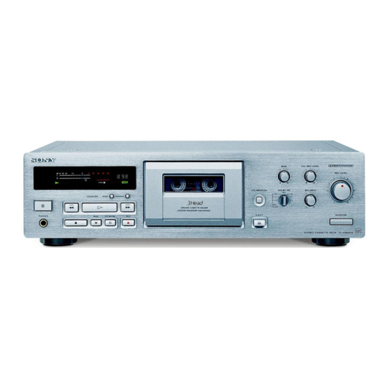
SECTION 1 GENERAL LOCATION OF CONTROLS 1 I/O (Power) button 9 § EJECT button 2 Remote control sensor !º AUTO CAL button 3 PHONES jack !¡ DOLBY NR switch 4 Display panel !™ BIAS control 5 Tape operation buttons !£ BALANCE control !¢... -
Page 5: Disassembly
SECTION 2 DISASSEMBLY Note: Follow the disassembly procedure in the numerical order given. CASE Unscrew the four case attachment seven tapping screws and remove the case. FRONT PANEL SECTION 1 three flat cables (CN803 – 805) 2 five connectors (CNP301 – 303, 305, 306) 2 connector (CN704) 4 claw... - Page 6 MAIN BOARD 4 two screws 6 MAIN board (BVTP3 × 8) 3 bracket (TR) 2 screw (BV/ring) 4 screw (BV/ring) 1 connector 5 three PC board (CN701) holders CASSETTE HOLDER (R) ASS’Y 4 cassette holder (R) ass’y 1 torsion spring 2 boss 3 shaft –...
- Page 7 FITTING BASE BLOCK 1 three screws (PTPWH2 × 23) 2 fitting base block Note: When installing, pull the FR belt and put around the claws as shown below. Note: When installing, pull the capstan belt and put around the claws as shown below. HEAD 2 erase 3 washer...
- Page 8 AUDIO BOARD AND MOTOR 2 flexible board (CNP72) 1 connector (CNP71) 6 capstan motor 3 claw 5 two screws (B2.6 × 3) 4 audio board 8 reel motor 0 ground plate 9 belt (FR) 7 two screws (P2.6 × 2.8) –...
-
Page 9: Mechanical Adjustments
SECTION 3 MECHANICAL ADJUSTMENTS PRECAUTION 2) Declination Adjustment: While in the record/playback position, set the back tension to 1. Clean the following parts with a denatured alcohol-moistened 0 (wind the supply reel with something thin like a pencil in a swab: counterclockwise direction) and make sure there is no curling record/playback/erase head... -
Page 10: Electrical Adjustments
SECTION 4 ELECTRICAL ADJUSTMENTS Note: The adjustment should be performed in the order given in the ser- Record/Playback Head Azimuth Adjustment vice manual. As a rule, adjustments about playback should be per- Procedure: formed before those about recording. 1. Mode: FWD playback The adjustments should be performed before for both L-CH and R- Test tape •... - Page 11 Tape Speed Adjustment Bias Consumption Current Adjustment Procedure: Procedure: Mode: playback LINE IN test tape (no signal) digital voltmeter CS-413 blank tape WS-48B 47 k Ω frequency counter (3 kHz, 0 dB) 47 k Ω – – TP321 3 2 1 LINE OUT B+ (+7.5 V) 1.
- Page 12 Record Level Adjustment Adjustment Location: [MAIN BOARD] – COMPONENT SIDE – Setting: REC LEVEL control: Standard Record (See page 10.) RV103 Procedure: RV203 1. Mode: record and playback LINE IN T101 T201 315 Hz, 50 mV (–23.8 dB) AF OSC CS-123 TP301 blank tape...
-
Page 13: Diagrams
SECTION 5 DIAGRAMS • Circuit Boards Location 5-1. NOTE FOR PRINTED WIRING BOARDS AND SCHEMATIC DIAGRAMS • Abbreviation (In addition to this, the necessary note is each block.) AUS : Australian : Malaysia Note on Schematic Diagram: Note on Printed Wiring Boards: : Singapore TRANSFORMER board (AEP, AUS) •... -
Page 14: Printed Wiring Boards - Md Section
TC-KB920S 5-2. PRINTED WIRING BOARDS – MD Section – • See page 13 for Circuit Boards Location. (Page 19) (Page 19) – 15 – – 16 –... -
Page 15: Schematic Diagram - Md Section
TC-KB920S 5-3. SCHEMATIC DIAGRAM – MD Section – (Page 24) (Page 24) The components identified by mark ! or dotted line with mark ! are critical for safety. Replace only with part number specified. – 17 –... - Page 16 • Waveforms – MAIN BOARD (1/2) – – MAIN BOARD (2/2) – 1 T101 4 7 IC801 #º (XIN) 4 IC304 7, 8 26.4 Vp-p 3.8 Vp-p 4.1 Vp-p 4 MHz 6.4 µ s 6.4 µ s 2 IC304 !¡, !™ 5 T301 1 4.5 Vp-p 148 Vp-p...
-
Page 17: Printed Wiring Board - Main Section
TC-KB920S 5-4. PRINTED WIRING BOARD – MAIN Section – • See page 13 for Circuit Boards Location. • Semiconductor Location Ref. No. Location Ref. No. Location D101 IC310 D102 IC311 IC701 D103 D201 IC801 D202 IC803 IC804 D203 D301 (Page 30) -
Page 18: Schematic Diagram - Main Section - (1/2)
TC-KB920S The components identified by mark ! or dotted line with mark ! are critical for safety. 5-5. SCHEMATIC DIAGRAM – MAIN Section – (1/2) • See page 18 for Waveforms. Replace only with part number specified. (Page 31) (Page 26) -
Page 19: Schematic Diagram - Main Section - (2/2)
TC-KB920S 5-6. SCHEMATIC DIAGRAM – MAIN Section – (2/2) • See page 18 for Waveforms and IC Block Diagram. (Page 31) (Page 28) (Page 28) (Page 22) (Page 17) (Page 17) (Page 31) (Page 22) The components identified by mark ! or dotted (Page 31) line with mark ! are critical for safety. -
Page 20: Printed Wiring Board - Dolby-S Section
TC-KB920S 5-7. PRINTED WIRING BOARD – DOLBY-S Section – 5-8. SCHEMATIC DIAGRAM – DOLBY-S Section – • See page 13 for Circuit Boards Location. (Page 21) (Page 21) (Page 21) (Page 21) (Page 19, 20) • IC Block Diagram IC1 CXA1917AM-T6 (DOLBY-S BOARD) -
Page 21: Printed Wiring Boards - Power Section
TC-KB920S 5-10. SCHEMATIC DIAGRAM – POWER Section – 5-9. PRINTED WIRING BOARDS – POWER Section – • See page 13 for Circuit Boards Location. (Page 27) (Page 24) (Page 19) (Page 27, 28) (Page 24) (Page 27) The components identified by mark ! or dotted line with mark ! are critical for safety. -
Page 22: Printed Wiring Boards - Panel Section
TC-KB920S 5-11. PRINTED WIRING BOARDS – PANEL Section – • See page 13 for Circuit Boards Location. (Page 19) (Page 20) (Page 20) (Page 19) (Page 19) – 29 – – 30 –... -
Page 23: Schematic Diagram - Panel Section
TC-KB920S 5-12. SCHEMATIC DIAGRAM – PANEL Section – (Page 24) (Page 23) (Page 22) (Page 21) (Page 23) – 31 – – 32 –... -
Page 24: Ic Pin Function Description
5-13. IC PIN FUNCTION DESCRIPTION • MAIN BOARD IC801 M38172M4-171FP (SYSTEM CONTROLLER) Pin No. Pin Name Function Pin No. Pin Name Function T.REEL Take-up reel rotation pulse input from the rotation detect sensor (IC82) Segment drive signal output to the fluorescent indicator tube (VFD901) SEG.DOL.C (for DOLBY NR C light up) S.REEL... -
Page 25: Exploded Views
SECTION 6 EXPLODED VIEWS NOTE: • -XX and -X mean standardized parts, so they • Items marked “*” are not stocked since they The components identified by mark ! or dotted line with mark may have some difference from the original are seldom required for routine service. - Page 26 3-020-977-01 BUTTON (AUTO CAL)(BLACK) X-3374-954-1 LID ASSY, CASSETTE (BLACK) 3-020-977-11 BUTTON (AUTO CAL)(SILVER) X-3375-905-1 LID ASSY, CASSETTE (SILVER) 3-933-299-01 KNOB (DIA. 12)(BLACK) 4-942-568-41 EMBLEM (NO.5), SONY 3-933-299-11 KNOB (DIA. 12)(SILVER) 3-020-971-11 PANEL, FRONT (BLACK)(AEP) X-3375-507-1 BASE (KB920S) ASSY, PANEL(BLACK) 3-020-971-31 PANEL, FRONT (MY,SP,AUS)
- Page 27 (3) MD ASS’Y SECTION TCM-190VB14 Ref. No. Part No. Description Remark Ref. No. Part No. Description Remark X-3368-119-1 HOLDER (R) ASSY, CASSETTE * 106 3-354-954-01 LEVER (LOCK LEVER R) 3-354-963-01 DAMPER 3-354-962-01 SPRING (EJ SAFTY SPRING R) 1-769-915-11 WIRE (FLAT TYPE)(9 CORE) 3-354-956-01 LEVER (EJ SAFTY LEVER R) 1-765-314-11 WIRE (FLAT TYPE)(7 CORE) 3-354-960-01 SPRING (LOADING R), TORSION...
- Page 28 (4) MECHANISM DECK SECTION-1 (TCM-190VB14) M902 supplied supplied supplied M901 HE301 supplied HRP301 not supplied Ref. No. Part No. Description Remark Ref. No. Part No. Description Remark 3-911-014-01 SPRING, TORSION 3-359-430-01 SPRING(CASSETTE RETAINER),LEAF 3-701-437-01 WASHER 3-359-424-01 GEAR (REV GEAR) 3-356-659-11 SPRING (RPH), COMPRESSION 3-575-321-00 RETAINER, THRUST, CAPSTAN * 154 X-3374-992-1 SLIDER (LIMITTER) ASSY...
- Page 29 (5) MECHANISM DECK SECTION-2 (TCM-190VB14) Ref. No. Part No. Description Remark Ref. No. Part No. Description Remark 3-359-469-01 SPACER 3-359-419-11 GEAR (FR GEAR) X-3368-719-2 CHASSIS(ONE)ASSY, MECHANICAL 3-359-421-01 CLUTCH (REEL DISK) 3-359-415-11 SLIDER (TRIGGER SLIDER) 3-359-418-01 PULLEY (FR PULLEY) 3-359-454-01 SPRING, TORSION 3-924-185-11 SPRING (FR ARM), TORSION 3-359-429-11 SLIDER (BRAKE PLATE) 3-936-483-01 GEAR (CAM GEAR)
-
Page 30: Electrical Parts List
AC POWER SW SECTION 7 ELECTRICAL PARTS LIST AUDIO DOLBY-S NOTE: • Due to standardization, replacements in the • Items marked “*” are not stocked since they The components identified by mark ! or dotted line with mark are seldom required for routine service. parts list may be different from the parts speci- ! are critical for safety. - Page 31 DOLBY-S LEAF SW MAIN Ref. No. Part No. Description Remark Ref. No. Part No. Description Remark 1-216-689-11 METAL CHIP 0.5% 1/10W 1-216-615-11 METAL CHIP 0.5% 1/10W < CAPACITOR > 1-208-462-41 RES,CHIP 1/10W 1-208-812-11 RES,CHIP 1/10W C101 1-126-963-11 ELECT 4.7uF 1-216-615-11 METAL CHIP 0.5% 1/10W C102...
- Page 32 MAIN Ref. No. Part No. Description Remark Ref. No. Part No. Description Remark C226 1-130-468-00 MYLAR 560PF C831 1-104-665-11 ELECT 100uF C227 1-136-433-11 FILM 100PF 630V C228 1-130-474-00 MYLAR 0.0018uF 5% < CONNECTOR > C230 1-106-351-00 MYLAR 2200PF 200V C231 1-126-964-11 ELECT 10uF CN101...
- Page 33 MAIN Ref. No. Part No. Description Remark Ref. No. Part No. Description Remark D814 8-719-911-19 DIODE 1SS119 Q316 8-729-900-74 TRANSISTOR DTC143TS Q351 8-729-119-76 TRANSISTOR 2SA1175-HFE D815 8-719-911-19 DIODE 1SS119 Q352 8-729-900-65 TRANSISTOR DTA144ES < IC > Q353 8-729-900-80 TRANSISTOR DTC114ES Q701 8-729-141-83 TRANSISTOR 2SB1094-LK IC301...
- Page 34 MAIN Ref. No. Part No. Description Remark Ref. No. Part No. Description Remark R316 1-247-872-11 CARBON 1/4W R143 1-247-843-11 CARBON 3.3K 1/4W R317 1-249-435-11 CARBON 1/4W R144 1-249-409-11 CARBON 1/4W R318 1-247-864-11 CARBON 1/4W R145 1-249-426-11 CARBON 5.6K 1/4W R152 1-247-887-00 CARBON 220K 1/4W...
- Page 35 MAIN PANEL Ref. No. Part No. Description Remark Ref. No. Part No. Description Remark R710 1-249-427-11 CARBON 6.8K 1/4W < TEST PIN > R711 1-249-425-11 CARBON 4.7K 1/4W R712 1-249-417-11 CARBON 1/4W TP301 1-564-506-11 PLUG, CONNECTOR 3P (TEST TERMINAL) ! R713 1-219-139-11 FUSIBLE 0.68 1/4W F...
- Page 36 PANEL REC VOL TRANSFORMER TRANS 1 TRANS 2 Ref. No. Part No. Description Remark Ref. No. Part No. Description Remark S902 1-572-184-11 SWITCH, KEYBOARD (AMS 0) < LINE FILTER > S903 1-572-184-11 SWITCH, KEYBOARD (AMS )) S904 1-572-184-11 SWITCH, KEYBOARD (r, REC) ! LF701 1-424-485-11 FILTER, LINE S905...
- Page 37 Ref. No. Part No. Description Remark Ref. No. Part No. Description Remark ACCESSORIES & PACKING MATERIALS ******************************** 1-776-263-11 CORD, CONNECTION (AUDIO) 1.5m 3-862-301-11 MANUAL, INSTRUCTION (ENGLISH, FRENCH, SPANISH, PORTUGUESE) 3-862-301-21 MANUAL, INSTRUCTION (GERMAN, DUTCH, SWEDISH, ITALIAN)(AEP) 3-862-301-31 MANUAL, INSTRUCTION (CHINESE)(MY,SP) –...
- Page 38 TC-KB920S Sony Corporation 98D0564-1 Printed in Japan © 1998. 4 9-922-816-11 Home A&V Products Company Published by Quality Assurance Dept. – 48 – (Shibaura)
Need help?
Do you have a question about the TC-KB920S and is the answer not in the manual?
Questions and answers