Advertisement
Quick Links
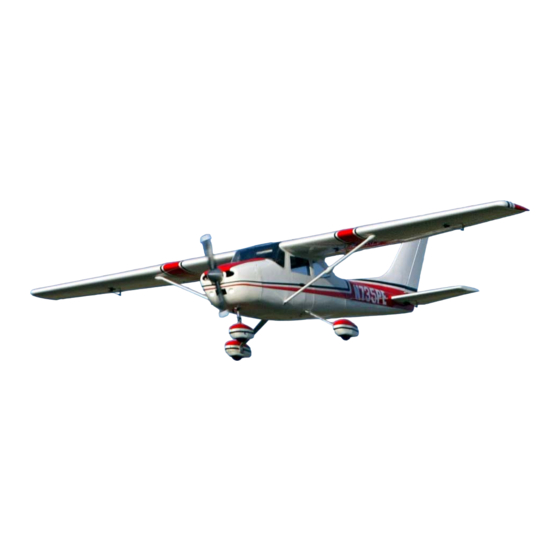
Cessna 182
ASSEMBLY INSTRUCTIONS
ASM Cessna 182 Specifications & Features
•
Wing Span: 120" (3048mm)
•
Wing Area: 2080sq.in (134.19dm²)
•
Length: 82" (2083mm)
•
Weight: 25.25 - 31lbs (11.5 - 14kg)
•
Functions: Rudder, Elevator, Ailerons, Flaps & Throttle
•
Radio: 5 Channel with 9 Servos
•
Engine: 30 to 50cc Gasoline Engine or 200 size, or larger, glow
engine
•
Advanced Lightweight Construction
•
Factory Covered Built Up Wings and Tail
•
Factory Painted Fuselage, Fiberglass Cowl and Wheel Spats
•
Strong Pre-Bent Landing Gear
•
Scale Corrugations on Control Surfaces
•
Superb, Stable Flight Characteristics
•
Full Hardware Package Included
Advertisement

Summary of Contents for ASM Cessna 182
- Page 1 Cessna 182 ASSEMBLY INSTRUCTIONS ASM Cessna 182 Specifications & Features • Wing Span: 120” (3048mm) • Wing Area: 2080sq.in (134.19dm²) • Length: 82” (2083mm) • Weight: 25.25 - 31lbs (11.5 - 14kg) • Functions: Rudder, Elevator, Ailerons, Flaps & Throttle •...
-
Page 2: Customer Service Information
Customer Service Information In the USA In the EU In Australia Global Services Ripmax Ltd. Model Engines (Aust.) PTY. LTD. 18480 Bandilier Circle 241 Green Street P.O Box 828, Noble Park, VIC., Fountain Valley, CA 92708 Enfield, EN3 7SJ, U.K. 3174 Phone: (714) 963-0329 Phone: +44(0) 20 8282 7500... - Page 3 Advanced Scale Models Cessna 182 Assembly STEP 1: Landing Gear & Wheel Spat Assembly (Main Gear) • Use some sandpaper to roughen up the inside of each wheel spat. • Use some 30 minute epoxy to glue the plywood reinforcing plates to the inside of each of the main landing gear wheel spats.
- Page 4 • Secure the axle and wheel spat assembly to the landing gear with the Nyloc style nut. • With the wheel spat level, install a self tapping screw through the pre-drilled hole in the alloy landing gear to prevent the wheel spat from rotating STEP 2: Landing Gear &...
- Page 5 STEP 4: Firewall/Engine Box Assembly • The firewall/engine box assembles from a number of laser cut plywood parts. • Dry fit the parts, but do not glue. Final gluing must be carried out with the parts in place within the fuselage. •...
- Page 6 • Using the 550 mm metal pushrod, trial fit the pushrod through the firewall with the clevis at the nose wheel end. • Note that the angle of the steering arm is angled approximately 45 degrees to the firewall to allow movement in both directions.
- Page 7 • If a gas engine is being installed, an electronic ignition module may have to be installed. This depends whether the engine is equipped with a magneto or electronic ignition system. • With electronic ignition, mount the ignition module and battery as far forward as possible. This not only assists with the centre of gravity, but also helps in isolating the receiver away from the ignition module, further reducing the possibility of interference.
- Page 8 STEP 8: Tail Plane & Rudder Assembly • Using epoxy, glue the hinges into each elevator half. • Note: To prevent the epoxy from binding the hinges, apply some light machine oil or petroleum jelly to the pivot point of each hinge. •...
- Page 9 • The rudder servo is installed in the factory fitted plywood mount in the rear fuselage section. • A 24” (600mm) servo extension lead will be required for the rudder servo. Do not secure the extension lead to the servo lead, as this will need to be disconnected when separating the two fuselage halves.
- Page 10 • Trim the two plastic covers for the rudder cable to size. • Secure in place with some medium CA adhesive. • The tail cone can now be installed using some silicon adhesive. STEP 9: Cockpit Installation (Optional), Receiver Installation & Final Fuselage Assembly •...
- Page 11 • If you are planning to enable the fuselage to be split, the two areas shown will need to be drilled out to allow access to the 4mm cap screws. • Once all the windows are fitted, access to these screws will be via the side door in the fuselage.
- Page 12 Install the wing struts using the supplied 4mm cap screws. • Slide the covers into position to cover the mounting screws. NOTE: The wing struts are functional. • DO NOT fly the ASM Cessna 182 without the wing struts fitted.
- Page 13 The ailerons are quite responsive and some rudder can be mixed in with aileron for scale co-ordinated turns. • Flaps are very effective and the ASM Cessna 182 will happily land quite slowly with only one stage of flap into a slight breeze. •...
- Page 14 Our Guarantee Advanced Scale Models guarantees this kit to be free from defects in both material and workmanship at the date of purchase. This does not cover any component parts damaged by use, misuse or modification. In no case shall Advanced Scale Models’ liability exceed the original cost of the purchased kit.
Need help?
Do you have a question about the Cessna 182 and is the answer not in the manual?
Questions and answers