Table of Contents
Advertisement
Available languages
Available languages
MicVALVE
OVL
1
VALVE
-1
-3
2
-6
-9
3
INS
-12
4
PRE
-18
5
POWER
-24
6
48 V
-30
7
-40
8
Ø
-60
Input
Fine
Bass
Angel
Valve Drive
dBu FS
Gain
Warmth
Zoom
Gain
L i n e
Mic
5
5
5
OFF
6
9
4
6
4
6
4
6
+24
+20
3
7
3
7
3
7
3
2
8
2
8
2
8
2
+14
+10
3
12
1
9
1
9
1
9
1
-40
0
0
10
0
10
0
10
0
0
15
dB
cold
warm
min.
max.
dB
hard
-30
-10
LEFT
-20
D19 MicVALVE
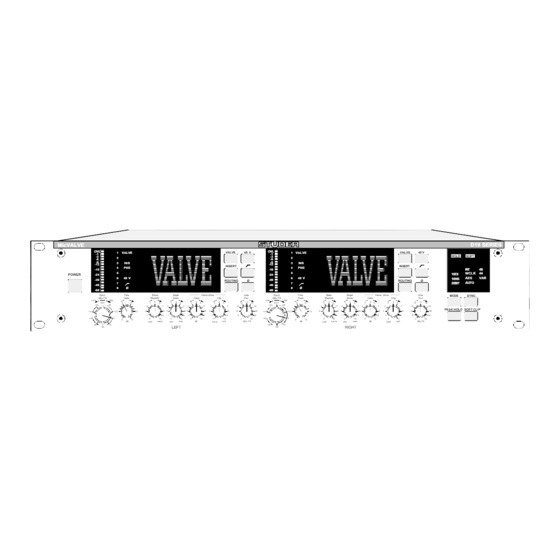
Valve-Dignified Mic/Line Preamplifier
Operating Instructions
D19 SERIES
VALVE
48 V
OVL
1
VALVE
VALVE
48 V
-1
-3
HOLD
SOFT
2
-6
-9
3
INS
-12
INSERT
INSERT
4
PRE
-18
INT
48
5
16DI
WCLK
44
-24
6
48 V
AES
VAR
-30
16NS
ROUTING
Ø
ROUTING
Ø
AUTO
7
20BIT
-40
8
Ø
-60
Line
Input
Fine
Bass
Angel
Valve Drive
Line
MODE
SYNC
Clip
Out
dBu FS
Gain
Warmth
Zoom
Gain
Clip
Out
Line
Mic
5
1 4
5
5
5
5
14
4
6
12
16
O F F
6
9
4
6
4
6
4
6
4
6
12
16
+24
+20
7
10
18
3
7
3
7
3
7
3
7
10
18
PEAK HOLD SOFT CLIP
8
8
20
2
8
2
8
2
8
2
8
8
20
+14
+10
3
12
9
6
22
1
9
1
9
1
9
1
9
6
22
10
4
24
-40
0
0
10
0
10
0
10
0
10
4
24
0
15
soft
dBu FS
dB
cold
w a r m
min.
max.
dB
hard
soft
dBu FS
-30
-10
RIGHT
-20
Betriebsanleitung
Advertisement
Chapters
Table of Contents

Subscribe to Our Youtube Channel
Related Manuals for Studer D19 MicVALVE


Summary of Contents for Studer D19 MicVALVE
- Page 1 L i n e Line O F F PEAK HOLD SOFT CLIP cold warm min. max. hard soft dBu FS cold w a r m min. max. hard soft dBu FS LEFT RIGHT D19 MicVALVE Valve-Dignified Mic/Line Preamplifier Betriebsanleitung Operating Instructions...
- Page 2 Copyright by Studer Professional Audio AG Studer Professional Audio AG Printed in Switzerland Technical Documentation Order no. 10.27.3861 (Ed. 0497) Althardstrasse 30 CH-8105 Regensdorf – Switzerland http://www.studer.ch Subject to change Studer is a registered trade mark of Studer Professional Audio AG, Regensdorf...
- Page 3 SAFETY / SECURITE / SICHERHEIT To reduce the risk of electric shock, do not remove covers (or back). No user-serviceable parts inside. Refer servicing to quali- fied service personnel. Afin de prévenir un choc électrique, ne pas enlever les couvercles (où...
-
Page 4: First Aid
SAFETY / SECURITE / SICHERHEIT FIRST AID PREMIERS SECOURS ERSTE HILFE (in case of electric shock) (en cas d'électrocution) (bei Stromunfällen) 1. Separate the person as quickly 1. Si la personne est dans l'impos- 1. Bei einem Stromunfall die be- as possible from the electric sibilité... - Page 5 SICHERHEIT / SAFETY Installation Installation Vor der Installation des Gerätes müssen die hier aufge- Before you install the equipment, please read and adhe- führten und auch die weiter in dieser Anleitung mit re to the following recommendations and all sections of bezeichneten Hinweise gelesen und während der these instructions marked with Installation und des Betriebes beachtet werden.
- Page 6 SICHERHEIT / SAFETY Zugentlastung für den Netzanschluss Mains connector strain relief Zum Verankern von Steckverbindungen ohne mechani- For anchoring connectors without a mechanical lock sche Verriegelung (z.B. IEC-Kaltgerätedosen) empfeh- (e.g. IEC mains connectors), we recommend the fol- len wir die folgende Anordnung: lowing arrangement: Procedure: The cable clamp shipped with your unit is Vorgehen: Der mitgelieferte Kabelhalter ist selbstkle-...
-
Page 7: Ambient Temperature
Umgebungstemperatur Ambient temperature Geräte und Systeme von Studer sind allgemein für einen Um- Units and systems by Studer are generally designed for an am- gebungstemperaturbereich (d.h. Temperatur der eintretenden bient temperature range (i.e. temperature of the incoming air) of Kühlluft) von +5...+40 °C ausgelegt. Bei Installation in einem +5...+40 °C. - Page 8 UMGEBUNGSBEDINGUNGEN / AMBIENT CONDITIONS Vor der Inbetriebnahme muss das System auf allfällige interne Before putting into operation, the system must be checked for Betauung oder Eisbildung überprüft werden. Nur bei sehr internal formation of condensation or ice. Only with a minute leichter Eisbildung kann mit direkter Verdunstung (Sublimati- formation of ice, direct evaporation (sublimation) may be ex- on) gerechnet werden;...
-
Page 9: Maintenance And Repair
WARTUNG / MAINTENANCE Wartung und Reparatur Maintenance and Repair Durch Entfernen von Gehäuseteilen, Abschirmungen The removal of housing parts, shields, etc. exposes etc. werden stromführende Teile freigelegt. Deshalb energized parts. For this reason the following precauti- müssen u.a. die folgenden Grundsätze beachtet werden: ons should be observed: Eingriffe in das Gerät dürfen nur von Fachpersonal Maintenance should only be performed by trained per-... - Page 10 WARTUNG / MAINTENANCE Elektrostatische Entladung (ESD) Electrostatic Discharge (ESD) bei Wartung und Reparatur during Maintenance and Repair Observe precautions for handling devices sensitive to ATTENTION: electrostatic discharge! ATTENTION: Respecter les précautions d’usage concernant la mani- pulation de composants sensibles à l’électricité statique! ACHTUNG: Vorsichtsmassnahmen bei Handhabung elektrostatisch entladungsgefährdeter Bauelemente beachten!
- Page 11 Lötverbindungen in der Abbildung weiter unten. Bei Studer werden keine handelsüblichen SMD-Teile Studer does not keep any commercially available SMDs bewirtschaftet. Für Reparaturen sind die notwendigen in stock. For repair the corresponding devices should be Bauteile lokal zu beschaffen.
-
Page 12: Electromagnetic Compatibility
EMV / EMC Störstrahlung und Störfestigkeit Electromagnetic Compatibility Das Gerät entspricht den Schutzanforderungen auf dem The equipment conforms to the protection requirements Gebiet elektromagnetischer Phänomene, wie u.a. in den relevant to electromagnetic phenomena that are listed in Richtlinien 89/336/EWG und FCC, Part 15, aufgeführt: the guidelines 89/336/EC and FCC, part 15. -
Page 13: Ce Declaration Of Conformity
CH-8105 Regensdorf, erklärt in eigener Verantwortung, dass das Produkt declares under his sole responsibility that the product Studer D19 MicVALVE, Valve Dignified Mic/Line Pre- Studer D19 MicVALVE, Valve Dignified Mic/Line Pre- amplifier, (ab Serie-Nr. 101), amplifier, (on from serial No. 101), auf das sich diese Erklärung bezieht, entsprechend den... -
Page 14: Table Of Contents
D19 MicVALVE CONTENTS Come in!.................................E1/1 Basic Information ............................E1/1 General................................E1/2 1.2.1 Scope of Delivery............................. E1/2 1.2.2 Options ..............................E1/2 1.2.3 Accessories .............................. E1/2 Safety and Connections............................ E1/3 1.3.1 Utilization for the Purpose Intended ......................E1/3 1.3.2 Power Connection ............................ E1/3 Connector Panel .............................. -
Page 15: Come In
D19 MicVALVE COME IN! We are happy to welcome you in the steadily growing circle of the Studer D19 MicVALVE's users, and we felicitate you on your selection. Thanks to Studer's experience collected during more than 40 years of business in the professional audio products field, you may expect that the performance of your new unit will fulfill your highest demands. -
Page 16: General
D19 MicVALVE General 1.2.1 Scope of Delivery The D19 MicVALVE (order No. 66.655.000.00) is supplied with an IEC 320/C13 socket, a hex-socket-screwdriver (2.5 mm), and this manual. 1.2.2 Options Order No. Digital Audio Output Options: ADAT Interface: 8-channel optical digital audio output card 1.650.050.20... -
Page 17: Safety And Connections
Repair work may only be performed by a trained service technician. The primary fuse of the D19 MicVALVE must be replaced by a spare fuse of exactly the same type. The D19 MicVALVE must not be opened by the user –... -
Page 18: Connector Panel
D19 MicVALVE 1.3.3 Connector Panel DIGITAL MCH OUT OPTICAL OUT [11] DIGITAL MCH OUT [10] TDIF-1 INSERT SENDS INSERT RETURNS MIC INPUTS LINE INPUTS LINE OUTPUTS SYNCHRONIZATION DIGITAL OUT AES IN WCLK IN WCLK OUT AES/EBU [1] AC POWER Connector for socket IEC 320/C13. - Page 19 D19 MicVALVE [10] INSERT RETURNS Input of the insert point, on female XLR connectors, for external units. The insert points can be switched between input and output of the valve stage. Input impedance 11 kΩ, electronically balanced. [11] Optional Digital Outputs TDIF-1 eight-channel format or optical ADAT eight-channel format.
-
Page 20: Technical Specifications
D19 MicVALVE Technical Specifications (Subject to Change without Notice) A/D converter: Delta-Sigma, 64 × oversampling, resolution 20 bit, linear (modular). Analog inputs: 2 separate Mic and Line inputs on XLRs, transformer-balanced and float- ing. 2 stepped attenuators and 2 potentiometers for MIC/LINE Gain setting. -
Page 21: Synchronization
D19 MicVALVE Digital output: AES/EBU output on XLR, transformer-balanced and floating according to AES3-1992, ANSI S4.40-1992 Amplitude: 2...5 V 110 Ω Impedance: Optional digital outputs: ADAT, optical 8-channel format. TDIF-1, 8-channel, 20 or 16 bit serial audio data with sampling rate infor- mation;... -
Page 22: Primary Fuse
Primary Fuse Danger: The primary fuse is located inside the D19 MicVALVE. Repair work may only be performed by a trained service technician. The primary fuse must be replaced by a spare fuse of exactly the same type and value. The unit must not be opened by the user –... -
Page 23: Operation
D19 MicVALVE OPERATION Operating Elements [13] [12] [10] [11] D19 SERIES MicVALVE VALVE 48 V VALVE 48 V VALVE VALVE HOLD SOFT INSERT INSERT WCLK POWER 16DI 48 V 48 V 16NS ROUTING Ø ROUTING Ø AUTO 20BIT Ø Ø... - Page 24 D19 MicVALVE [4]...[6] Valve Dignifier Operative only if the function VALVE [8] is active. [4] Bass Warmth The sound of low frequencies becomes rounder; bass has more depth; vocals have more body; percussive instruments are less aggressive. The group delay behaviour due to AC coupling of the stages is different in tube amplifiers.
- Page 25 D19 MicVALVE [13] Ø Toggle key to activate the phase reverse switch of the desired channel. [14] MODE Toggle key to select the word length of the DIGITAL OUTput. 20 bit (dis- play: “20BIT”), 16 bit with dithering (display: “16DI”), or 16 bit with Noise Shaping (display: “16NS”) can be selected.
-
Page 26: Audio And Sync Connections, Pin Assignments
D19 MicVALVE Audio and Sync Connections, Pin Assignments 2.2.1 Mic and Line Inputs, Insert Returns (XLR-3f) Description Ground Input + Input – – Chassis 2.2.2 Line Outputs, Insert Sends (XLR-3m) Description Ground Output + Output – – Chassis 2.2.3 AES/EBU, Digital Output... -
Page 27: Using The Tdif-1 8-Channel Interface
2.2.6 Using the TDIF-1 8-Channel Interface The Tascam TDIF-1 digital I/O format interface is used for sending digital audio data from the D19 MicVALVE to Tascam DA-88 and compatible units. Basic characteristics: 8-channel audio data with sampling frequency information, emphasis infor- mation, and sync signal. -
Page 28: Using The Optical Adat 8-Channel Interface
D19 MicVALVE 25-pin D-Type, 25-pin D-Type, Cable configuration: Cable colors (twisted pairs) male male org/red 1 org/blk 1 gry/red 1 gry/blk 1 wht/red 1 wht/blk 1 yel/red 1 yel/blk 1 pnk/red 1 pnk/blk 1 org/red 2 org/blk 2 gry/red 2... -
Page 29: Application Ideas And Examples
D19 MicVALVE Application Ideas and Examples The D19 MicVALVE is perfectly suitable for a whole range of applications. Here are some suggestions: Portable studio with 8-channel recorder (as ADAT, DA88 or compatible unit) for valve-digni- fied direct-to-digital recordings LINE 8CH OPTICAL (ADAT), 10.325.011.00,... - Page 30 D19 MicVALVE Universal studio tool with analog and digital outputs (digital MCH output optional) Studer Mixing Console LINE LINE (analog) D19 MicVALVE AES/EBU and TDIF 8-CH (optional) or Optical 8-CH (optional) Mic/Line input unit for a digital mixing console or a digital...
-
Page 31: Wiring For External Synchronization
D19 MicVALVE 2.3.1 Wiring for External Synchronization External synchronization – D19 MicVALVE recommended practice SYNCHRONIZATION AES IN WCLK IN WCLK OUT AES IN D19 MicVALVE Sync Generator SYNCHRONIZATION AES IN WCLK IN WCLK OUT AES IN D19 MicVALVE SYNCHRONIZATION AES IN... -
Page 32: Additional Information
D19 MicVALVE ADDITIONAL INFORMATION What the Heck is Noise Shaping? It is often necessary to record on digital media accepting only 16-bit signals. In such cases, the word length of the MicVALVE's 20 bit converters is best reduced to 16 bit by selecting either the 16NS (Noise shaping) or 16DI (Dither) modes. - Page 33 The curve (4) is the same with only Dither applied. AMP1(dB ) vs FREQ(Hz) & SWI(#) D19 MicVALVE -90.00 -100.0 -110.0 -120.0 -130.0 -140.0 -150.0 More information on Noise shaping and Dithering technology is available at your nearest Studer representative. E3/2 Additional Information Date printed: 9.2.2000...
-
Page 34: Block Diagrams
D19 MicVALVE Block Diagrams 3.2.1 Global Audio Block Diagram Only one channel shown; 48 V Phantom power, Mic/Line input, Level, Phase inversion, High-pass filter, and the parameters of the switchable valve stage can be set individually per channel, while Soft Clip is a global func- tion. - Page 35 D19 MicVALVE INHALT HEREINSPAZIERT! ............................D1/1 Basisinformation .............................D1/1 Allgemeines ..............................D1/2 1.2.1 Lieferumfang ............................D1/2 1.2.2 Optionen..............................D1/2 1.2.3 Zubehör ..............................D1/2 Sicherheit und Anschlüsse..........................D1/3 1.3.1 Bestimmungsgemässe Verwendung......................D1/3 1.3.2 Netzanschluss ............................D1/3 1.3.3 Anschlussfeld............................D1/4 Technische Daten ............................D1/6 1.4.1 Audio-Daten ............................D1/6 1.4.2 Synchronisation ............................D1/7 1.4.3 Stromversorgung............................D1/7 1.4.4 Primärsicherung............................D1/8...
-
Page 36: Hereinspaziert
über nostalgische Erinnerungen hinaus – der «Röhrenklang» immer wieder erwähnt. Studer-Ingenieure haben sich daran gemacht, die Unterschiede zwischen Transistorgeräten und röhrenbestückten Verstärkern systematisch zu untersuchen. Als Resultat liegt nun der D19 MicVALVE vor, bei dem die röhren-typischen Eigenschaften in Form von einstellbaren Parametern im- plementiert wurden. -
Page 37: Allgemeines
D19 MicVALVE Allgemeines 1.2.1 Lieferumfang Der D19 MicVALVE (Bestell-Nr. 66.655.000.00) wird mit einer Kaltgerä- tekupplung (IEC 320/C13), einem Inbus-Schraubendreher (2,5 mm) und dieser Betriebsanleitung geliefert. 1.2.2 Optionen Bestell-Nr. Optionale Digital-Audio-Ausgänge: ADAT-Schnittstelle: 8-kanalige, optische Digitalaudio-Ausgangskarte 1.650.050.20 für den Anschluss von ADAT- und kompatiblen Achtspur-Bandgeräten oder anderen Geräten,... -
Page 38: Sicherheit Und Anschlüsse
Netzkabel: Die mitgelieferte Kaltgerätedose muss durch einen Elektriker mit einem passenden Netzkabel mit Netzstecker versehen werden, wenn Ihre lokale Studer-Vertretung oder Ihr Fachhändler kein passendes Netzkabel beigelegt hat. Bitte lesen Sie dazu den Abschnitt «Sicherheit» in der Einleitung dieser Betriebsanleitung. -
Page 39: Anschlussfeld
D19 MicVALVE 1.3.3 Anschlussfeld DIGITAL MCH OUT OPTICAL OUT [11] DIGITAL MCH OUT [10] TDIF-1 INSERT SENDS INSERT RETURNS MIC INPUTS LINE INPUTS LINE OUTPUTS SYNCHRONIZATION DIGITAL OUT AES IN WCLK IN WCLK OUT AES/EBU [1] AC POWER Anschluss für Kaltgeräte-Kabeldose IEC 320/C13. - Page 40 D19 MicVALVE [10] INSERT RETURNS Einschleifpunkte mit weiblichen XLR-Anschlüssen, für externe Geräte. Die Einschleifpunkte können wahlweise vor oder nach der Röhrenstufe geschal- tet werden. Eingangs-Impedanz 11 kΩ, elektronisch symmetriert. [11] Optionale Ausgänge TDIF-1-Achtkanal-Format oder optisches ADAT-Achtkanal-Format. Hereinspaziert! D1/5 Date printed: 9.2.2000...
-
Page 41: Technische Daten
D19 MicVALVE Technische Daten (Änderungen vorbehalten) A/D-Wandler: Modular, Delta-Sigma, 64-faches Oversampling (Überabtastung), Auflö- sung 20 bit, linear. Analog-Eingänge: 2 separate Mikrofon- und Line-Eingänge (XLR), transformator-symmetriert und erdfrei. Je ein Stufenschalter und Potentiometer pro Kanal zur MIC- und LINE- Verstärkungseinstellung. Kanalweise wählbare Funktionen: Hochpass (–3 dB bei 75 Hz, 12 dB/Okt., nur für Mikrofon-Eingänge), Phase, Phantomspeisung (nur für Mikrofon-... -
Page 42: Synchronisation
D19 MicVALVE Digital-Ausgang: AES/EBU-Ausgang (XLR), transformator-symmetriert und erdfrei gemäss AES3-1992, ANSI S4.40-1992 Amplitude: 2...5 V 110 Ω Impedanz: Optional digital outputs: ADAT, optisches 8-Kanal-Format. TDIF-1, 8-kanalig, 20 or 16 bit serielle Audiodaten mit Abtastfrequenz- Information; C-MOS-Pegel. Analog – Analog: Line In – Line Out:... -
Page 43: Primärsicherung
D19 MicVALVE 1.4.4 Primärsicherung Gefahr: Die Primärsicherung ist im Inneren des Gerätes angeordnet. Eingriffe im Inneren des Gerätes dürfen nur von geschulten Service-Technikern vorge- nommen werden. Die Sicherung darf nur durch eine solche des selben Typs ersetzt werden. Das Gerät darf vom Benützer nicht geöffnet werden – er- höhtes Risiko eines gefährlichen elektrischen Schlages infolge der hohen... -
Page 44: Betrieb
D19 MicVALVE BETRIEB Bedienungselemente [13] [12] [10] [11] D19 SERIES MicVALVE VALVE 48 V VALVE 48 V VALVE VALVE HOLD SOFT INSERT INSERT WCLK POWER 16DI 48 V 48 V 16NS ROUTING Ø ROUTING Ø AUTO 20BIT Ø Ø Input... - Page 45 D19 MicVALVE [4]...[6] Röhren-Klangveredler nur in Betrieb, wenn die Funktion VALVE [8] aktiv ist. [4] Bass Warmth Klang tiefer Frequenzen wirkt runder; Bässe haben mehr Tiefe, Singstim- men haben mehr Körper; perkussive Instrumente sind weniger aggressiv. Das Gruppenlaufzeitverhalten von Röhrenverstärkern ist aufgrund der AC- Kopplung zwischen den einzelnen Stufen anders als bei Transistorverstär-...
- Page 46 D19 MicVALVE [11] 48 V Ein-/Aus-Taste für die 48 V-Phantomspeisung des gewünschten Mikrofon- Eingangskanals. Kann nur bedient werden, wenn der Wähler der Eingangsempfindlichkeit auf einer der Mic-Positionen steht. Die Einstellung bleibt beim Umschal- ten auf Line-Empfindlichkeit gespeichert. [12] Ein-/Aus-Taste für das Hochpass-Filter im Mikrofon-Eingang des ge- wünschten...
-
Page 47: Audio- Und Sync-Anschlüsse, Stiftbelegungen
D19 MicVALVE Audio- und Sync-Anschlüsse, Stiftbelegungen 2.2.1 Mikrofon- und Line-Eingänge, Insert Returns (XLR-3f) Bezeichnung Masse Eingang + Eingang – – Chassis 2.2.2 Line-Ausgänge, Insert Sends (XLR-3m) Bezeichnung Masse Ausgang + Ausgang – – Chassis 2.2.3 AES/EBU, Digital-Ausgang (XLR-3m) Bezeichnung Masse Ausgang + Ausgang –... -
Page 48: Anwendung Der 8-Kanal-Tdif-1-Schnittstelle
D19 MicVALVE 2.2.6 Anwendung der 8-Kanal-TDIF-1-Schnittstelle Das Tascam-Format TDIF-1 für digitale Ein- und Ausgänge kann zum Sen- den digitaler Audiodaten vom D19 MicVALVE- zu DA-88- und kompa- tiblen Achtkanal-Geräten benützt werden. Basis-Eigenschaften: 8-Kanal-Audiodaten mit Informationen über Abtastfrequenz und Emphasis, mit Sync-Signal. -
Page 49: Anwendung Der Optischen 8-Kanal-Adat-Schnittstelle
D19 MicVALVE 25-pin, D-Typ, m Aderfarben (verdrillte Paare) 25-pin, D-Typ, m Kabel-Konfiguration: org/red 1 org/blk 1 gry/red 1 gry/blk 1 wht/red 1 wht/blk 1 yel/red 1 yel/blk 1 pnk/red 1 pnk/blk 1 org/red 2 org/blk 2 gry/red 2 gry/blk 2... -
Page 50: Anwendungsmöglichkeiten Und -Beispiele
D19 MicVALVE Anwendungsmöglichkeiten und -beispiele Der D19 MicVALVE eignet sich vorzüglich für verschiedene Anwendun- gen; hier einige Beispiele: Mobiles Studio mit 8-Kanal- Recorder (z.B. ADAT, DA88 oder kompatibles Gerät) für direkte Mikrofon-Aufzeichnun- gen, mit Klangveredelung durch die Röhrenstufe: LINE 8CH OPTICAL (ADAT), 10.325.011.00,... - Page 51 D19 MicVALVE Universelles Studio-Werkzeug mit Analog- und Digital-Aus- gang (Mehrkanal-Digital-Aus- gang als Option): Studer Mixing Console LINE LINE (analog) D19 MicVALVE AES/EBU and TDIF 8-CH (optional) or Optical 8-CH (optional) Mic/Line-Eingangseinheit für ein digitales Mischpult oder eine digitale Kreuzschiene: LINE...
-
Page 52: Verkabelung Bei Externer Synchronisation
D19 MicVALVE 2.3.1 Verkabelung bei externer Synchronisation Externe Synchronisation - D19 MicVALVE empfohlene Verkabelung: SYNCHRONIZATION AES IN WCLK IN WCLK OUT AES IN D19 MicVALVE Sync Generator SYNCHRONIZATION AES IN WCLK IN WCLK OUT AES IN D19 MicVALVE SYNCHRONIZATION AES IN... -
Page 53: Zusätzliche Informationen
Oft ist es notwendig, Digitalaudio-Daten auf einem 16 bit-Medium aufzu- zeichnen. In solchen Fällen ist vorzuziehen, die Wortbreite der 20 bit- Wandler des D19 MicVALVE auf 16 bit zu reduzieren, indem man eine der Betriebsarten 16NS (Noise Shaping) oder 16DI (Dither) wählt. Dadurch werden spezielle DSP-Algorithmen aktiviert, mit deren Hilfe die uner- wünschte Signalverschlechterung, die mit der Verkürzung der Wortbreite... - Page 54 Bearbeitung mit Dither dargestellt. AMP1(dB ) vs FREQ(Hz) & SWI(#) D19 MicVALVE -90.00 -100.0 -110.0 -120.0 -130.0 -140.0 -150.0 Weiterführende Informationen über Noise Shaping- und Dithering-Technik erhalten sie auf Wunsch bei Ihrer nächsten Studer-Vertretung. D3/2 Zusätzliche Informationen Date printed: 9.2.2000...
-
Page 55: Blockschemas
D19 MicVALVE Blockschemas 3.2.1 Globales Audio-Blockschema Gezeichnet ist nur ein Kanal. 48 V-Phantomspeisung, Mic-/Line-Ein- gangsumschaltung, Pegel, Phasenumkehr, Hochpassfilter und Parameter der zuschaltbaren Röhrenstufe können kanalweise individuell gewählt werden; Soft Clip dagegen ist eine globale Funktion, die nur für beide Kanäle ge- meinsam gesetzt werden kann.
Need help?
Do you have a question about the D19 MicVALVE and is the answer not in the manual?
Questions and answers