Table of Contents
Advertisement
ST9
ST95 5 5 5 00™
ST9
ST9
Plastic Staple
Plastic Staple
Plastic Staple
Plastic Staple
Attacher
Attacher
Attacher
Attacher
Item # 15000™
Patent(s) Pending
00™
00™
00™
Operator and
Operator and
Operator and
Operator and
Service Manual
Service Manual
Service Manual
Service Manual
Part No. 3-05-0100-01
® ® ® ®
© © © ©
Rev. 1
1
Advertisement
Table of Contents

Related Manuals for Avery Dennison ST9500

Summary of Contents for Avery Dennison ST9500
- Page 1 ST95 5 5 5 00™ 00™ 00™ 00™ ® ® ® ® Plastic Staple Plastic Staple Plastic Staple Plastic Staple Attacher Attacher Attacher Attacher Item # 15000™ Patent(s) Pending Operator and Operator and Operator and Operator and © © © © Service Manual Service Manual Service Manual...
- Page 2 IMPORTANT NOTICE: PLEASE READ CAREFULLY THE TERMS AND CONDITIONS OF THIS END-USER LICENSE AGREEMENT (“AGREEMENT”) BEFORE BREAKING THIS SEAL AND OPENING THIS PACKAGE CONTAINING THE ST9500™ PLASTIC STAPLE® ATTACHER (THE “PRODUCT”). AVERY DENNISON CORPORATION AND/OR ANY OF ITS SUBSIDIARIES (“AVERY”) IS WILLING TO LICENSE TO YOU (“YOU”...
- Page 3 This manual is copyrighted with all rights reserved and may not be copied, in part or in whole, without the written consent of Avery Dennison Corporation. Avery Dennison makes no warranty, express or implied, as to its accuracy and assumes no liability arising out of its use by others.
-
Page 4: Table Of Contents
Introduction Chapter 2 Installation Unpacking the ST9500 ……………………………………………… ......9 Mounting the ST9500 ……………………………………………….......10 Setting Up the ST9500 ………………………………………………......11 Chapter 3 Operation Operating the Front Panel………………………………………………......14 Adjusting Needle Spacing………………………………………………......18 Double Shot Mode and Single Shot Mode Switch………………..……......19 Loading Fasteners………………………………………………………......20 Adjusting the Fastener Cut ………................ - Page 5 Replacing the Crank Arm ………………………………………………… ......48 Replacing the Coupling………………………………………………..……....49 Chapter 6 Troubleshooting ST9500 Doesn’t Actuate or Actuates Abnormally…………………......51 Panel Doesn’t Display or Works Abnormally…………………........51 Host Software Application Doesn’t Function Properly………………......52 Fastener Problems …………………………………………………………......52 Ejection Problems ………………………………………………………….....53...
-
Page 6: Important Safety Instructions
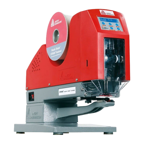
ST9500 is connected to a power source. Disconnect the power cord before attempting to replace any component. Do not operate the ST9500 with the cover removed or make any attempt to defeat the cover interlock switch. Moving parts and shock hazard can cause serious personal injury. - Page 7 Chapter 1 Introduction This manual provides all of the information required to install, operate, troubleshoot, and service the ® Avery Dennison ST9500 Plastic Staple Attacher. The ST9500 fastens garment size, pricing, and brand-name tags to fabrics by ® inserting Plastic Staple fasteners through the tag and the underlying fabric.
-
Page 8: Chapter 2 Installation
Chapter 2 Installation The chapter describes how to install the ST9500. □ Unpacking the ST9500 □ Mounting the ST9500 □ Setting up the ST9500 for operation... -
Page 9: Unpacking The St9500 Tm
Visually inspect the ST9500 and the shipping materials for damage. □ If the ST9500 is damaged, notify Avery Dennison immediately. □ If the shipping box is also damaged, notify the freight carrier as well as Avery Dennison, and save the shipping materials for the carrier to inspect. -
Page 10: Mounting The St9500 Tm
With the base rotated, the ST9500 will not stand unsupported without tipping. 2. Position the ST9500 on the work surface and mark the location of the four mounting holes in the base. 3. Drill four mounting holes in the work surface for the mounting bolts. -
Page 11: Setting Up The St9500 Tm
Make sure the power switch is in the OFF position (0), then plug the power cord into the power cord receptacle on the ST9500. Power cord receptacle on the left... - Page 12 Plug the foot switch cord into the foot switch receptacle. Connect the power cord to an electrical outlet and turn the ST9500 power switch from OFF (0) to ON (1).
-
Page 13: Chapter 3 Operation
Chapter 3 Operation The chapter explains how to operate the Avery Dennison ST9500. □ Operating the front panel □ Adjusting needle spacing □ Double shot mode and single shot mode switch □ Loading fasteners □ Adjusting the fastener cut □... -
Page 14: Operating The Front Panel
Operating the Front Panel 1. Panel General Description ST9500 panel consists of a digital display with blue backlight and white fore-colored letters and 5 membrane buttons for changing parameter settings. The 5 buttons are numbered as 1, 2, 3, 4 and 5, and their marks in the buttons are named as SPEED, INTERVAL, MODE, COUNT /RESET and SAVE. - Page 15 0.55s, 0.60s, 0.25, 0.28 …” and it will then repeat. Button “2” (“INTERVAL”): This is to change the interval. With each press the display will change to the next value of “…, 0s, 0.1s, 0.2s, 0.3s, 0.4s, 0.5s, 0.6s, 0.7s, 0.8s, 0.9s, 1.0s, 0s…”...
- Page 16 User can press the four buttons to change the parameters settings as described in above section 3. “Button Functions”. 4.4. Super Administrator Password: If you forgot the password, please contact Avery Dennison. 4.5 Password Change: You may change the password by following the display instructions.
- Page 17 5. Panel Operation Flow Chart:...
-
Page 18: Adjusting Needle Spacing
Adjusting Needle Spacing 1. Open the front door. 2. Turn the Knob and adjust the space between the two needles. When you adjust the needle spacing, please make sure that the Ejector Rods move according to the needles, if the Ejector Rods do not move then there might be some friction with the Ejector Rod guide at the top. -
Page 19: Double Shot Mode And Single Shot Mode Switch
Double Shot Mode and Single Shot Mode Switch 1. Open the front door. 2. Use a screw driver to loose the Mode Switch Knob; 3. Use the Mode Switch Knob to switch the shot mode between double shot and single shot. In double shot mode, the machine feeds two pieces of staples at a cycle, while in single shot mode the machine feeds one piece of staple at a cycle. -
Page 20: Loading Fasteners
Check that the reel rotates freely. 4. Cut the end of fasteners half way between two rungs. 5. Feed the fasteners through the upper slot on the front of the ST9500 (refer to the fastener feed diagram inside the front door, if necessary). - Page 21 6. Feed the fasteners into the plastic guide above the feed wheel. 7. Feed the fasteners down behind the feed wheel. 8. Turn the feed knob clockwise to advance the fasteners down through the knife block. 9. Continue turning the feed knob until the knife is centered between two fastener rungs.
-
Page 22: Adjusting The Fastener Cut
Adjusting the Fastener Cut If the knife is not centered between two fastener rungs, you must adjust the fasteners position. 1. Loose the nut, screw in or out to adjust the adjusting screw. Then lock the nut after adjustment. 2. Feed the fasteners and cut, and check if the fasteners are cut properly now at midway. 3. -
Page 23: Inserting A Fastener Into A Garment
The front door is equipped with an electrical interlock switch that disables power of motor when the door is opened. The door must be completely closed to operate the ST9500. Reposition the garment for the next fastener and press the foot pedal. -
Page 24: Inspecting The Fastener Cut
Inspecting the Fastener Cut 1. Inspect the fastener to see if it is inserted into the fabric correctly. Adjust the fastener cut if necessary (see page 19). -
Page 25: Theory Of Operation
Chapter 4 Theory of Operation This chapter describes the operating principles of the ST9500. You should read this chapter if you are responsible for troubleshooting and repairing the ST9500. -
Page 26: Electric Schematic Block
Panel, Footswitch and Sensors, LED lighting etc. ST9500 switching power provides the power supply for all the machine, the switching powers operates on wide range of AC voltage 110 ~ 240VAC, 50/60Hz, you do not need any transformer if the industrial power supply is within the range of 110 ~ 240VAC, 50/60Hz. -
Page 27: The St9500 Tm Cycle
The ST9500 Cycle ® The ST9500 inserts one or two Plastic Staple fastener(s) each cycle. Typically, the fastener attaches a ticket to a piece of fabric. How many cycles per press of the footswitch would the motor run? It depends on the settings of the cycle mode. - Page 28 □ After the Head goes all the way down to the bottom, it turns to go up; when the head comes up , the feed pawl engages the ratchet on the feed wheel, advancing one or two (depends on setting) new fastener(s) into the cut position.
-
Page 29: Parts Replacement
Do not operate the machine without the enclosure and needle guard. Needles and moving parts cause serious personal injury. 2. Make sure the Power Switch is OFF (0) and plug in the power cord. The ST9500 should not cycle. 3. Turn the Power Switch ON (1). Check that motor is running. -
Page 30: Removing The Enclosure
Do not attempt to remove the enclosure, or service or disassemble ! ! ! ! W ARNING any component while the ST9500 is connected to a power source. Disconnect the power cord before attempting to replace any components. Do not operate the ST9500 with the enclosure removed or make !... -
Page 31: Replacing The Door Needle Guard
Replacing the Door Needle Guard Door Needle Guard Disassembly 1. Open the front door. 2. Remove the four screws holding the door needle guard. 3. Remove the door needle guard. ! ! ! ! W ARNING Do not operate the machine with the needle guards removed. Needles and moving parts may cause serious personal injury. -
Page 32: Replacing The Needle Guard
Replacing the Needle Guard Needle Guard Disassembly 1. Open the front door. 2. Remove the four screws holding the needle guard. 3. Remove the needle guard. ! ! ! ! W ARNING Do not operate the machine with the needle guards removed. Needles and moving parts may cause serious personal injury. -
Page 33: Replacing The Needles
Replacing the Needles Needle Lock Screws Scallop Cut Needles Disassembly ! ! ! ! W ARNING Needles are extremely sharp and can puncture skin with a minimal amount of pressure. Use extreme care when handling. 1. Unplug the unit. 2. Open the front door. 3. -
Page 34: Replacing The Ejector Rods
Replacing the Ejector Rods Scale Plate Slide Ejector Rod Ejector Rod Entrance Fastener Ejector Block Disassembly 1. Unplug the unit. 2. Open the front door. 3. Loosen the screw holding the scale plate for access to the black ejector slide, move the scale plate up and tighten the screw. -
Page 35: Replacing The Knife
Replacing the Knife Knife lever Left needle block Hold Knife Spring Spring cover Right needle block Knife Knife block Disassembly 1. Unplug the unit. 2. Open the front door. 3. Remove the needle guard (see page 29). 4. Remove the tighten screws on the right and left needle blocks, then push the knife lever so as to remove the right and left needle blocks. -
Page 36: Replacing The Feed Wheel
Replacing the Feed Wheel Feed Wheel Assy. Disassembly Unplug the unit. Disconnect the pawl spring. 3. Remove the two screws holding the left support plate and then remove the plate. 4. Remove the two screws holding the right support plate and then remove the plate. 5. - Page 37 Assembly Slide the right support plate over the feed wheel shaft. (Countersunk holes on the plate face out.) Replace the feed knob spring and tighten the setscrew. Reattach the right support plate to the head. Reattach the left support plate. Reattach the pawl spring.
-
Page 38: Removing The Head Assembly
Removing the Head Assembly Head Assembly Sensor Assembly Feed Stop Slide Plate Ejector Slide Disassembly Unplug the unit. Remove the reel support and the enclosure. Remove the screw on the Feed Stop, and remove the Feed Stop. Remove the screw on the Sensor assembly and remove the Sensor assembly. Remove the two screws on each Slide Plate and then remove the Slide Plates. - Page 39 Assembly Place the crank bushing in the middle of the horizontal track on the back of the head. Rotate the crank arm so the drive pin is at top dead center. Crank Arm These two surfaces should align well Slot in Knife Block Orient the ejector slide to make the top of the slide flush with the top of the slide’s guide track.
-
Page 40: Removing The Ejector Slide
Removing the Ejector Slide Staple Guide Ejector Slide Slide Plate Guide Bar Feed Wheel Assy. 1. Unplug the unit. 2. With head and EJ slide in top position. 3. Remove the feed wheel assembly (see page 33). 4. Remove the four screws holding the feed guide and then remove the feed guide. 5. -
Page 41: Replacing The Knife Lever
Replacing the Knife Lever Disassembly Unplug the unit. Remove the feed wheel assembly (see page 33). Remove the feed guide and the ejector slide (see page 37). Disengage the spring from the bottom of the knife lever. Remove the snap ring from the left side of the knife lever shaft. Slide the shaft out and remove the lever and spring. -
Page 42: Replacing And Aligning The Gears
Replacing and Aligning the Gears NOTE The gears only need to be aligned if you replace them or if you removed the head when the ejector slide was removed and you didn’t keep the gears aligned by inserting a tool into the alignment hole in the left side of the head (see page 37). - Page 43 Assembly Hold the gears in the gear slots cut in the head, with the large gear on the right. Insert the gear shaft through the right side of the head and the gears. Replace the snap ring on the left side of the gear shaft. Rotate the gears so that the white timing mark on the large gear is in the front.
-
Page 44: Replacing The Circuit Board
Replacing the Circuit Board Circuit board Rear Door Disassembly Unplug the unit. Remove the reel support and the enclosure. Loosen but don’t remove the thumb screw on the Rear Door, rotate the Rear Door by 180 degrees and hang it on the thumb screw. Disconnect the connectors. -
Page 45: Replacing The Capacitor
Replacing the Capacitor Circuit board assembly Capacitor Rear Door Disassembly Unplug the unit. Remove the reel support and the enclosure. Loosen but don’t remove the thumbscrew on the Rear Door, rotate the Rear Door by 180 degrees and hang it on the thumbscrew. Remove the circuit board (see page 46). -
Page 46: Replacing The Motor, Coupling, And Crank Arm Assembly
Replacing the Motor, Coupling, and Crank Arm Assembly Motor Coupling Crank Disassembly Unplug the unit. Remove the reel support and the enclosure. Unplug the motor, interlock switch, solenoid, and light connectors from the circuit board. Sensor Assy. Interlock Switch Mount Base LED Light 4. - Page 47 Assembly Make sure the head is in the top position. Make sure the crank bushing is in the center of the horizontal track on the back of the head. Make sure the crank arm pin is at top dead center. Head Assy.
-
Page 48: Replacing The Crank Arm
Replacing the Crank Arm Coupling Crank Arm Motor Holder Disassembly Unplug the unit. Remove the motor, clutch, and crank arm assembly (see page 45). Remove the screws holding the crank arm. Remove the crank arm. Assembly Place the Key in the slot of crank arm. Place the crank arm on the face of the coupling, aligning the pin on the crank arm with the cog on the coupling. -
Page 49: Replacing The Coupling
Removing the Coupling Coupling Crank Arm Motor Disassembly 1. Unplug the unit. 2. Remove the motor, coupling, and crank arm assembly (see page 48). 3. Remove the crank arm (see page 50). 4. Remove the screw in the coupling holding the motor shaft. 5. -
Page 50: Chapter 6 Troubleshooting
Needles and moving parts may cause serious personal injury. Make sure the Power Switch is OFF (0) and plug in the power cord. The ST9500 should not cycle. Turn the Power Switch ON (1). Check that motor is not running, the panel LCD displays well, and the LED light is on. -
Page 51: St9500 Doesn't Actuate Or Actuates Abnormally
ST9500 Doesn’t Actuate or Actuates Abnormally Symptom Probable Cause Action Check that the power cord is properly connected No power supply and the switch is powered on The front door is not closed Close the front door properly so that the... -
Page 52: Host Software Application Doesn't Function Properly
Host Software Application Doesn’t Function Properly Symptom Probable Cause Action RS232 connector loose Check the connection Serial Port (RS232) Select a correct COM cannot get connected Wrong COM port selected port Network connector loose Check the connection Network cannot get Check and make sure the IP connected IP address not setup or wrongly setup... -
Page 53: Ejection Problems
Ejection Problems Symptom Probable cause Action Fastener not ejecting Bent ejector rods Replace rods. Ejector rods bending Ejector slide not installed Readjust slide. correctly Knife too tight Check that knife can move freely. Broken knife lever spring Replace spring. -
Page 54: Routine Maintenance And Lubrication
This is the only daily maintenance required. CAUTION Do not use any type of lubricant on the fastener path. Use only compressed air to clean it. Do not use any solvents on the ST9500. ! ! ! ! W ARNING... -
Page 55: Lubrication
Lubrication You should lubricate the ST9500 approximately every six months or one million cycles. The following areas should be lubricated with light grease: Sliding surfaces Sliding surfaces on Head on Mount 1 way bearing Gear sets Sliding surfaces on Ejector Slider... - Page 56 Routine Maintenance and Lubrication The following areas should be lubricated with light sewing machine oil:...
-
Page 57: Chapter 8 Parts List
You will need the following information: The Avery Dennison part number and description from the list in this chapter The model number and serial number located on the back of the ST9500™ machine. Factory Service Depot factory service may be available. Contact your local Fastener Division sales office. - Page 58 Whole Machine Exploded Illustration...
- Page 59 Whole Machine Spare Parts List Item P/N Description Qty. 3-06-0002-01 Assy, Base 3-06-0003-01 Assy, Body 3-06-0006-01 Assy, Motor 3-06-0013-01 Assy, Head 3-05-0048-01 Clamp, Mount Right 3-05-0049-01 Clamp, Mount, Left 3-06-0022-01 Assy, Hall sensor 140012012101 Washer, Black D4 140012008001 Lock Washer, Black D4 10 140001057401 Screw, Hexagon Socket Cup Head, Black 4X12 140001001201...
- Page 60 Base Assembly and Body Assembly Exploded Illustration...
- Page 61 Base Assembly and Body Assembly Spare Parts List: Item P/N Description Qty. 3-05-0001-01 Base 3-05-0002-01 Arm, Reactor 3-05-0003-01 Plate, Reactor DT0005-001 Pin 5, Locating ST0605-001 Machine Buffer 140001022901 Screw, Hexagon Socket Cup Head, Black 6X25 140012008601 Washer, Black D6 140012008101 Lock Washer, Black D6 140001057701 Screw, Hexagon Socket Cup Head, Black 4X8...
- Page 62 Motor Assembly Exploded Illustration...
- Page 63 Motor Assy Spare Parts List: Item Description Qty. 3-06-0007-01 Assy, Mount 3-05-0007-01 Mount 3-05-0008-01 Wear Strip DT0210-001 Rack-6 3-05-0009-01 Holder, Motor 110013016301 Bearing, Needle Roller 140001002501 Screw, Hexagon Socket Cup Head, Black 5X20 140012015801 Washer, Black D5 140012010601 Lock Washer, Black D5 140003006201 Screw, Hexagon Socket Countersunk Head, Black 4X10 140001000302...
- Page 64 116 140001057601 Screw, Hexagon Socket Cup Head, Black 4X6 117 140012008001 Lock Washer, Black D4 118 140002006502 Screw, Half-Round Crossed Head, Stainless Steel 3X14 119 140012007901 Lock Washer, Black D3 120 3-06-0011-01 Assy, Lamp 121 3-05-0011-01 Plate, Lamp 122 ST0324-001 Shade, Lamp 123 140001057101 Screw, Hexagon Socket Cup Head, Stainless Steel 2X5...
- Page 65 Head Subassembly and Knife Lever Assembly Exploded Illustration...
- Page 66 Head Subassembly and Knife Lever Assembly Spare Parts List: Item P/N Description Qty. 3-06-0014-01 Sub Assy, Head 3-05-0013-01 Housing 3-05-0014-01 Block, Slide, Rear, Shot Mode 3-05-0015-01 Block, Slide, Front, Shot Mode 110020003101 Ball detent 3-05-0016-01 Adjust Rod, Space, Shot Mode 110015022401 Pin, Spring DT0108-001...
- Page 67 Base, Knife Assembly Exploded Illustration...
- Page 68 Base, Knife Assembly Spare Parts List: Item P/N Description Qty. 180 3-06-0016-01 Assy, Base, Knife 181 3-05-0018-01 Base, Knife 182 3-05-0019-01 Support, Shaft 183 3-05-0020-01 Nut, Right 184 3-05-0021-01 Bolt, Adjust 185 3-05-0022-01 Nut, Left 186 3-05-0023-01 Handle, Adjust 187 3-05-0024-01 Block, Guide, V Shape 188 3-05-0025-01 Block, Guide...
- Page 69 Left and Right Needle Holder Assembly Exploded Illustration...
- Page 70 Left and Right Needle Holder Assembly Spare Part List: Item Description Qty. 210 3-06-0017-01 Assy, Holder, Needle, Left 211 3-05-0029-01 Holder, Needle, Left 212 3-05-0030-01 Block, Guider, Left 213 3-05-0083-01 Screw, Needle Lock 214 3-05-0078-01 Plate, Rod Block, Left 216 15010-0 Plastic Staple®...
- Page 71 Guide Bar Assy., Feed Assy. and Feed Lever Assy. Exploded Illustration...
- Page 72 Guide Bar Assy., Feed Assy. and Feed Lever Assy. Spare Parts List: Item Description Qty. 3-06-0019-01 Assy, Guide Bar 3-05-0035-01 Guide Bar, Staple 3-05-0036-01 Plate, Guide DT0133-001 Guide, L-shaped Staple 140001001201 Screw, Hexagon Socket Cup Head, Black 4X10 140012008001 Lock Washer, Black D4 140012012101 Washer, Black D4 140001000802...
- Page 73 Hall Sensor Assy., Feed Stop Assy. and other Parts Exploded Illustration Hall Sensor Assy., Feed Stop Assy. and other Parts Spare Part List Item Description Qty. 3-05-0033-01 Ejector Slide 3-05-0045-01 Slide, Ejector 7-60-2733-01 Rod, Ejector 3-05-0046-01 Plate, Scale 3-05-0081-01 Plate, Screw 3-05-0034-01 Entrance, Staple 140001001201...
- Page 74 Switch Power Supply Assy. and Driver Assy. Exploded Illustration...
- Page 75 Switch Power Supply Assy. and Driver Assy. Spare Part List Item P/N Description Qty. 321 3-05-0051-01 Bracket, Power 322 130036006201 Power Supply, Switching 323 140001000802 Screw, Hexagon Socket Cup Head, Black 3X6 324 140012007901 Lock Washer, Black D3 325 140012012201 Washer, Black D3 326 140001057601 Screw, Hexagon Socket Cup Head, Black 4X6...
- Page 76 Cover R & L Assy. Exploded Illustration: Cover R & L Assy. Spare Part List: Item Description Qty. 3-06-0027-01 Assy, Cover R & L 3-05-0055-01 Cover, Left 3-05-0056-01 Cover, Top 3-05-0057-01 Cover, Right 3-05-0058-01 Board, Wire DT0018-001 Spring, Front Door 3-05-0088-01 Cover, Screw 3-05-0085-01...
- Page 77 Door Enclosure Assy. Exploded Illustration:...
- Page 78 Door Enclosure Assy. Spare Part List: Item Description Qty. 3-06-0028-01 Assy, Door Enclosure 3-06-0029-01 Assy, Cover, Front 3-05-0059-01 Cover, Front 3-05-0060-01 Door, Needle Guard 3-05-0084-01 Piece, Front Door 140001000802 Screw, Hexagon Socket Cup Head, Black 3X6 DT0028-001 Washer, 3X12 3-06-0030-01 Assy, Panel 3-05-0061-01 Board, Support...
-
Page 79: Chapter 9 Contact Information
Apodaca, Nuevo Leon 66600 Mexico Phone: 52 (81) 8864-4100 Fax: 52 (81) 8864-4101 Email: fastener.mexico@averydennison.com BRAZIL Avery Dennison do Brasil Ltda. Rua Francisco Foga, 225 CP 18 – CEP 13280-000 Vinhedo-SP, Brasil Tel: 55-19-3876-7696 / 0800-7010076 Fax: 55-19-3876-6763 Email: fastener.brazil@averydennison.com Visit us on the web at www.fastener.averydennison.com... - Page 80 KOREA ASIA Avery Dennison Korea Ltd. 872, Kwan Yang 2-Dong, DongAn-Ku HONG KONG AnYang-Si, Kyounggi-Do Avery Dennison (HK) Ltd. Korea 431-062 1/F., No. 7 Chun Ying Street Phone: 82-31-425-6140 Tseung Kwan O Industrial Estate Fax: 82-31-425-6145 Email: info_fap@ap.averydennison.com ERRITORIES Hong Kong...
Need help?
Do you have a question about the ST9500 and is the answer not in the manual?
Questions and answers