
Related Manuals for intrepid 350 WALKAROUND

Summary of Contents for intrepid 350 WALKAROUND
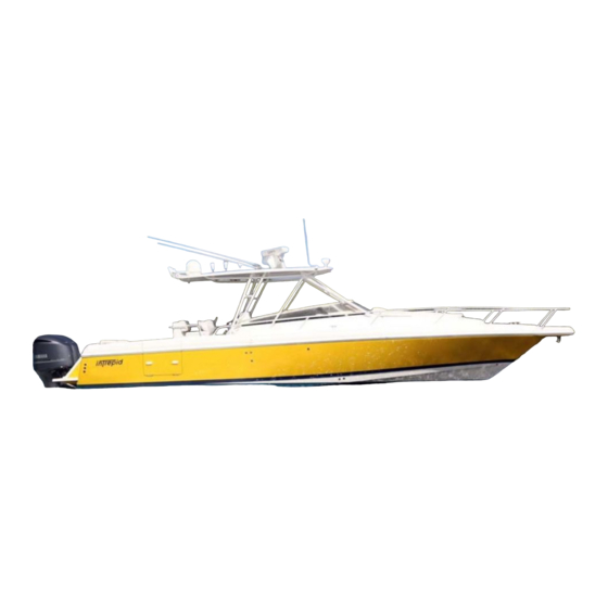
- Page 1 OWNER’S MANUAL WALKAROUND INTREPID POWERBOATS, INC. 11700 SOUTH BELCHER ROAD 11700 SOUTH BELCHER ROAD LARGO, FL 33773 PHONE (727)548-1260 (727)544-1796...
-
Page 2: Table Of Contents
TABLE OF CONTENTS BOAT DATA OWNER’S DATA BOAT DATA A WORD OF WELCOME WARRANTY INFORMATION WARRANTY CUSTOMER’S RESPONSIBILITY CONTROL HELM SPEED AND MANEUVERING CONTROLS ENGINE THROTTLE AND SHIFTER IGNITION SWITCHES STEERING BOAT AND ENGINE TRIM TRIM TAB SYSTEM ENGINE TILT AND TRIM ENGINE INSTRUMENTATION THE IMPORTANCE OF ENGINE INSTRUMENTATION BASIC ENGINE INSTRUMENTATION... - Page 3 ACCESSORIES (continued) BILGE PUMP #1 D-13 BILGE PUMP #2 D-14 CABIN BILGE PUMP D-14 COCKPIT LIGHTS D-16 ACCESSORY # 1 D-16 ACCESSORY # 2 D-17 OVERHEAD LIGHT OPTION D-17 ACCESSORY # 3 D-17 SPREADER LIGHT OPTION D-18 ACCESSORY # 4 D-18 ACCESSORY # 5 D-19...
- Page 4 GENERATOR CONTROLS ACCESSORIES HALON FIRE EXTINGUISHER CO MONITOR BOW THRUSTER SYSTEM DC DISTRIBUTION THRUSTER CONTROL THRUSTER OPERATION OPERATING YOUR INTREPID OPERATING YOUR INTREPID STARTING THE ENGINES RUNNING YOUR INTREPID PERFORMANCE ENGINE EFFICIENCY ATMOSPHERIC CONDITIONS PERSONAL EQUIPMENT AND ACCESSORIES MARINE GROWTH...
- Page 5 PROPELLERS MAINTAINING YOUR INTREPID MAINTAINING YOUR INTREPID DAILY / WEEKLY MAINTENANCE 100 HOURS OR 60 DAYS EXTERIOR INTERIOR BILGE AREAS CONTROL HELM FIBERGLASS AND GELCOAT CARE LEAVING YOUR INTREPID LEAVING YOUR INTREPID SHORT TERM LONG TERM STORING DRY STORAGE WET STORAGE...
-
Page 6: A Word Of Welcome
The step-lift hull is a state-of-the-art design that reduces the wetted surface of the hull bottom, which means less drag and higher performance. Your Intrepid is built of the finest, most modern materials and is manufactured under rigid quality controls. The hull is constructed of high-impact hand laid up multi-laminate fiberglass. Your boat comes to you as the most thoroughly tested and trouble free boat on the market today. -
Page 7: Warranty
CONDITIONS OF WARRANTY. As a condition of Intrepid Powerboat, Inc.’s obligations under this Warranty the first purchaser at retail shall: 1. Within ten (10) days of the date of sale, complete and mail to Intrepid Powerboats, Inc. the Owner’s Warranty Registration attached hereto: 2. - Page 8 OTHER PROVISIONS OF THIS WARRANTY 1. No Intrepid Powerboats, Inc. dealer or any other party is or shall be authorized to assume, create, or amend any obligation or responsibility, on behalf of or in the name of Intrepid Powerboats, Inc. or to bind Intrepid Powerboats, Inc. in any manner in connection with this Warranty, unless specifically authorized to do so in writing by Intrepid Powerboats, Inc.
- Page 9 INTREPID is not an authorized service center for motors or related parts. The balance of number 5 will be handled by Intrepid Boats through the warranty extended by that specific manufacturer. All Yamaha engines rigged by Intrepid Powerboats use a custom rig tube receiver at the engine that does not allow the tube to fall out as other rig tube receivers do.
-
Page 10: Customer's Responsibility
Engine Manufacturer’s authorized service center. Do not operate your Intrepid or any system or component until you have read and understand this manual or the manuals supplied by equipment suppliers. Supplied equipment manuals are included in your Owner’s Pack. -
Page 11: Control Helm
CONTROL HELM The Helm on your Intrepid is the control and monitor center for the engine and electrical, steering, and navigational systems installed on your boat. THE CONTROL HELM (TWIN ENGINE MERCURY OPTIMAX WITH SMARTCRAFT GAUGE PACKAGE SHOWN) SPEED AND MANEUVERING CONTROLS Located on the helm are all the controls necessary to control your engine and maneuvering functions. -
Page 12: Ignition Switches
The Throttle Control controls the engine speed or RPM by pushing the levers forward to increase speed and pulling the lever back to decrease speed in forward gear. TWIN ENGINE THROTTLE / SHIFT CONTROLS NOTE It is recommended that you check for proper throw of the shift mechanism when you first take delivery and periodically to ensure full throw into forward and reverse. -
Page 13: Steering
If the helmsman is thrown or rolled away from the helm, the Lanyard will unclip from the Engine Kill Switch and shutdown the engines. If extra Ignition Switch keys are required, contact Intrepid Powerboats. Key numbers can be found in this Owner’s Manual. -
Page 14: Boat And Engine Trim
The steering system uses hydraulic fluids as outlined in literature for the steering supplied in the Owner’s packet. NOTE The Steering Helm is the hydraulic pump for the system. The direction that the helm is turned controls check valves in the helm, which in turn determines the direction of flow to the steering cylinders. - Page 15 NOTE When backing down hard such as can occur in fishing, the extreme force on the tabs from the water can damage the trim tabs or cylinders if they are not in the full "UP" position PORT TRIM TAB & CYLINDER ELECTRICAL HARNESS TRIM TAB...
-
Page 16: Engine Tilt And Trim
Consult the trim tab owner’s manual supplied in your owner’s packet for complete instructions on the operation and maintenance of the units. ENGINE TRIM & TILT The engines Tilt/Trim system is provided by the Engine Manufacturer. Refer to the information on the operation of the Tilt/Trim system that is located in your Owner’s Pack. -
Page 17: Engine Instrumentation
NOTE If your Intrepid is equipped with an auxiliary Fuel Tank but has only one Fuel Gauge, your boat has been fitted with a Main Tank / Auxiliary Tank Selector switch located on your console. Selecting MAIN will provide a fuel level reading for the Main Tank and an AUX selection will provide a fuel level reading on the Auxiliary Tank. -
Page 18: Hourmeter
Meter to determine the amount of total hours an engine has run. 3. ENGINE MANUFACTURER SUPPLIED INSTRUMENTATION Unless specifically requested at the time a boat was ordered Intrepid has installed instrumentation that is provided by the Engine Manufacturer. Information on the use of Engine Manufacturer Instrumentation and the range of normal operating indications is found in the Engine Owners Manual. -
Page 19: Electrical System Control
ELECTRICAL SYSTEM CONTROL DC Electrical power is supplied to the Engine electrical system and the boat’s accessories by the batteries. This power is controlled by Battery Disconnect Switches. The Batteries and Battery Switches are located @ or under the Helm. Proper use of the Battery Switches will help lengthen battery life and help provide optimum charge of the batteries. - Page 20 STBD STBD EMERG START START PARALLEL PORT PORT START START START START WINCH WINCH THRUSTER THRUSTER MAL OPERATION BATT STBD START PARALLEL SWITCH POSITIONS CIRCUIT TURNED ON ALL BATTERIES ON WITH AUX. BATTERY WILL BE PLACED PARALLEL SWITCHES OFF IN SERIES WITH STBD START BATTERY TO INCREASE POWER EMERGENCY PARALLEL SWITCHES MUST AVAILABLE FOR ENGINE...
-
Page 21: Navigational Systems
This literature can be found in your Owner Pack. 2. ELECTRONICS Your Intrepid is provided with a switch and a 30 AMP circuit breaker on the Control Helm Switch Panel. This ON/OFF switch supplies a small 4 position terminal block located on the underside of the Control Helm face. - Page 22 A second Electronics power supply is provided for electronics added to a Hard or T-Top If a top was installed by Intrepid this lead (12AWG Red and Black) connects to terminal block in the Electronics Box. If your boat was not supplied with a Hard or T-Top the lead is coiled under the small deck access hatch to the PORT of the Control Helm.
-
Page 23: Accessories
ACCESSORIES HELM DC PANEL Your Intrepid has been fitted with many accessories, most as standard equipment; others as customer ordered options. The switch panel on the Control Helm controls some of these accessories. The Switch panel is powered by the boat’s Battery System. The Battery Switches described in the Control Helm section of this manual control this power. -
Page 24: Navigation Lights
NAVIGATION LIGHTS Your Intrepid has been fitted with Navigation Lighting that is suitable for International Rules and complies with federal regulations in effect at the time of manufacture. Navigation Lights should be used between the times of ½ hour before dusk and ½ hour after dusk, or at times of low visibility. -
Page 25: Trim Tabs
TRIM TABS The Trim Tabs are powered by the Starboard Battery System and its circuitry is protected by a 20-amp circuit breaker. By placing the Trim Tab switch handle to the ON position (up) power is provided to the Trim Tab Switches located on the Helm. - Page 26 BAITWELL HOSE TO PUMP BAITWELL HANDLE IN HOSE TO SALT OPEN POSITION WATER PUMP HANDLE IN CLOSED POSITION SEACOCK 3/4" NPT THRU HULL 3/4" NPT The level of water in the Baitwell is maintained by the height of the drain tube, which fits within the drain fitting.
-
Page 27: Baitwell Pump (With Optional Generator
BAITWELL PUMP STANDARD WITH GENERATOR If your Intrepid has been fitted with a Generator Option, the baitwell is located at the transom on the Starboard side. The Baitwell Pump is powered by the Port Battery System and a 20-amp fuse protects its circuitry. - Page 28 BAITWELL HOSE TO PUMP BAITWELL HANDLE IN HOSE TO SALT OPEN POSITION WATER PUMP HANDLE IN CLOSED POSITION SEACOCK 3/4" NPT THRU HULL 3/4" NPT The level of water in the Baitwell is maintained by the height of the drain tube, which fits within the drain which fits within the drain fitting.
-
Page 29: Fresh Water System
BAITWELL DRAIN THRU-HULL & SEACOCK (VALVES SHOWN IN OPEN POSITION) NOTE perating the Baitwell Pump and Saltwater Pump simultaneously will adversely affect the performance of both pumps. 4. FRESH WATER PUMP he Fresh Water Pump is powered by the Port Battery System and is protected by a 20-amp circuit breaker. - Page 30 2. FRESH WATER TANKS here are two 20-gallon Fresh Water Tanks located under the Aft Splash-well. 3. DECK FILL PLATE he Fresh Water Tank Deck Fill Plate is located on the transom coaming on the Starboard side of the boat. The cap to the Deck Fill Plate is Blue and marked WATER. The De ck Fill Plate provides the means to fill the Water Tank from the cockpit.
-
Page 31: Fish Box Macerator
The Macerator Pump is located in the aft bilge under the Aft Center Bilge Access Hatch along with the Forward Fish Box gravity drain seacock and thru-hull. e discharge thru-hull is located above the waterline on the starboard side of the boat close to the tr ansom corner. - Page 32 (HANDLE SHOWN IN OPEN POSITION) NOTE The Port and Starboard Fish Boxes drain into bilge and are discharged overboard through both ilge Pumps. PTIONAL DRAIN SYSTEMS Option #1 orward Fish Box Drains into Bilge / Port & Stbd Fish Boxes Drain/Macerate Overboard This option allo ws the Forward Fish Box to drain into the bilge and is discharged overboard by the Bilge Pumps.
- Page 33 The operation and use of the Macerator Pump and Bait Well Drain Seacock and Thru-Hull is the same as the standard Forward Fish Box Drain System (reference section above). FORWARD FISH BOX MACERATOR PUMP PORT FISH BOX FORWARD FISH BOX FORWARD FISH BOX DRAIN SEACOCK AND...
-
Page 34: Saltwater Pump
6. SALTWATER PUMP The Saltwater Pump provides you with th e ability to wash down your boat with raw water using a ose bib on the Port side of the cockpit. The Saltwater Pump is po wered by the Starboard Battery System and a 20-amp circuit breaker protects its circuitry. -
Page 35: Electronics
Bilge areas of the boat. The bilge area in your Intrepid is divided into two distinct areas. The hull’s stringer system further divides each area into smaller areas. Each smaller area is allowed to drain into an adjacent lower area and collect at the deepest point of the larger area by a network of limber holes. -
Page 36: Bilge Pump #2
The Manual (UP) position of the Bilge Pump #1 Switch controls the Manual method of operation. The Bilge Pump will operate any time the switch is in this position. A small red LED indicator next to the switch will illuminate when the switch is in this position. The Automatic (DOWN) position of the Bilge Pump #1 Switch controls the Automatic method of operation. - Page 37 The Cabin Bilge Pump is powered by the House Battery System and two 20-amp circuit breakers protect its circuitry. The Manual (ON) position of the Bilge Pump circuit breaker located in the Cabin DC Panel controls the Manual method of operation. The Bilge Pump will operate any time the breaker is in this position.
-
Page 38: Cockpit Lights
9. COCKPIT LIGHTS Three Cockpi t Lights are installed on your Intrepid to provide low-level lighting. COCKPIT LIGHT LOCATION he Cockpit Lights a re powered by the Starboard Battery System and a 10-amp circuit breaker protects its circuitry. By placing the Cockpit Light switch handle in the ON (up) position power is provided to each Cockpit Light. -
Page 39: Overhead Light Option
VERHEAD LIGHT (OPTION) If your boat was fitted with an Intrepid installed T-Top or Hardtop this accessory circuit is used to supply power and control the Spreader Lights found on the overhang. If your Top contains Red... -
Page 40: Accessory
If your boat was fitted with an Intrepid supplied T-Top or Hardtop this accessory circuit is used to upply power and control the Spreader Lights found on the after overhang. SPREADER LIGHTS 4. ACCESSORY #4 he Accessory #4 circuit provides a means to add additional equipment to your Intrepid. -
Page 41: Accessory
ON position and either 120VAC Shore or Generator Power is available to the panel. 16. ACCESSORY #6 The Accessory # 6 circuit provides a means to add additional equipment to your Intrepid. The Accessory # 6 circuit is powered by the Starboard Battery System and a 15-amp circuit breaker protects its circuitry. -
Page 42: Electric Helm Seat Option
CONTROL SWITCH 17. ACCESSORY # 7 The Accessory # 7 circuit provides a means to add additional equipment to your Intrepid. The Accessory # 7 circuit is powered by the Starboard Battery System and a 15-amp circuit breaker protects its circuitry. -
Page 43: Refrigerator
3. CABIN REFRIGERATOR A 12CDC/120VAC Refrigerator has been installed on your Intrepid as an accessory. The 12VDC portion of the refrigerator circuitry is supplied by the Starboard Battery System. Power is supplied via the Accessory #1 Switch located on The Helm Switch Panel. -
Page 44: Waste System
NOTE If left running for an extended period of time, the refrigerator will drain the House Battery when the following occurs: The coolers Thermostat Switch is in the on position The House Battery Disconnect Switch is left in the ON position Always turn the refrigerator thermostat to the OFF position when leaving the boat. - Page 45 As the raw water is being pumped to the toilet, the contents of the toilet is macerated and pumped out to the Diverter Valve. The Diverter Valve is a valve that allows you to select where the contents of the toilet are to be pumped to. The Diverter Valve is located aft of the cabin in the Mid Starboard Bilge DIVERTER VALVE Divert the contents of the toilet to the Holding Tank by pointing the Diverter Valve handle pointer to...
- Page 46 The ability to pump out the contents of the Holding Tank into a dockside facility is provided by the Waste Pump-Out Deck Plate. The Deck Plate is mounted on the Starboard Side of the boat and is marked WASTE. When in areas where overboard discharge of the holding tank is permitted, the tank can be emptied using the Holding Tank Macerator Pump.
-
Page 47: Head Light
NOTE If connecting an owner supplied accessory to this circuit ensure that the accessory manufacturer’s recommended fuse size does not exceed 10-amps. Failure to do so may cause damage to your boat or it’s electrical system. 8. HEAD LIGHTS The Head Light circuit provides power and control of the Overhead Light located in the Head and Shower. -
Page 48: Cabin Lights
CABIN LIGHTS The Cabin Light circuit provides power to four overhead mounted lights and two bulkhead mounted lamps. The Cabin Light circuit is powered by the Port Battery System and a 30-amp circuit breaker protects its circuitry. The Cabin Lights are switched at the lamp. PORT CABIN LIGHT STBD CABIN LIGHT D-26... -
Page 49: Overhead Lights
11. OVERHEAD LIGHTS The Overhead Light circuit provides power and control to four overhead lights. The Overhead Lights are controlled by one ON/DIM/OFF switches. The switch is located on the Port bulkhead forward of the hanging locker. To turn on the lights touch the top part of the switch until the desired level of lighting is achieved. Touching the bottom of the switch will dim the lights until they are turned off. -
Page 50: Fuel System
The Fuel System installed in your Intrepid includes a permanently installed tank. The aluminum tank and fuel distribution system that is installed in your Intrepid meet your Engine Manufacturer’s flow specifications and all current regulations in effect at the time of assembly. -
Page 51: Fuel Filters
FUEL FILTERS The Fuel Filters/Water Separators are located in the Aft Centerline Bilge area and are accessible for service through the compartment’s deck hatch. A Fuel Filter is supplied for each engine. The Fuel filter is a spin-on type and should be replaced on a scheduled maintenance program. NOTE Refer to the information in the Engine Manufacturer’s Manual for the part number of replacement fuel filters and recommended service intervals. -
Page 52: Primer Bulbs
RIMER BULB The Primer bulb is used to prime the fuel lines between the Shutoff Valve and the engine with fuel before starting an en gine. To provide fuel to the engine before starting, pump the bulb until some sistance is felt. Located on the forward end of the tank surface are the tank fill and vent fittings, fuel tank level sender and a tank bonding lu g. -
Page 53: Deck Hardware
DECK HARDWARE WASTE TANK VENT WATER TANK VENT FUEL TANK FILL CABIN HATCH 10" POP UP CLEAT SKYLIGHT (OPENING) TRANSOM DOOR ANCHOR LOCKER ANCHOR ROLLER WATER TANK FILL WASTE TANK PUMPOUT FUEL TANK VENT... -
Page 54: Anchor Roller
ANCHOR ROLLER A stainless steel anchor roller chute has been installed in the bow pulpit of your boat as standard equipment. The anchor roller guides an anchor into the pulpit for retrieval and positions a stowed anchor for free fall deployment. While the anchor is stowed the chute secures the anchor to prevent it from damaging the surface of the boat. -
Page 55: Bow And Stern Eyes
If the engines installed on your boat requires a 2-cycle motor oil a tank is installed in the Aft Center Bilge area. One tank is required for each engine installed. The tank(s) can be filled from deck by the Oil Tank Fill deck plate(s). A deck plate fill plate is provided for each tank. -
Page 56: Thru Hull Locations
THRU HULL LOCATIONS AIR CONDITION DISCHARGE ANCHOR LOCKER DRAIN BAITWELL & WASHDOWN RAW WATER AIR CONDITION RAW WATER FWD BILGE DISCHARGE FISHBOX MACERATOR DISCHARGE SHOWER SUMP DISCHARGE AFT STBD BILGE DISCHARGE ANCHOR LOCKER DRAIN AFT PORT BILGE DISCHARGE GALLEY & HEAD SINK DRAIN GENERATOR RAW WATER WASTE DISCHARGE THRU HULL (OPTION) -
Page 57: V Ac System
120V AC SYSTEM A 120VAC 30AMP Electrical System has been installed on your boat. The basic AC Electrical System Option includes the following major components: Shore Power Cord Shore Power Receptacle Distribution Panel Bonding System with Transom Zincs Battery Charger Galley and Head GFI Outlets Appliances Galley Outlet... - Page 58 SHORE POWER CORD SHORE POWER RECEPTACLE SHORE SOURCE 120VAC 30AMP SOURCE GALVANIC ISOLATOR GREEN AC OUTLET AC VOLTS AC OUTLET MICROWAVE GROUNDED GROUNDING REFRIG NUETRAL BOND SHIPS CHARGER BUS BAR POWER BUS BAR SPARE SHORE COND POWER REVERSE SPARE POLARITY GREEN WHITE DISTRIBUTION...
- Page 59 AC Source The Shore Power Receptacle and Distribution Panel limit the current draw of the entire AC Electrical system to 30AMPS. The Shore Power Receptacle and Shore Power Cord have plug end configurations that ensure proper AC current enters the boat’s electrical system. The configuration also limits plugging into a 30amp source only.
-
Page 60: Ac Distribution Panel
NOTE The Distribution Panel includes a 30 amp Ships Power Circuit Breaker as a provision for an optional Generator installation. Between the 30 amp Shore Power and 30 amp Ships Power Circuit Breaker is mechanical interlock. This interlock ensures that only one power source is supplying the Distribution Panel at a time. -
Page 61: Grounded Nuetral Bus Bar
Disconnecting the Boat from Shore Power 1. Turn OFF all AC Accessories at the control (Air Conditioning) or turning the accessory circuit breaker OFF (Refrigerator). 2. Turn OFF the 30 amp Shore Power Circuit Breaker 3. Disconnect the Shore Cord from the boat’s Shore Cord Receptacle and secure cap. 4. -
Page 62: Galvanic Isolator
GALVANIC ISOLATOR The Galvanic isolated is installed in the AC Electrical System to help protect immersed metal hardware from corrosion caused by DC current flowing through the Grounding Bond wires of your boat. The Galvanic Isolator will allow any AC current to safely flow to the water rather than thru a person in the event of a Ground Fault. -
Page 63: Air Conditioning Option
NOTE Refer to the information supplied by the Battery Charger manufacturer for the use and maintenance of your Battery Charger. This information can be found in your Owner’s Pack. AIR CONDITIONING (OPTION) Power to the Air Conditioning System is supplied when the 20-amp circuit breaker on the AC Distribution Panel marked AIR CONDITION is turned ON. -
Page 64: Water Heater
NOTE The Raw Water Strainer protects the Pump from any debris that finds its way through the Seacock. It is necessary to inspect the Strainer periodically to ensure its cleanliness to ensure proper Pump efficiency. The centrifugal Pump, Strainer, and Seacock are below the boat’s waterline. - Page 65 CABIN REFRIGERATOR A12VDC /120VAC Refrigerator has been installed as standard equipment in the galley area of your Intrepid. 120VAC power to the Refrigerator is supplied when the 10-amp circuit breaker on the AC Distribution Panel marked REFRIGERATOR is turned ON. AC power will be disconnected when the circuit breaker is turned OFF.
-
Page 66: Spare
OPTIONAL COCKPIT COOLER A 12CDC/120VAC Cockpit cooler may have been installed on your Intrepid as an option. The 120VAC operation of the Cockpit Cooler is powered and protected by the 10-amp circuit breaker on the AC Distribution Panel marked SPARE. - Page 67 4. AC BONDING The Bonding System has been installed on your boat to provide a low resistance to ground (water) for the Grounding Bond conductors of the AC System. As noted above, this is a safety consideration. It is necessary for the Bonding System to be inspected periodically to ensure that loose wires, loose terminals or corrosion that cause high resistance do not adversely affect this system.
-
Page 68: Dc Distribution
WINDLASS OPTION NOTE As with any moving part, keep your hands, feet and clothing away from the anchor roller and windlass when it is in operation. NOTE Before operating the windlass read and understand the Windlass manufacturer’s Owner’s Manual that has been included in your Owner’s Pack. The Windlass System consists of the following components: Windlass located at the bow pulpit base Anchor Roller located within the bow pulpit... -
Page 69: Windlass Operation
WINDLASS OPERATION Always motor slowly to the anchor location retrieving the anchor rode as you approach. This will reduce excessive wear and tear on the Windlass. DOWN FOOT SWITCH UP FOOT SWITCH WINDLASS CLEAT... -
Page 70: Dc Distribution
GENERATOR OPTION The Generator Option consists of several systems: 1. DC Distribution 2. AC Distribution 3. Fuel 4. Raw Water 5. Exhaust 6. Control 7. Accessories When installed the Generator and most of the system components are mounted under the deck in the area that is devoted to the Baitwell on the standard boat. - Page 71 1. DC DISTRIBUTION The Generator battery and disconnect switch are located at the helm console. The Generator battery disconnect switch is located on the side of the helm console and the Battery is located under the console. The Port Engine battery supplies cranking 12VDC current to the generator for starting, 12VDC current for engine operation, Blower, Halon Fire Extinguisher and the cabin CO Monitor.
- Page 72 The 30 amp Ship’s Power Circuit Breaker must be ON if AC power is to be supplied to the accessories. Turning this circuit breaker OFF will allow no AC Power beyond the distribution panel. AC OUTLET AC VOLTS AC OUTLET MICROWAVE REFRIG SHIPS...
- Page 73 Turn the Generator Battery Disconnect Switch OFF. 3. GENERATOR FUEL SYSTEM The Fuel System installed in your Intrepid includes a permanently installed 258 Gallon aluminum tank and a fuel distribution system that meets your Engine Manufacturer’s flow specifications and all current regulations in effect at the time of assembly of your boat.
- Page 74 GENERATOR FUEL FILTER (VALVE SHOWN IN CLOSED POSITION) NOTE Refer to the information in the Generator Manufacturer’s Manual for the part number of replacement fuel filters and recommended service intervals. This manual is included in your Owner’s Pack. A Fuel Tank Shutoff Valve is plumbed to the inlet of the Fuel Filter. This valve disconnects the tank from the filter and prevents fuel flow to the fuel filter.
-
Page 75: Generator Controls
5. GENERATOR EXHAUST SYSTEM The exhaust system includes a water lift muffler located in the Generator Compartment. The inlet of the muffler is plumbed directly to the Generator engine exhaust manifold. The outlet of the muffler is plumbed directly to the Generator Exhaust Thru-hull located on the transom under the starboard swim platform. -
Page 76: Accessories
6. ACCESSORIES HALON FIRE EXTINGUISHER An automatic Halon Fire Extinguisher is installed in the Generator Compartment. The Fire Extinguisher will discharge when a predetermined temperature is present in the compartment. An indicator light that displays the status of charge of the fire extinguisher is installed in the galley area with the Generator Control Switch. -
Page 77: Bow Thruster System
BOW THRUSTER OPTION NOTE As with any moving part, keep your hands, feet and clothing away from the thruster propeller when it is in operation. Ensure there are no people in the water about the boat before operating the Bow Thruster NOTE Before operating the windlass read and understand the Bow Thruster manufacturer’s Owner’s Manual that has been included in your Owner’s Pack. -
Page 78: Thruster Operation
BOW THRUSTER CONTROL A Bow Thruster Control Panel is installed on the Control Helm. The control incorporates an ON/OFF switch and a directional control. BOW THRUSTER CONTROL BOW THRUSTER OPERATION The Thruster Battery Disconnect Switch must be in the ON position for the Thruster to operate. To operate the Thruster the Control Panel ON/OFF switch must be ON. -
Page 79: Operating Your Intrepid
RPM. While your Intrepid was built to withstand the punishment of running fast in rough water, speed should be reduced in rough conditions to reduce the strain on the engines and components. -
Page 80: Performance
Another useful dimension to know is the height of your boat from the water under a light load condition. Using this height can prevent damage to your t-top or antennas. This height can be determined in the same manner as determining the draft of a boat. 3. -
Page 81: Maintaining Your Intrepid
MAINTAINING YOUR INTREPID Using a Preventative Maintenance Program on your boat will add years to the life and appearance of the boat and the hardware on it. Listed below is a maintenance program that will be sufficient for a boat that is used under average conditions. -
Page 82: Interior
5. Inspect the clear vinyl enclosure panels for tears and cleanliness. Have any tears repaired as soon as possible. Clean the vinyl with a “Windex” type product and a soft cloth. Clear vinyl will yellow after a period of time. 6. - Page 83 4. If an abrasive soap (like “Soft Scrub”) or a fine rubbing compound is used on a stained Gelcoated area that area must be re-waxed. Waxing and Buffing Gelcoat 1. Complete steps 1 thru 4 above. 2. Wax the smooth gelcoated areas with a high quality automotive or boat wax that has been formulated for fiberglass and gelcoat.
-
Page 84: Leaving Your Intrepid
LEAVING YOUR INTREPID There may be times when you must leave your Intrepid. If the following procedures are observed and practiced your boat will be as you left it when you return. SHORT TERM When leaving the boat for a few hours: 1. -
Page 85: Launching Your Intrepid
9. Ensure that any linkage or moving parts of the steering or engine control systems are free and well lubricated. 10. Provide a method to keep your batteries charged. LAUNCHING YOUR INTREPID Completing the checklist list below during the launching of your boat after being in storage will help make launch a successful one.
Need help?
Do you have a question about the 350 WALKAROUND and is the answer not in the manual?
Questions and answers