Advertisement
NOTE:
Please read all instructions
carefully before using this
product
Table of Contents
Safety Notice
Hardware Identifier
Parts List
Warranty
Model
50036
Retain This
Manual for
Reference
OWNER'S
MANUAL
www.hyper-extension.com
Please contact HUNTER LEISURE AUSTRALIA Should any questions
arise at 1800-632-792
Warranty Service: If you require warranty service, please do not return
the gym to the store. Contact Hunter Leisure Australia on
1800-632-792.
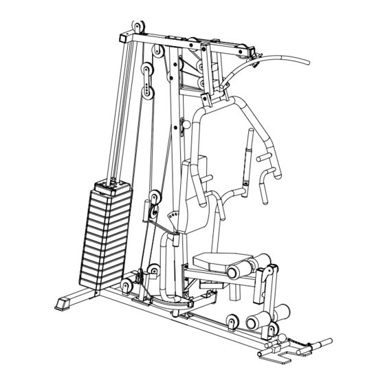
HOME GYM
50036
Advertisement
Table of Contents

Summary of Contents for Hyper Extension HOME GYM 50036
- Page 1 NOTE: Please read all instructions carefully before using this product www.hyper-extension.com HOME GYM Table of Contents 50036 Safety Notice Hardware Identifier Assembly Instruction Parts List Warranty Ordering Parts Model 50036 Retain This Manual for Reference OWNER'S MANUAL Please contact HUNTER LEISURE AUSTRALIA Should any questions arise at 1800-632-792 Warranty Service: If you require warranty service, please do not return the gym to the store.
-
Page 2: Table Of Contents
TABLE OF CONTENTS BEFORE YOU BEGIN..................2 IMPORTANT SAFETY NOTICES..............3 HARDWARE PACK………..…............... 4 ASSEMBLY INSTRUCTIONS................6 WEIGHT RESISTANCE CHART................25 PARTS LIST………………………………………………………………………….. 26 WARRANTY....................… 27 ORDERING PARTS..................27 BEFORE YOU BEGIN Thank you for selecting the 50036 HOME GYM by HYPER-EXTENSION. For your safety and benefit, read this manual carefully before using the machine. -
Page 3: Important Safety Notice
IMPORTANT SAFETY NOTICE PRECAUTIONS This exercise machine is built for optimum safety. However, certain precautions apply whenever you operate a piece of exercise equipment. Be sure to read the entire manual before you assemble or operate your machine. In particular, note the following safety precautions: 1. -
Page 4: Hardware Pack
HARDWARE PACK... - Page 5 HARDWARE PACK...
-
Page 6: Assembly Instruction
ASSEMBLY INSTRUCTION Tools Required Assembling the Machine: Two Adjustable Wrenches and Allen Wrenches NOTE: It is strongly recommended this machine be assembled by two or more people to avoid possible injury. STEP 1 (See Diagram 1) A.) Attach the Base Frame (#1) to the Rear Base Frame (#3). Secure them with two M10 x 70mm Carriage Bolts (#73), two ∅... - Page 7 STEP 2 (See Diagram 2) A.) Place two ∅ 60x25mm Rubber Bumpers (#60) on the Rear Base Frame (#3). Align the holes and insert Two Guide Rods (#18) through the holes into the Rear Base Frame. Secure each Guide Rod with one M10 x 25mm Allen Bolt (#75) and ∅ 10mm Washer (#87) from the bottom of Rear Base Frame.
- Page 8 DIAGRAM 2...
- Page 9 STEP 3 (See Diagram 3) A.) Attach the Upper Frame (#4) onto the two Guide Rods (#18). Secure each Guide Rod to the Upper Frame with on M10 x 25mm Allen Bolt (#75) and ∅ 10mm Washer (#87). DO NOT tighten the Nuts and Bolts yet. B.) Place the Upper Frame (#4) onto the top of the Vertical Frame (#5).
- Page 10 STEP 4 (See Diagram 4) A.) Attach the Leg Developer (#7) to the Seat Support Frame (#6). Align the holes and insert the Axle (#42) into the Leg Developer (#7) . Secure it with two M10 x 16mm Allen Bolt (#78), two ∅ 10mm Washers (#87). Do not over tighten the Bolts, ensure the Leg Developer is able to swivel.
- Page 11 STEP 5 (See Diagram 5) A.) Attach the Front Press (#11) to the pivot on the Front Press Base (#10). Align the holes and insert the Front Press Axle (#27) through the holes. B.) Secure each end of the Axle with one M10 x 20mm Allen Bolt (#79) and 10x33 Washer (#61).
- Page 12 STEP 6 (See Diagram 6) A.) Attach the Butterfly Base (#14) to the Vertical Frame (#5). Secure it with one 120 x 50mm Bracket (#26), two M10 x 90mm Carriage Bolts (#74), two ∅ 10mm Washers (#87), and two M10 Nylon Nuts (#88). B.) Insert the Right Butterfly (#20) into the right pivot on Butterfly Base.
- Page 13 STEP 7 (See Diagram 7) A.) Place the Seat Pad (#21) onto the Seat Post (#9). Secure it with two M8 x 40mm Allen Bolts (#77) and ∅ 8mm Washers (#86). B.) Insert the Seat Post (#9) into the opening on the Seat Support Frame (#6). Use a Lock Knob (#41) to obtain the desired height of Seat.
- Page 14 CABLE LOOP DIAGRAM...
- Page 15 STEP 8 (See Diagram 8 & Upper Cable Loop Diagram)
- Page 16 A.) Attach the 3980 Upper Cable (#31) to the opening on the front Upper Frame (#4). Make sure the ball stopper is underneath the Frame. Attach a Pulley (#43) to the Cable. Secure the Pulley with one M10 x 65mm Allen Bolt (#80), two Pulley Bushings (#56), and one M10 Nylon Nut (#88).
- Page 17 Upper Cable Loop Diagram...
- Page 19 STEP 9 (See Diagram 9 & Lower Cable Loop Diagram) A.) Attach the 3900mm Lower Cable (#33) to the opening on the Leg Developer (#7). Attach a Pulley to the opening. Secure it with one M10 x 45mm Allen Bolt (#81),two 10mm Washers (#87) and one M10 Nylon Nut (#88).
- Page 21 Lower Cable Loop Diagram STEP 10 (See Diagram 10 & Butterfly Cable Loop Diagram)
- Page 22 A.) Attach one end of the Butterfly Cable (#3 to the open slot on Right Butterfly (#20). B.) Draw the Cable to the open slot on the Butterfly Pulley Bracket (#17). Attach a Pulley to the open slot. Secure the Pulley with one M10 x Allen Bolt (#8 ), one L-shape Cable Bracket (# ), two Washers (#87), and one M10 Aircraft Nut (#8 ).
- Page 23 Butterfly Cable Loop Diagram...
- Page 24 STEP 11 (See Diagram11) A.) Connect the Lat Bar (#8) to the Upper Cable with two C-clips (#36) and one short Chain (#35). B.) Connect the Abdominal Strap (#93) to the mid Cable with a C-clip (#36) And One U-Shape Cable Connector (#66).
-
Page 25: Weight Resistance Chart
WEIGHT RESISTANCE CHART WEIGHT PLATE Station Low Pulley Lat Pull Butterfly Front Press AB Crunch Leg Developer WEIGHT PLATE Station Low Pulley Lat Pull Butterfly Front Press AB Crunch Leg Developer *Numbers are approximate. Actual weight may vary. *Value for butterfly is for each arm. -
Page 26: Part List
PART LIST KEY NO. DESCRIPTION KEY NO. DESCRIPTION Base Frame Foot Plate Axle Ф25x160 Handle Grip Rear Base Frame Short T-Shape Lock Pin Upper Frame Ф38xФ27 Sleeve Vertical Frame 50x25 End Cap Seat Support Frame □50 Square Cap Leg Developer Foam Roll End Cap Lat Bar Ф25 Flat End Cap... -
Page 27: Limited Warranty
HYPER-EXTENSION LIMITED WARRANTY The importer of this machine assures that this device was manufactured from high quality materials. A prerequisite for this warranty is the proper setup in accordance with the operating instructions provided. Improper use and / or incorrect transportation can render the warranty void. The limited warranty on this product is two years from the date of purchase.
Need help?
Do you have a question about the HOME GYM 50036 and is the answer not in the manual?
Questions and answers