
Related Manuals for Thunderbolt ARC-8050T2

Summary of Contents for Thunderbolt ARC-8050T2
-
Page 1: User Manual
Thunderbolt™ Product ARC-8050T2 (Thunderbolt 2 to 6Gb/s SAS RAID Storage) User Manual Version: 2.0 Issue Date: January, 2014... -
Page 2: Copyright And Trademarks
Manufacturer’s Declaration for CE Certification We confirm ARC-8050T2 has been tested and found comply with the requirements set up in the council directive on the approximation of the low of member state relating to the EMC Directive2004/108/EC. -
Page 3: Table Of Contents
2.4 Locations of the Storage Component ........16 2.4.1 Drive Tray LED Indicators ..........16 2.4.2 LCD Panel LED Indicators ..........17 2.4.3 Thunderbolt Port LED Indicators ........17 2.5 Setting Up RAID Storage ..........18 2.5.1 Physically Install RAID Storage and Drives ..... 18 2.5.2 Mac Users .............. - Page 4 4.2 McRAID Main Window ............48 4.3 Main Menu ..............49 4.4 Quick Function ..............49 4.5 Raid Set Functions ............50 4.5.1 Create Raid Set ............50 4.5.2 Delete Raid Set ............51 4.5.3 Expand Raid Set ............52 4.5.4 Offline Raid Set ............
- Page 5 4.7.5 Abort Cloning ............. 70 4.7.6 Set Disk To Be Failed ..........70 4.7.7 Activate Failed Disk ............ 70 4.7.8 Identify Enclosure ............71 4.7.9 Identify Drive ............71 4.8 System Controls ............. 72 4.8.1 System Config ............72 • System Beeper Setting ........... 72 •...
- Page 6 • Local IP address ............. 82 • Gateway IP address ............83 • Subnet Mask ..............83 • HTTP Port Number ............83 • Telnet Port Number ............83 • SMTP Port Number ............83 4.8.5 Alert By Mail Configuration ......... 83 4.8.6 SNMP Configuration ............
- Page 7 Volume Set ..............106 Ease of Use Features ............107 • Foreground Availability/Background Initialization ....107 • Online Array Roaming ........... 107 • Online Capacity Expansion ..........107 • Online RAID Level and Stripe Size Migration ....109 • Online Volume Expansion ..........110 High Availability ...............
-
Page 8: Introduction
Pro, and offers an additional Thunderbolt 2 port for daisy-chaining other peripherals. The Thunderbolt daisy-chaining allows connec- tion of up to six devices, so customers can connect ARC-8050T2 for massive amounts of video storage with a single Thunderbolt connection to their host computer. ARC-8050T2 can meet the de- mand of users when working with rich, ultra- high resolution media through Thunderbolt 2 interface. - Page 9 INTRODUCTION Enterprise-class Data Availability and Security ARC-8050T2 supports the hardware RAID 6 engine to allow two HDDs failures without impact the existing data and performance. It allows users to hot swap drive in the event of a drive failure with zero downtime. Its high data availability and protection de- rives from many advanced RAID features on ARC-8050T2 RAID box design.
-
Page 10: Features
• SSD automatic monitor clone (AMC) support • Complete configuration management suite - McRAID manager – browser-based management tool (LAN or Thunderbolt) - Push Buttons and LCD Display panel for setup and status - Command Line Interface (CLI) – scriptable configuration tool - API libraries support –... -
Page 11: Product Features
Support a battery backup option that protects all data in cache memory in the event of unexpected power outage. Intelligent power On/Off Turn ARC-8050T2 power in unison with the host function computer power status for data integrity. Front Panel LCD and Buttons Easy access for configuration and status report. -
Page 12: Installation
ARC-8050T2 RAID storage is packed inside an anti-static bag between two sponge sheets. Remove it and inspect it for dam- age. If the ARC-8050T2 RAID storage appears damaged, or if any items of the contents listed below are missing or damaged, please contact your dealer or distributor immediately. -
Page 13: Summary Of Raid Storage Setup Steps
Step 3. Configure RAID Volumes (Chapter 2.5.2.2) 1. Double-click on the “MRAID” icon on the desktop. 2. Double-click on the “ArcHTTP64”. 3. Locate “ARC-8050T2 Web Management” and launch the McRAID storage manager. 4. Login User Name “admin” and the Password “0000”. - Page 14 Step 3. Configure RAID Volumes (Chapter 2.5.3.2) 1. Double-click on the “MRAID” icon on the desktop. 2. Double-click on the “ArcHTTP64”. 3. Locate “ARC-8050T2 Web Management” and launch the McRAID storage manager. 4. Login User Name “admin” and the Password “0000”.
-
Page 15: Raid Storage View
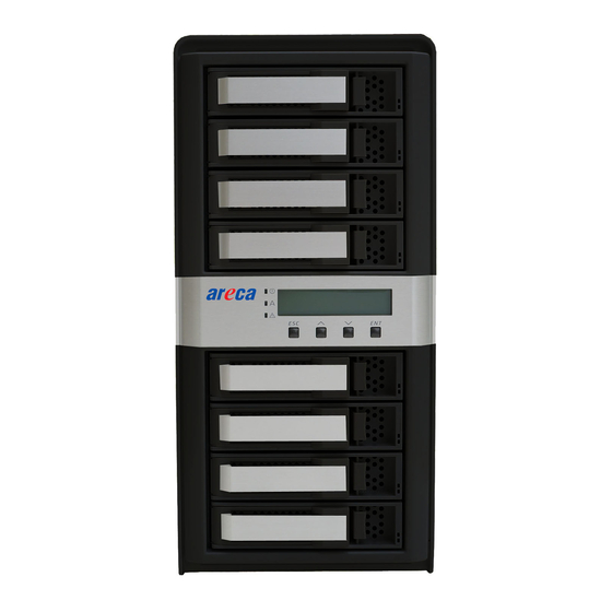
1. Disk Activity LED 4. Thunderbolt Port1 2. Disk Fault/Link LED 5. Thunderbolt Port2 3. LCD Panel with Keypad 6. Thunderbolt Port1 Link LED 7. Thunderbolt Port2 Link LED 8. System Fan1 9. LAN Port (For McRAID Web Manager) 10. Reset Button 11. -
Page 16: Locations Of The Storage Component
INSTALLATION 2.4 Locations of the Storage Component The following components come with LEDs that inform ARC-8050T2 RAID storage managers about the operational status. 2.4.1 Drive Tray LED Indicators Figure 2-1, Activity/Fault LED The following table describes the RAID storage disk drive tray LED behavior. -
Page 17: Lcd Panel Led Indicators
(Red) storage and all its components more component failure/Ur- are operating correctly. gent events have occurred. 2.4.3 Thunderbolt Port LED Indicators Figure 2-3, Thunderbolt Ports LED The following table describes the ARC-8050T2 SAS RAID storage Thunderbolt port link LED behavior. -
Page 18: Setting Up Raid Storage
There is a proper DisplayPort to DVI connection on that Thunderbolt port. 2.5 Setting Up RAID Storage Setting up your ARC-8050T2 RAID storage involves these main steps: • Physically Install the RAID Storage and Drives • Install the MRAID Software •... - Page 19 Figure 2-5, Sliding Drive Tray into Enclosure Step 2. Connecting RAID Storage to Thunderbolt Ports Thunderbolt connectors are provided on the back of the ARC-8050 RAID storage for connecting the array to Thunderbolt host and next Thunderbolt devices. There are two Thunderbolt connectors on the rear of ARC-8050 RAID storage.
- Page 20 Thunderbolt capable computer. The additional port may be used to daisy chain compatible computer peripherals, such as hard drives, monitors, and much more. A single Thunderbolt port supports hubs as well as a daisy chain of up to seven Thun-...
- Page 21 ARC-8050 RAID stor- age. 2. ARC-8050 RAID storage will automatically turn on when host computer power on status is received from the thunderbolt cable. It takes about 30 seconds to fully start up the RAID stor- age.
-
Page 22: Mac Users
This section describes detailed instructions for installing the Areca Mac driver & utility for the ARC-8050 on your Apple Thunderbolt capable machine. You must have administrative level permissions to install Mac OS X driver & utility. This can be done in just a few steps! 1. - Page 23 INSTALLATION 2. Double-click on the zipped file that comes from the website or resides at <CDROM>\packages\MacOS to add the installer on the Finder. 3. Launch the installer by double-clicking the install_mraid on the Finder. The MRAID Installer opens. Click on the "Next" button to begin the installation.
- Page 24 INSTALLATION • ArcHTTP has to be installed for GUI RAID console (MRAID storage manager) to run. It also runs as a service or daemon in the background that allows capturing of events for mail and SNMP traps notification. Refer to the Chapter 5 ArcHTTP Configuration on ARC-8050 user manual, for details about the mail and SNMP traps configuration.
- Page 25 INSTALLATION 8. A program bar appears that measures the progress of the driver installation. 9. When this screen shows, you have completed the driver installation and click on the "Next" button to continue.
-
Page 26: Configure Raid Volumes
RAID storage. Your ARC- 8050 RAID storage can be configured by one of the following methods: 1. McRAID Storage Manager from ArcHTTP. (Thunderbolt port) 2. McRAID Storage Manager Through LAN port. 3. LCD Panel with Keypad. - Page 27 INSTALLATION • Method 1: McRAID Storage Manager From ArcHTTP Start McRAID Storage Manager – Browser Edition There is one “MRAID” icon showing on your desktop. Double- click on the “MRAID” icon to locate your ArcHTTP utility and CLI program file folder. When you double-click on the “ArcHTTP64”, it shows all RAID storages available on the system and create an individual RAID storage icon located on left column of the “ArcHTTP Con-...
- Page 28 INSTALLATION Click on the “Quick Create” in the main menu, your volume is automatically configured based on the number of disks in your system. You can create a RAID set associated with exactly one volume set. The user can change the Raid Level, Capacity, Initialization Mode, and Stripe Size.
-
Page 29: Format Raid Volumes
INSTALLATION • Method 3: LCD Panel with Keypad You can use LCD front panel and keypad function to simply create the RAID volume. The LCD status panel also informs you of the disk array’s current operating status at a glance. The LCD configuration is described in a separate manual: ARC-8050_LCD manual. - Page 30 INSTALLATION 2. In the Partition Layout column, click on the “Current” to show the drop-down menu and select the number of parti- tions that you want your RAID storage to have. Each partition will appear as a separate drive on your computer. 3.
-
Page 31: Make A Bootable Raid Volume
8050 RAID storages volume(s) be properly unmounted from the computer prior to turning off the RAID storage or safely removing the Thunderbolt interface cable. 1. Drag RAID storage volume(s) icon to the trash. The Trash will turn into an Eject arrow. This will assure that all data is properly cleared from the system memory before the volume is removed. -
Page 32: Windows Users
INSTALLATION 2. When the volume icon disappears from the desktop, RAID storage can be disconnected from the computer. 2.5.3 Windows Users 2.5.3.1 Install the MRAID Software This section describes how to install the MRAID software to your operating system. The software installation includes device driver, ArcHTTP and CLI utility. - Page 33 INSTALLATION 5. When the License Agreement screen appears, read and agree to the license information; then let the InstallShield Wizard guide you through the installation process. 6. On the Setup Type screen, use the settings to specify these things: and click on the “Next” button to continue.
- Page 34 INSTALLATION • “Complete” to install driver, ArcHTTP and CLI utility at once, check the first box. • “Custom” to install special components and change the pro- gram directory. When this “Custom” check box is checked, go to the Custom Setup screen. 6-1.
- Page 35 INSTALLATION 7. When you reach the installation page, click on the “Install” button to continue. 8. A program bar appears that measures the progress of the driver installation. When this screen completes, you have completed the MRAID installation. If you have no ARC-8050 RAID storage unit yet con- nected or powered on, a “MRAID Installer Information”...
-
Page 36: Configure Raid Volumes
“2.5.3.2 Configure RAID Volumes” section to configure the volume. Note: “For Windows, Install Driver First” For Windows PC: the Thunderbolt certified device driver must be installed before plugging in the device for it to function properly. 2.5.3.2 Configure RAID Volumes There are often multiple ways to accomplish the same configu- ration and maintenance tasks for your RAID storage. - Page 37 INSTALLATION • Method 1: McRAID Storage Manager From ArcHTTP Start McRAID Storage Manager – Browser Edition Right-click on the “Start” menu and choose “Programs”. Double-click on the “MRAID” program icon to start the ArcHTTP utility (From the Start menu, choose Programs > MRAID >...
- Page 38 INSTALLATION Click on the “Quick Create” in the main menu, your volume is automatically configured based on the number of disks in your system. You can create a RAID set associated with exactly one volume set. The user can change the Raid Level, Capacity, Initialization Mode, and Stripe Size.
-
Page 39: Format Raid Volumes
Windows Explorer. 2.5.3.4 Unmounting RAID Volumes To avoid possible data corruption, Areca recommends that ARC- 8050 RAID storages volume(s) be properly unmounted from the computer prior to turning off the RAID storage or safely removing the Thunderbolt interface cable. - Page 40 Click the "Start" button, click "Computer", right-click the device you want to remove, and then click "Eject". 2. Windows will display a notification telling you it's safe to remove the Thunderbolt storage volume. Now you can unplug the Thunderbolt cable.
-
Page 41: Archttp Configuration
HTTP Port#: Value 1~65535. Display HTTP Connection Information To Console: Select “Yes" to show Http send bytes and receive bytes information in the console. Scanning PCI Device: Select “Yes” for ARC-8050T2 RAID storage unit. Scanning RS-232 Device: No. Scanning Inband Device: No. -
Page 42: Mail (Alert By Mail) Configuration
ArcHTTP Configuration • Mail (Alert by Mail) Configuration Many users require that email notifications be sent to the appropriate administrators when an alert is detected. To set up your mail servers, click on the the “Mail Configuration” link. The “SMTP Server Configurations”... -
Page 43: Snmp Traps Configuration
ArcHTTP Configuration 2. Mail Address Configurations Sender Name: Enter the sender name that will be shown in the outgoing mail. Ex: RaidController_1. Mail address: Enter the sender email that will be shown in the outgoing mail, but don’t type IP to replace domain name. Ex: RaidController_1@areca.com.tw. - Page 44 ArcHTTP Configuration agent on the host. If SNMP manager requests to query the SNMP information from RAID storage, please refer the Appendix C "SNMP Operation & Installation". The “SNMP traps Configuration” menu will show as following: When you open the SNMP traps configuration page, you will see the following settings: 1.
-
Page 45: Rescan Device Configuration
ArcHTTP Configuration Note: Event Notification Table refer to Appendix D. After you confirm and submit configurations, you can use "Generate Test Event" feature to make sure these settings are correct. • Rescan Device Configuration Let’s assume you’ve put all Areca RAID storages to a system. The ArcHTTP scans the RAID storages on the system and create an individual RAID storage icon located on left column of the "ArcHTTP Configurations"... -
Page 46: Web Browser-Based Configuration
WEB BROWSER-BASED CONFIGURATION 4. Web Browser-based Configuration If you need to use a RAID volume from ARC-8050T2 RAID storage unit, you must first create a RAID volume by using LCD or McRAID storage manager. This chapter shows you how to set up RAID volumes using the McRAID storage manager application on a computer with an ARC-8050T2 RAID storage. -
Page 47: Start-Up Mcraid Storage Manager
RAID storage web browser McRAID storage manager. Locate “ARC-8050T2 Web Management” and launch the select- ed McRAID RAID storage manager. Enter RAID storage default User Name “admin” and the Password “0000” when the login page prompted for it. -
Page 48: Mcraid Storage Manager Through Lan Port (Out-Of-Band)
WEB BROWSER-BASED CONFIGURATION • McRAID Storage Manager Through LAN Port (Out-of-Band) ARC-8050T2 RAID storage also offers an alternative out-of- band method for McRAID storage manager. User can access the built-in configuration without running the ArcHTTP proxy server on the host system. The web browser-based McRAID storage manager is a HTML-based application, which utilizes the brows- er installed on your remote system. -
Page 49: Main Menu
WEB BROWSER-BASED CONFIGURATION • To display RAID set information, move the mouse cursor to the desired RAID set number, then click on it. The RAID set infor- mation will be displayed. • To display volume set information, move the mouse cursor to the desired volume set number, then click it. -
Page 50: Raid Set Functions
WEB BROWSER-BASED CONFIGURATION The number of physical drives in the RAID storage determines the Raid Levels that can be implemented with the RAID set. You can create a RAID set associated with exactly one volume set. The user can change the Raid Level, Capacity, Initialization Mode, and Stripe Size. -
Page 51: Delete Raid Set
WEB BROWSER-BASED CONFIGURATION alphanumeric characters to define a unique identifier for a RAID set. The default RAID set name will always appear as “Raid Set #”. Click the “Confirm The Operation” check box and click on the “Submit” button on the screen; the RAID set will start to initialize. If you have available disk member, you can repeat above proce- dures to define another RAID sets. -
Page 52: Expand Raid Set
WEB BROWSER-BASED CONFIGURATION 4.5.3 Expand Raid Set Instead of deleting a RAID set and recreating it with additional disk drives, the “Expand Raid Set” function allows the users to add disk drives to the RAID set that have already been created. To expand a RAID set: 1. -
Page 53: Offline Raid Set
WEB BROWSER-BASED CONFIGURATION Note: 1. Once the “Expand Raid Set” process has started, user can not stop it. The process must be completed. 2. If a disk drive fails during RAID set expansion and a hot spare is available, an auto rebuild operation will occur after the RAID set expansion completes. -
Page 54: Activate Incomplete Raid Set
WEB BROWSER-BASED CONFIGURATION 4.5.6 Activate Incomplete Raid Set If one of the disk drives is removed in power off state, the RAID set state will change to “Incomplete State”. If the user wants to continue to operate the controller without power-off the RAID storage, the user can use the “Activate Incomplete Raid Set”... -
Page 55: Delete Hot Spare
WEB BROWSER-BASED CONFIGURATION The “Create Hot Spare” gives you the ability to define a global or dedicated hot spare. Unlike “Global Hot Spare” which can be used with any RAID sets, “Dedicated Hot Spare” can only be used with a specific RAID set or Enclosure. When a disk drive fails in the RAID set or enclosure with a dedicated hot spare is pre-set, data on the disk drive is rebuild automatically on the dedicated hot spare disk. -
Page 56: Volume Set Functions
WEB BROWSER-BASED CONFIGURATION Caution: Please contact us to make sure if you need to use rescue function. Improperly usage may cause configuration corruption. 4.6 Volume Set Functions A volume set is seen by the host system as a single logical device. It is organized in a RAID level with one or more physical disks. -
Page 57: Create Volume Set (0/1/10/3/5/6)
Support, Initialization Mode, Strip Size, Cache Mode, Tagged Command Queuing, and SCSI Channel/SCSI ID/SCSI Lun. • Volume Name The default volume name will always appear as “ARC-8050T2- VOL”. You can rename the volume set providing it does not exceed the 15 characters limit. •... -
Page 58: Initialization Mode
WEB BROWSER-BASED CONFIGURATION It keeps the volume size with max. 2TB limitation. -64bit LBA This option uses 16 bytes CDB instead of 10 bytes. The maxi- mum volume capacity is up to 512TB. This option works on different OS which supports 16 bytes CDB. -4K Block It changes the sector size from default 512 bytes to 4k bytes. -
Page 59: Cache Mode
ROC and operat- ing at full channel speeds. The hardware encryption does not impact the performance of ARC-8050T2 RAID controller and can implement on any kinds of HDD that is transparent to the user, the OS, and applications. -
Page 60: Tagged Command Queuing
WEB BROWSER-BASED CONFIGURATION the algorithm to behave slightly differently, so the increasing key sizes not only offer a larger number of bits with which you can scramble the data, but also increase the complexity of the cipher algorithm. ARC-1882 adapters provide five new key options in the ‘Full Volume Encryption:”Disable’, “256Bit key, Password”, “256Bit key, AES”, “128Bit key, Password”, “128Bit key, AES”. -
Page 61: Create Raid30/50/60 (Volume Set 30/50/60)
WEB BROWSER-BASED CONFIGURATION 4.6.2 Create Raid30/50/60 (Volume Set 30/50/60) To create 30/50/60 volume set from RAID set group, move the cursor bar to the main menu and click on the “Create Raid30/50/60” link. The “Select The Raid Set To Create Volume On It”... -
Page 62: Modify Volume Set
WEB BROWSER-BASED CONFIGURATION Click a volume set number and the “Confirm The Operation” check box and then click the “Submit” button to delete the vol- ume set. 4.6.4 Modify Volume Set To modify a volume set from a RAID set: 1. -
Page 63: Volume Growth
WEB BROWSER-BASED CONFIGURATION 4.6.4.1 Volume Growth Use “Expand Raid Set" function to add disk to a RAID set. The additional capacity can be used to enlarge the last volume set size or to create another volume set. The “Modify Volume Set” function can support the “Volume Modification”... -
Page 64: Volume Write Protection
WEB BROWSER-BASED CONFIGURATION Note: 1. If the volume is RAID level 30, 50, or 60, you can not change the volume to another RAID level. If the volume is RAID level 0, 1, 10(1E), 3, 5, or 6, you can not change the volume to RAID level 30, 50, or 60. -
Page 65: Schedule Volume Check
WEB BROWSER-BASED CONFIGURATION 4.6.6 Schedule Volume Check A volume check is a process that verifies the integrity of redun- dant data. To verify RAID 3, 5, 6, 30, 50 or 60 redundancy, a volume check reads all associated data blocks, computes parity, reads parity, and verifies that the computed parity matches the read parity. -
Page 66: Download Volume Key File
4.6.8 Download Volume Key File Get the key file which was generated by CLI “vsf genkey” com- mand or API code for your ARC-8050T2. You can follow below steps to download volume key file. 1. To download volume key file into the firmware, move the mouse cursor to “Download Volume Key file”... -
Page 67: Physical Drive
WEB BROWSER-BASED CONFIGURATION 4.7 Physical Drive Choose this option to select a physical disk from the main menu and then perform the operations listed below. 4.7.1 Create Pass-Through Disk To create pass-through disk, move the mouse cursor to the main menu and click on the “Create Pass-Through”... -
Page 68: Delete Pass-Through Disk
WEB BROWSER-BASED CONFIGURATION When the “Enter Pass-Through Disk Attribute” screen appears, modify the drive attribute values, as you want. After you com- plete the selection, mark the check box for “Confirm The Opera- tion” and click on the “Submit” button to complete the selection action. -
Page 69: Clone And Replace
WEB BROWSER-BASED CONFIGURATION Clone Disk Procedure 1. Select one of the members as the “Clone Source” (status indi cated as Raid Set #) by clicking on the appropriate check box. 2. Select a “Clone Target” (status indicated as Free or Hot Spare) by clicking on the appropriate check box. -
Page 70: Abort Cloning
WEB BROWSER-BASED CONFIGURATION 4.7.5 Abort Cloning Use this function to stop the ongoing clone disk action. 4.7.6 Set Disk To Be Failed It sets a normal working disk as “failed” so that users can test some of the features and functions. 4.7.7 Activate Failed Disk It forces the current “failed”... -
Page 71: Identify Enclosure
WEB BROWSER-BASED CONFIGURATION Followings are considered as “Removed-Disk”: 1. Manually removed by user. 2. Losing PHY connection due to bad connector, cable, backplane. 3. Losing PHY connection due to disk fail. Basically, in the eyes of the controller, the disk suddenly disap- pears due to whatever reason. -
Page 72: System Controls
WEB BROWSER-BASED CONFIGURATION 4.8 System Controls 4.8.1 System Config To set the RAID system function, move the cursor to the main menu and click the “System Controls” link. The “Raid System Function” menu will show all items, and then select the desired function. -
Page 73: Sata Ncq Support
WEB BROWSER-BASED CONFIGURATION • SATA NCQ Support The controller supports both SAS and SATA disk drives. The SATA NCQ allows multiple commands to be outstanding within a drive at the same time. Drives that support NCQ have an internal queue where outstanding commands can be dynami- cally rescheduled or re-ordered, along with the necessary tracking mechanisms for outstanding and completed portions of the workload. -
Page 74: Max Command Length
WEB BROWSER-BASED CONFIGURATION • Max Command Length Max Command Length is used to set a "best" IO size for the RAID storage. • Auto Activate Incomplete Raid When some of the disk drives are removed in power off state or boot up stage, the RAID set state will change to “Incom- plete State”. -
Page 75: Disk Capacity Truncation Mode
WEB BROWSER-BASED CONFIGURATION triggers a rebuilding for the Degraded RAID set/Volume. “Disable” – it will not trigger rebuilding regardless what sort of disk plugging in. When “Disable” and/or “Blank Disk Only” is selected, the re-inserted/previously removed disk will be iden- tified as a disk in a separate RAID set with duplicated RAID- set# and with all the rest of RAID members missing. -
Page 76: Smart Polling Interval
WEB BROWSER-BASED CONFIGURATION “Failed The Drive If Hot Sapre Exist” – controllers kill off the SMART fail disk if hot sapre dive is existed. “Alert” – it will trigger alert when there happens a SMART fail drive. • Smart Polling Interval Besides the scheduled volume check, user can define the Smart Pulling Interval to pull the SMART status of each disk. -
Page 77: Timeout Setting
WEB BROWSER-BASED CONFIGURATION drive from the array during this period. Default value is manu- facture setting. You can select between 5, 6 and 7 second. This feature is used to setup the HDD internal timeout value. • Timeout Setting Disk time-out is a registry setting that defines the time that RAID controller will wait for a hard disk to respond to a com- mand. -
Page 78: Amount Of Read Ahead
WEB BROWSER-BASED CONFIGURATION • Amount of Read Ahead Read-Ahead data is buffered in the RAID controller cache, however, thereby cutting down on the amount of I/O traffic to the disk. The Amount of Read Ahead defines how many data of reading at a time, making more efficient use of the RAID storage. -
Page 79: Read Performance Margin
WEB BROWSER-BASED CONFIGURATION and Mode 3. Default value is “Disabled”. Our controller cache uses LRU method; there have no special memory capacity re- served for read or write. The Mode 1, 2 and 3 are used to de- fine the command sorting method. The default sorting method is helpful for normal applications, but not useful for AV ap- plications, so we have defined three different sorting methods for these special applications. -
Page 80: Hdd Power Management
WEB BROWSER-BASED CONFIGURATION 4.8.3 HDD Power Management Areca has automated the ability to manage HDD power based on usage patterns. The “HDD Power Management” allows you to choose a “Stagger Power On Control”, “Low Power Idle”, “Low RPM” and completely “Spins Down Idle HDD”. It is designed to reduce power consumption and heat generation on idle drives. -
Page 81: Time To Hdd Low Power Idle
WEB BROWSER-BASED CONFIGURATION values can be selected from 0.4 to 6 seconds per step which powers up one drive. • Time to Hdd Low Power Idle This option delivers lower power consumption by automati- cally unloading recording heads during the setting idle time. The values can be selected “Disabled”... -
Page 82: Dhcp Function
WEB BROWSER-BASED CONFIGURATION patches required. To configure the RAID controller Ethernet port, move the cursor bar to the main menu and click on the “System Controls” link. The “System Controls” menu will show all items. Move the cursor bar to the “Ethernet Configuration” item, and then select the desired function. -
Page 83: Gateway Ip Address
WEB BROWSER-BASED CONFIGURATION • Gateway IP address A gateway is a node (a router) on a TCP/IP network that serves as an access point to another network. A default gate- way is the node on the computer network that the network software uses when an IP address does not match any other routes in the routing table. -
Page 84: Snmp Configuration
WEB BROWSER-BASED CONFIGURATION The firmware contains a SMTP manager monitoring all system events. Single or multiple user notifications can be sent via “Plain English” e-mails with no software required. (Please refer to SMTP Sever Configuration, Mail Address Configuration and Event Notifi- cation Configuration on chapter 3 “ArcHTTP Configuration”... -
Page 85: Ntp Sever Address
WEB BROWSER-BASED CONFIGURATION Note: NTP feature works through onboard Ethernet port. So you must make sure that you have connected onboard Ethernet port. • NTP Sever Address The most important factor in providing accurate, reliable time is the selection of NTP servers to be used in the configuration file. -
Page 86: Generate Test Event
WEB BROWSER-BASED CONFIGURATION Select this option to view the system events information: Time, Device, Event Type, Elapse Time and Errors. The RAID storage does not have a built-in real time clock. The time information is the relative time from the system time setting. The maximum event no. -
Page 87: Modify Password
WEB BROWSER-BASED CONFIGURATION 4.8.11 Modify Password To set or change the RAID storage password, select “System Con- trols” from the menu and click on the “Modify Password” link. The “Modify System Password” screen appears. The password option allows user to set or clear the RAID stor- age’s password protection feature. -
Page 88: Information
Chip Information” link. The RAID storage “SAS Chip Information” screen appears. User can click on “controller: Areca ARC-8050T2” item on the “SAS Chip Information” screen. It will show statistic page for ports on the ROC controller. Click on the “Clear Error Log” to re-... -
Page 89: System Information
WEB BROWSER-BASED CONFIGURATION 4.9.3 System Information To view the RAID storage’s system information, move the mouse cursor to the main menu and click on the “System Information” link. The RAID storage “RAID Subsystem Information” screen ap- pears. Use this feature to view the RAID storage’s system infor- mation. -
Page 90: Upgrading Flash Rom Update Process
ARC8050FIRM.BIN:→ RAID kernel program ARC8050MBR0.BIN:→ Master Boot Record for supporting Dual Flash Image in the ARC-8050T2 6Gb/s SAS RAID storage README.TXT contains the history information of the software code change in the main directory. Read this file first to make sure you are upgrading to the proper binary file. - Page 91 The web browser-based McRAID storage manager can be accessed through the in-band Thunderbolt port or out-of-band LAN port. The in-band method uses the ArcHTTP proxy server to launch the McRAID storage manager. The out-of-band method allows local or...
- Page 92 APPENDIX Controller with onboard LAN port, you can directly plug an Ethernet cable to the controller LAN port. After network connected, you can find the current IP address in the LCD panel. From a remote pc, you can directly open a web browser and enter the IP address.
-
Page 93: Battery Backup Module
Appendix B Battery Backup Module (ARC-6120BA-T021) ARC-8050T2 RAID storage operates using cache memory. The Bat- tery Backup Module is an add-on module that provides power to the RAID storage cache memory in the event of a power failure. The BBM monitors the write back cache on the RAID storage, and provides power to the cache memory if it contains data not yet written to the hard drives when power failure occurs. -
Page 94: Installation
APPENDIX B-3 Installation 1. Make sure all power to the RAID storage is disconnected. 2. Install the “six eaves copper pillars” on the three mounting position (NH1, NH2 and NH3) and secures it using round head screws. 3. Connector J1 is available for the optional battery backup module. - Page 95 APPENDIX B-4 Battery Backup Capacity Battery backup capacity is defined as the maximum duration of a power failure for which data in the cache memory can be maintained by the battery. The BBM’s backup capacity duration can retain the cache content for a limited interval (typically 72 hours).
- Page 96 • Operating Temperature Temperature: 0 C to +40 Humidity: 45-85%, non-condensing • Storage Temperature Temperature: -40 C to 60 Humidity: 45-85%, non-condensing • Electrical Input Voltage +3.6VDC • On Board Battery Capacity 1880mAH (1 * 1880mAH) for ARC-8050T2 RAID storage...
-
Page 97: Snmp Operation & Installation
APPENDIX Appendix C SNMP Operation & Installation C-1 Overview McRAID storage manager includes a firmware-embedded Simple Network Management Protocol (SNMP) agent and SNMP Extension Agent for the Areca RAID controller. An SNMP-based management application (also known as an SNMP manager) can monitor the disk array. - Page 98 APPENDIX Manager Application Managed Resource Definition Service Layer and Protocols Physical Managed Object C-3 SNMP Installation Perform the following steps to install the Areca RAID control- ler SNMP function into the SNMP manager. The installation of the SNMP manager is accomplished in several phases: Step 1.
- Page 99 Step 3. SNMP Service Method With Areca series RAID controllers, there are 2 service methods to get SNMP: in-band Thunderbolt port and onboard NIC. 1. Service Method-1: Using in-band Thunderbolt port (ArcHTTP proxy server) Pay attention to these: •...
- Page 100 APPENDIX To enable the controller to send the SNMP traps to client SNMP manager using the IP address assigned to the operating system, such as Net-SNMP manager, you can simply use the SNMP function on the ArcHTTP proxy server utility. To enable the RAID controller SNMP traps sending function, configure the “SNMP Traps Configuration”...
- Page 101 APPENDIX The firmware-embedded SNMP agent manager monitors all system events and the SNMP function becomes functional with no agent software required. When you open the "SNMP Configuration" link, you will see the following settings: 1. SNMP Trap Configurations Enter the SNMP Trap IP Address. 2.
-
Page 102: Event Notification Configurations
APPENDIX Appendix D Event Notification Configurations The controller classifies disk array events into four levels depending on their severity. These include level 1: Urgent, level 2: Serious, level 3: Warning and level 4: Information. The level 4 covers notifica- tion events such as initialization of the controller and initiation of the rebuilding process;... -
Page 103: Volume Event
APPENDIX PassThrough Disk Inform Pass Through Disk Created created PassThrough Disk Inform Pass Through Disk Modified modified PassThrough Disk Inform Pass Through Disk Deleted deleted B. Volume Event Event Level Meaning Action Start Initialize Warning Volume initialization has started Start Rebuilding Warning Volume rebuilding has started Start Migrating... -
Page 104: Raid Set Event
APPENDIX C. RAID Set Event Event Level Meaning Action Create RaidSet Warning New RAID set created Delete RaidSet Warning Raidset deleted Expand RaidSet Warning Raidset expanded Rebuild RaidSet Warning Raidset rebuilding RaidSet Urgent Raidset degraded Replace HDD Degraded D. Hardware Monitor Event Event Level Meaning... - Page 105 APPENDIX Telnet Log Serious a Telnet login detected InVT100 Log In Serious a VT100 login detected API Log In Serious a API login detected Lost Rebuilding/ Urgent Some rebuilding/ Reinserted the missing member MigrationLBA migration raidset disk back, controller will member disks continued the incompleted missing before power...
-
Page 106: Raid Concept
APPENDIX Appendix E RAID Concept RAID Set A RAID set is a group of disks connected to a RAID controller. A RAID set contains one or more volume sets. The RAID set itself does not define the RAID level (0, 1, 1E, 3, 5, 6, 10, 30, 50 60, etc);... -
Page 107: Ease Of Use Features
APPENDIX In the illustration, volume 1 can be assigned a RAID level 5 of operation while volume 0 might be assigned a RAID level 1E of operation. Alternatively, the free space can be used to create vol- ume 2, which could then be set to use RAID level 5. Ease of Use Features Foreground Availability/Background Initialization •... - Page 108 APPENDIX RAID set. Then, data on the existing volume sets (residing on the newly expanded RAID set) is redistributed evenly across all the disks. A contiguous block of unused capacity is made available on the RAID set. The unused capacity can be used to create additional volume sets.
-
Page 109: Online Raid Level And Stripe Size Migration
APPENDIX • Online RAID Level and Stripe Size Migration For those who wish to later upgrade to any RAID capabilities, a system with online RAID level/stripe size migration allows a simplified upgrade to any supported RAID level without having to reinstall the operating system. The RAID controllers can migrate both the RAID level and stripe size of an existing volume set, while the server is on- line and the volume set is in use. -
Page 110: Online Volume Expansion
APPENDIX transitions from migrating state to (migrating+degraded) state. When the migration is completed, the volume set tran- sitions to degraded mode. If a global hot spare is present, then it further transitions to rebuilding state. Online Volume Expansion • Performing a volume expansion on the controller is the pro- cess of growing only the size of the latest volume. -
Page 111: Hot-Swap Disk Drive Support
APPENDIX is not a member of any RAID set. If a disk drive used in a volume set fails, then the hot spare will automatically take its place and he data previously located on the failed drive is reconstructed on the hot spare. Dedicated hot spare is assigned to serve one specified RAID set. -
Page 112: Auto Rebuilding
APPENDIX In the normal status, the newly installed drive will be recon- figured an online free disk. But, the newly-installed drive is automatically assigned as a hot spare if any hot spare disk was used to rebuild and without new installed drive replaced it. -
Page 113: High Reliability
APPENDIX RAID controller allows user to choose the task priority (Ultra Low (5%), Low (20%), Medium (50%), High (80%)) to bal- ance volume set access and background tasks appropriately. For high array performance, specify an Ultra Low value. Like volume initialization, after a volume rebuilds, it does not re- quire a system reboot. -
Page 114: Consistency Check
APPENDIX a recoverable read error, the correct data will be transferred to the host and that location will be tested by the drive to be certain the location is not defective. If it is found to have a defect, data will be automatically relocated, and the defective location is mapped out to prevent future write attempts. -
Page 115: Recovery Rom
RAID controller firmware is stored on the flash ROM and is ex- ecuted by the I/O processor. The firmware can also be updat- ed through the RAID controllers Thunderbolt port or Ethernet port without the need to replace any hardware chips. During... -
Page 116: Understanding Raid
APPENDIX Appendix F Understanding RAID RAID is an acronym for Redundant Array of Independent Disks. It is an array of multiple independent hard disk drives that provides high performance and fault tolerance. The RAID controller imple- ments several levels of the Berkeley RAID technology. An appro- priate RAID level is selected when the volume sets are defined or created. -
Page 117: Raid 1
APPENDIX RAID 1 RAID 1 is also known as “disk mirroring”; data written on one disk drive is simultaneously written to another disk drive. Read performance will be enhanced if the array controller can, in paral- lel, access both members of a mirrored pair. During writes, there will be a minor performance penalty when compared to writing to a single disk. -
Page 118: Raid 10(1E)
APPENDIX RAID 10(1E) RAID 10(1E) is a combination of RAID 0 and RAID 1, combining stripping with disk mirroring. RAID Level 10 combines the fast performance of Level 0 with the data redundancy of level 1. In this configuration, data is distributed across several disk drives, similar to Level 0, which are then duplicated to another set of drive for data protection. -
Page 119: Raid 5
APPENDIX RAID 5 RAID 5 is sometimes called striping with parity at byte level. In RAID 5, the parity information is written to all of the drives in the controllers rather than being concentrated on a dedicated parity disk. If one drive in the system fails, the parity information can be used to reconstruct the data from that drive. -
Page 120: Raid 6
APPENDIX RAID 6 RAID 6 provides the highest reliability. It is similar to RAID 5, but it performs two different parity computations or the same compu- tation on overlapping subsets of the data. RAID 6 can offer fault tolerance greater than RAID 1 or RAID 5 but only consumes the capacity of 2 disk drives for distributed parity data. -
Page 121: Single Disk (Pass-Through Disk)
APPENDIX Important RAID level 00, 100, 30, 50 and 60 can support up to eight RAID set. If volume is RAID level 00, 100, 30, 50, or 60, you can’t change the volume to another RAID level. If volume is RAID level 0, 1, 10(1E), 3, 5, or 6, you can’t change the volume to RAID level 00, 100, 30, 50, or 60. -
Page 122: Summary Of Raid Levels
APPENDIX Summary of RAID Levels ARC-8050T2 Thunderbolt RAID storage supports RAID Level 0, 1, 10(1E), 3, 5, 6, 30, 50 and 60. The following table provides a summary of RAID levels. RAID Level Comparision RAID Description Disks Data Availability Level... - Page 123 APPENDIX RAID 30 is a combination multiple Up to one disk RAID 3 volume sets with RAID 0 failure in each (striping) sub-volume RAID 50 is a combination multiple Up to one disk RAID 5 volume sets with RAID 0 failure in each (striping) sub-volume...
Need help?
Do you have a question about the ARC-8050T2 and is the answer not in the manual?
Questions and answers