Table of Contents
Advertisement
Quick Links
Models FL3100H/FL3101H
UV/IR and UV only
Flame Detectors
The information and technical data disclosed in
this document may be used and disseminated
only for the purposes and to the extent
specifically authorized in writing by General
Monitors.
Instruction Manual
DATE 01-10
General Monitors reserves the right to change
published specifications and designs without
prior notice.
MANFL3100H/3101H
Part No.
MANFL3100/3101H
Revision
B/01-10
Advertisement
Table of Contents

Subscribe to Our Youtube Channel
Summary of Contents for General Monitors L3100H
- Page 1 General Monitors. Instruction Manual DATE 01-10 General Monitors reserves the right to change published specifications and designs without prior notice. MANFL3100H/3101H Part No. MANFL3100/3101H...
- Page 2 Models FL3100H/3101H This page intentionally left blank.
-
Page 3: Table Of Contents
Models FL3100H/3101H Table of Contents TABLE OF FIGURES .........................VII TABLE OF TABLES........................1 QUICK START GUIDE ......................... 2 Mount and Wire the Detector ........................2 Apply Power to the Detector ........................5 Test the Detector Using the TL100 (UV only) or TL105 (UV/IR) ............5 1.0 INTRODUCTION ........................ - Page 4 Models FL3100H/3101H Modbus Read Status Protocol (Query/Response)..............27 5.3.1 Modbus Read Query Message ...................27 5.3.2 Modbus Read Response Message................28 Modbus Write Command Protocol (Query/Response) ............28 5.4.1 Modbus Write Query Message ...................28 5.4.2 Modbus Write Response Message ................29 5.4.3 Function Codes Supported ..................29 Exception Responses and Exception Codes ................29 5.5.1 Exception Responses ....................30...
- Page 5 TL100 UV Test Lamp ....................52 7.3.3 TL100 Operating Instructions..................52 7.3.4 TL105 UV/IR Test Lamp .....................53 7.3.5 TL105 Operating Instructions..................53 7.3.6 TL105 Recharging Instructions ...................53 Storage.............................54 8.0 TROUBLESHOOTING ......................55 Troubleshooting ........................55 8.1.1 Introduction .........................55 9.0 CUSTOMER SUPPORT ....................... 56 General Monitors’ Offices......................56...
- Page 6 Models FL3100H/3101H Other Sources of Help......................56 10.0 APPENDIX........................ 57 10.1 Warranty...........................57 10.2 Principle of Operation.......................57 10.2.1 UV Detector - FL3100H & FL3101H ................57 10.2.2 UV/IR Flame Detector - FL3100H................58 10.2.3 COPM Circuitry ......................59 10.2.4 Alarm Test........................59 10.2.5 Visual Indicators......................59 10.3 Specifications ...........................60 10.3.1 System Specifications ....................60 10.3.2 Mechanical Specifications...................60...
-
Page 7: Table Of Figures
Models FL3100H/3101H Table of Figures Figure 1: P/N 961-004 Union Swivel Mounting Hardware..................2 Figure 2: P/N 71172 Side View Bracket Assembly ....................3 Figure 3: P/N 71172 Top View Bracket Assembly ....................3 Figure 4: P/N 71172 Rear View Bracket Assembly....................4 Figure 5: Field Terminations........................... -
Page 8: Table Of Tables
Table 29: Clear COPM Faults Function........................ 40 Table 30: Comm 2 Baud Rate ..........................43 Table 31: Comm 2 Data Format ........................... 44 Table 32: Event Logging Registry Table ......................49 Table 33: Trouble Shooting Table ........................55 Table 34: General Monitors Locations........................56... -
Page 9: Quick Start Guide
Models FL3100H/3101H Quick Start Guide Mount and Wire the Detector Pay special attention to the conduit seal entry (Canadian Electrical Code Handbook Part 1, Section 18-154). Also, lithium based grease is applied to the O-ring seal between the back- plate and housing, as additional protection to avoid water ingression into the housing. Mount detector using swivel mount or mounting bracket hardware. -
Page 10: Figure 2: P/N 71172 Side View Bracket Assembly
Models FL3100H/3101H Figure 2: P/N 71172 Side View Bracket Assembly Figure 3: P/N 71172 Top View Bracket Assembly... -
Page 11: Figure 4: P/N 71172 Rear View Bracket Assembly
Models FL3100H/3101H Figure 4: P/N 71172 Rear View Bracket Assembly Terminal Block 2 Terminal Block 1 Term # Term # Figure 5: Field Terminations... -
Page 12: Apply Power To The Detector
Models FL3100H/3101H Apply Power to the Detector Two light emitting diodes (LED’s) are visible through the UV window (the larger window on UV/IR units). Immediately upon powering up the detector, both LED’s will start blinking alternately for 10 seconds. The unit will then enter the “Ready” mode. During the “Ready" mode, the green LED will flash off 1 second, every 10 seconds. -
Page 13: Introduction
1.0 Introduction 1.1 Protection for Life General Monitors’ mission is to benefit society by providing solutions through industry leading safety products, services, and systems that save lives and protect capital resources from the dangers of hazardous flames, gases, and vapors. - Page 14 Models FL3100H/3101H Proper system operation should be verified by performing a full, functional test of all component devices of the safety system, ensuring that the proper levels of alarming occur. Fault/Malfunction circuit operation should be verified. Periodic Testing of Field Devices Periodic testing should be performed per the manufacturers’...
-
Page 15: Product Description
UV and has been optimized for speed of response. Both units may be used with the General Monitors TA402A trip amplifier, FL802 controller, or with other equipment, which accepts the 4 to 20 mA output. They may also be interfaced directly with alarm/suppression devices or with switched input modules using integral relays. -
Page 16: Installation
Models FL3100H/3101H 3.0 Installation WARNING: Suitably skilled and competent personnel must carry out installation and maintenance. 3.1 Tools Required “T” Allen head wrench to remove detector head from detector base (included with flame detector). Flat head screwdriver maximum 3/16 in (5 mm) width for terminal block connections. ... -
Page 17: Figure 8: Fl3100H (Uv/Ir) Field Of View
Models FL3100H/3101H the detector must be repositioned. (UV detectors can pick-up arc welding up to 2–3 miles away). Users should be aware that any UV detector may be triggered by other sources of EMI, for instance X-rays, sunlight, reflected sunlight, Gamma rays, lightning, arc welding, industrial lighting, fluorescent lighting, etc., and due regard should be paid to the possible presence of such radiation. -
Page 18: Figure 9: Fl3100H (Uv/Ir) Hydrogen Flame Detector Field Of View
Models FL3100H/3101H Figure 9: FL3100H (UV/IR) Hydrogen Flame Detector Field of View NOTE: Response Times and Field of View data have been derived by testing the Model FL3100H flame detector with a flame from a round 6 inch diameter burner. The hydrogen gas was supplied from a high pressure tank via a reducing regulator, set to 12 psi. -
Page 19: Figure 10: Fl3101H (Uv) Field Of View
Models FL3100H/3101H 0° 15° 15° 30° 30° 45° 45° 60° 60° 70° 70° 75° 75° TABLE CHART (±5°) HORIZONTAL 100% HORIZONTAL 0° ± 15° ± 30° ± 45° SENSITIVITY ± 60° 100% ± 70° <15' <15' 75%, 50% ± 75° <15' <15' +75°... -
Page 20: Mounting And Wiring
Figure 15 & Figure 16. NOTE: General Monitors does not recommend the use of cable shoes or crimps on any junction box or housing wiring terminals. Poor crimping can cause a bad connection when the unit experiences temperature variations. -
Page 21: Figure 12: P/N 71072 Side View Mounting Bracket Drawing
Models FL3100H/3101H Figure 12: P/N 71072 Side View Mounting Bracket Drawing Figure 13: P/N 71072 Top View Mounting Bracket Drawing... -
Page 22: Figure 14: P/N 71072 Rear View Mounting Bracket Drawing
Models FL3100H/3101H Figure 14: P/N 71072 Rear View Mounting Bracket Drawing... -
Page 23: Figure 15: Fl3100H & Fl3101H Outline Drawing
Models FL3100H/3101H 6.2[157.5] 1.50[38.1] .75[19.1] 2X 3/4 NPT ENTRY Figure 15: FL3100H & FL3101H Outline Drawing [139.7] 5.0[127.0] 4X M6 X 1 2.94[74.7] 6.2[157.5] 1.63[41.4] .75[19.1] 1.67[42.4] Figure 16: FL3100H & FL3101H Outline Drawing... -
Page 24: Figure 17: Fl3100H & Fl3101H Field Terminations
Models FL3100H/3101H Figure 17: FL3100H & FL3101H Field Terminations Figure 18: Detector Housing and Base... -
Page 25: Figure 19: Terminal Block Operation
Models FL3100H/3101H Terminal Block 2 Terminal Block 1 Term # Term # Figure 19: Terminal Block Operation The optional HART signal will be on pin TB1- 5... -
Page 26: Terminal Connections
Models FL3100H/3101H 3.3.1 Terminal Connections All wire connections are made through the base entries to the terminal block (Figure 19). The terminal block accepts 14 AWG to 22 AWG (2.1 to 0.3 mm ) stranded or solid core wire. Each wire should be stripped to .25 in (.64 cm). To connect the wire to the terminal block, insert the conductor into the connection space as shown in Figure 19 and tighten the corresponding screw terminal. -
Page 27: Terminal Block Tb-2 Warning Relay Connections
Models FL3100H/3101H North American Approved Applications: The ALARM relay contact ratings are 8A @ 250 VAC and 8A @ 30 VDC resistive max. European Union (EU) Approved Applications: The ALARM relay contact ratings are 8A, 30 V RMS/42.4 V peak or 8A @ 30 VDC resistive max. 3.3.3 Terminal Block TB-2 Warning Relay Connections Relay Contacts Relay Contacts... -
Page 28: Alarm Reset Terminal
Models FL3100H/3101H North American Approved Applications: The FAULT relay contact ratings are 8A @ 250 VAC and 8A @ 30 VDC. European Union (EU) Approved Applications: The FAULT relay contact ratings are 8A, 30 V RMS/42.4 V peak or 8A @ 30 VDC resistive max. 3.3.5 Alarm Reset Terminal The RESET, when activated, returns a latched ALARM and/or WARN output that is no longer valid, to its original state. -
Page 29: Analog Output
Models FL3100H/3101H 3.3.6 Analog Output The 0 to 20 mA output is a current signal that corresponds to the following signals: Condition Current Modbus HART (Normal) HART (Special) START UP: 0 to 0.2 mA 3.5 ± 0.1 mA 1.25 ± 0.1 mA FAULT: 0 to 0.2 mA 3.5 ±... -
Page 30: Power
Models FL3100H/3101H 3.3.8 Power The supply voltage range is 20 to 36 VDC at the detector (low voltage is detected at approximately 18.5 VDC). Connection Position +24 VDC +24 VDC Table 6: Power Connections The following maximum cable lengths apply for a +24 VDC supply (maximum 20 Ohm loop): Cable Cable Meters... -
Page 31: Connection To Fire Cards/Panels
Ohm alarm resistor and 5.6K EOL. The EOL resistors are onboard the IN042, selectable by DIP-switches. NOTE: Contact General Monitors or an authorized representative for further details. European Union (EU) Approved Applications: Interconnecting cables must have an overall screen or screen and armor. Cables BS5308 Part 2, Type 2, or equivalents are suitable. Note that the terms ‘screen’... -
Page 32: Operation
Modbus version does not have a current output. 4.3 System Test To test the system, use the General Monitors Test Lamp Model TL105 for the FL3100H or the Model TL100 for the FL3101H flame detector (Section 7.3). 4.4 User Selectable Options/Factory Defaults All settings on the Models FL3100H and FL3101H are done via a DIP switch on the Power/Relay Board or via Modbus or HART which will override the dipswitch settings. -
Page 33: Figure 21: Dip Switch Location
Models FL3100H/3101H Option 1. 100% Sens – 1 sqft @ 50 ft 1&2 2. 75% Sens – 1 sqft @ 35 ft 3. 50% Sens – 1 sqft @ 25 ft 4. 2 Second ALARM Time Delay 5. 4 Second ALARM Time Delay 3&4 6. -
Page 34: Modbus Interface
Models FL3100H/3101H 5.0 Modbus Interface Standard FL3100H or FL3101H flame detectors include a single Modbus that is referenced as Comm 1. A dual Modbus feature is optional, which includes two independent communications channels referenced as Comm 1 and Comm 2. NOTE: If the dual Comm option is ordered, the analog output &... -
Page 35: Modbus Read Response Message
Models FL3100H/3101H NOTE : Start Address can be a maximum of 247 Address Locations (0000-0x00F7) 5.3.2 Modbus Read Response Message Referenced to FL3100H, Byte Modbus Range FL3100H1 Slave FL3100H / FL3101H ID (Address) 1-247 (Decimal) Address Function 03 or 04 Read Holding Registers Code Byte Count... -
Page 36: Modbus Write Response Message
Models FL3100H/3101H 5.4.2 Modbus Write Response Message Referenced to FL3100H / Byte Modbus Range FL3101H Slave Address 1-247* FL3100H / FL3101H ID (Address) (Decimal) Function Code Preset Single Register Register Address Not used by FL3100H / FL3101H Hi** Register Address 00-FF (Hex) FL3100H / FL3101H Commands Lo**... -
Page 37: Exception Responses
Models FL3100H/3101H 3. An exception code is returned when the FL3100H / FL3101H receives the query without a communications error, but cannot process it due to reading or writing to a non-existent or illegal Function Code, Illegal Command Starting Address or Register Address, or Illegal Data Value. -
Page 38: Command Register Locations
Models FL3100H/3101H 5.6 Command Register Locations 5.6.1 Operational Mode Commands See section number listed below and reference Section 5.7 for details of each register. NOTE: The FL3100H has Modbus error reporting. The optional dual Modbus has error reporting for each channel. It can also provide simultaneous block mode. R - indicates Read Only Access R/W - indicates Read/Write Access Master... - Page 39 Models FL3100H/3101H Master Refer to Parameter Function Type Scale Access Addr Section Addr Remote Remotely Activates Alarm 1-Bit 0012 40019 Alarm Test Test Clear Clears UV/IR COPM Fault 1-Bit 0013 40020 COPM Counters Faults NOT Used 0014 40021 Serial Serial Number Upper Value 16 bit 0015...
- Page 40 Models FL3100H/3101H Master Refer to Parameter Function Type Scale Access Addr Section Addr Comm 1 Total # of Parity Errors Value 16-Bit 0028 40041 Parity Errors Comm 1 Total # of Framing Value 16-Bit 0029 40042 Framing Errors Errors Comm 1 Total # of UART errors Value 16 Bit...
-
Page 41: Table 19: Operational Mode Commands
Models FL3100H/3101H Master Refer to Parameter Function Type Scale Access Addr Section Addr EVENT Event logging Value 0040 40065 LOGGING See Section 6.0 0067 40104 USER User Information Value 16-Bit 0068 40105 INFO 0077 40120 Comm 2 Total # of Register Errors Value 16-Bit 0078... -
Page 42: Fl3100H / Fl3101H Operational Mode Command Register Details
Models FL3100H/3101H 5.7 FL3100H / FL3101H Operational Mode Command Register Details 5.7.1 Analog (00H) A read returns a value which is proportional to the 0-20 mA output current. The current is based on a 16-bit value. The master scaling is 0-65535 decimal, which corresponds to the FL3100H / FL3101H scaling which is 0-20 mA. -
Page 43: Faults
Models FL3100H/3101H 5.7.4 Faults Reset Line Shorted: The FL3100H sees a continuous short. Check TB1-3. UV 10 Minute: The UV detector sees a constant source of UV. Check for welding, arcing, very bright lights or other sources of UV. Output Current Fault: There is an error in the current output circuit. Return for service. Flash Checksum: The main program memory is not functioning properly. -
Page 44: Software Revision (05H)
Models FL3100H/3101H 5.7.7 Software Revision (05H) A read returns the software revision of the FL3100H / FL3101H in 2 ASCII characters. (REV “A” appears as a blank and the letter A). 5.7.8 COPM Fault (06H) A read returns the type of Continuous Optical Path Monitoring (COPM) Fault which is an UV COPM Fault or an IR COPM Fault, or both. -
Page 45: Comm 1 Address (09H)
Models FL3100H/3101H These functions are indicated on the Low Data Byte and the High Data Byte is not used. Function Conditions Access Position 1 = Energized Warn Energized 8 (MSB) Read/Write 0= Non-Energized 1 = Energized Alarm Energized Read/Write 0= Non-Energized 1 = Latched Warn Latched Read/Write... -
Page 46: Comm 1 Data Format (0Ch)
Models FL3100H/3101H EXCEPTION - If an illegal data value is entered which is not listed above, then the Exception Code 03 (Illegal Data Value) is returned. NOTE: By grounding the RESET input during power-up cycle (approximately 10 seconds), the FL3100H, and FL3101H Baud Rate will default to 19.2K. 5.7.13 Comm 1 Data Format (0CH) A read returns the Comm 1 data format of the FL3100H / FL3101H. -
Page 47: Remote Reset (11H)
Models FL3100H/3101H 5.7.18 Remote Reset (11H) Writing a 1 to the bit activates the Remote Reset function that resets the Alarm and Warn Relays. The function is active momentarily and resets automatically after being used. Function Bit (LSB) Access Enable Read/Write Disable Read/Write... -
Page 48: Hart Enable (1D)
Models FL3100H/3101H 5.7.22 HART Enable (1D) This command enables or disables HART. A “0” is HART disabled. A “1” is HART Enabled. This is an option that must be ordered. If HART is not installed, an exception will be returned. 5.7.23 HART Test (1E) This command is used to test the HART output. -
Page 49: Rxd Crc Errors Lo (Same As Hi) (26H)
Models FL3100H/3101H 5.7.31 RXD CRC Errors Lo (Same as Hi) (26h) Since the FL3100H NOTE: has a 16 bit CRC, the Hi and Lo CRC errors are now reported in the same 16 bit word. A read from either the old high Hi or Lo CRC address will return the same count. -
Page 50: Hart Current (2E)
Models FL3100H/3101H 5.7.39 HART Current (2E) Normally in HART mode the low current does not go below 3.5 mA. In order for the current to distinguish between COPM Fault and Fault there is a HART setting that allows the current to go as low as 1.25 mA. -
Page 51: Comm 2 Data Format (31H)
Models FL3100H/3101H NOTE: By grounding the RESET input during power-up cycle (approximately 10 seconds), the FL3100H / FL3101H Baud Rate will default to 19.2K. 5.7.42 Comm 2 Data Format (31H) A read returns the Comm 2 data format of the FL3100H / FL3101H. A write changes the data format to the requested data format. -
Page 52: Not Used (37 - 3Fh)
Models FL3100H/3101H 5.7.48 Not Used (37 – 3FH) 5.7.49 See Event Logging - Section 6.0 (40H – 67H) 5.7.50 User Information (68h to 77h) There is a section in memory that allows the user to store information. This is useful if the physical location or other user identification is required. -
Page 53: Comm 2 Overrun Errors (7Fh)
Models FL3100H/3101H 5.7.58 Comm 2 Overrun Errors (7FH) A read indicates the number of Comm 2 Only Overrun Errors that occurred in the slave device. The maximum count is 65535 and then the counter rolls over to zero and begins counting again. -
Page 54: Event Logging
Models FL3100H/3101H 6.0 Event Logging 6.1.1 Faults Whenever the fault word changes, the time will be recorded. The time of the fault will be saved. The quantity of faults will be saved in a counter. When the fault is removed, it is not saved and the counter is not incremented. ... - Page 55 Models FL3100H/3101H Address Parameter Function Data Type Data range Access (hex) Seconds Time Hi log entries Seconds Time Seconds Time Low Numeric value 0 – 65535 Warn for warning event log entries Structure time Hi Hi byte – year, low Numeric value 0 –...
-
Page 56: Table 32: Event Logging Registry Table
Models FL3100H/3101H Address Parameter Function Data Type Data range Access (hex) Seconds time Seconds Time Low Numeric value 0 – 65535 Fault for fault event log entries Structure time Hi Hi byte – year, low Numeric value 0 – 65535 Fault byte –... -
Page 57: Maintenance
7.0 Maintenance 7.1 General Maintenance Once correctly installed, the unit requires very little maintenance other than regular sensitivity checks and cleaning of the lenses. General Monitors recommends that a schedule be established and followed. WARNING: Disconnect or inhibit external devices, such as automatic extinguishing or fire suppression systems before performing any maintenance. -
Page 58: Sensitivity Check
Figure 22: UV and IR Windows 7.3 Sensitivity Check To verify that each detector is functioning correctly, a General Monitors Test Lamp and/or the ALARM TEST function should be used. For the Model FL3100H (UV/IR), the General Monitors Model TL105 Test Lamp is recommended. For the Model FL3101H (UV only), the General Monitors Model TL100 Test Lamp is recommended. -
Page 59: Tl100 Uv Test Lamp
The TL100 has two intensity levels, LO and HI as indicated on the rocker switch label. With the switch in the HI position, the Test Lamp is capable of activating General Monitors’ UV flame detection systems at distances up to 40 feet (12 meters) from the detector. The LO switch will activate the system at distances up to 20 feet (6 meters). -
Page 60: Tl105 Uv/Ir Test Lamp
Models FL3100H/3101H 7.3.4 TL105 UV/IR Test Lamp The General Monitors TL105 Test Lamp is a battery operated, rechargeable test source specifically designed to test General Monitors’ UV and UV/IR flame detectors. It consists of a high-energy broadband radiation source, which emits sufficient energy in both the Ultraviolet and Infrared spectra to activate UV and/or IR detectors. -
Page 61: Storage
Additional information can be found in the TL100 and TL105 operating manuals. 7.4 Storage General Monitors Flame Detectors should be stored in a clean, dry area and within the temperature and humidity ranges quoted in the Appendix, under Environmental Specifications. -
Page 62: Troubleshooting
Should the various actions suggested in the table fail to restore normal operation, the unit should be returned to General Monitors for repair. A complete written description of the problem should be included. -
Page 63: Customer Support
Table 34: General Monitors Locations 9.2 Other Sources of Help General Monitors provides extensive documentation, white papers, and product literature for the company’s complete line of safety products, many of which can be used in combination with the FL3100H / FL3100H. Many of these documents are available online at the General... -
Page 64: Appendix
10.0 Appendix 10.1 Warranty General Monitors warrants the Models FL3100H and FL3101H to be free from defects in workmanship or material under normal use and service within two years from the date of shipment. General Monitors will repair or replace without charge any such equipment found to be defective during the warranty period. -
Page 65: Uv/Ir Flame Detector - Fl3100H
Models FL3100H/3101H RS-485 Modbus RTU output Optional: HART communication Optional: Redundant RS-485 Modbus RTU output Figure 23: Spectral Response of UV and IR Detectors (See Sections 3.0 and 5.2 for more information on detector outputs.) 10.2.2 UV/IR Flame Detector - FL3100H The Model FL3100H is a discriminating UV/IR Detector, which makes use of an ultraviolet radiation sensitive phototube in addition to an infrared detector. -
Page 66: Copm Circuitry
Models FL3100H/3101H 10.2.3 COPM Circuitry A self-testing feature called Continuous Optical Path Monitoring (COPM) checks the optical path, the detector(s), and the related electronic circuitry once every minute. If foreign material impairs the optical path of the UV detector tube (both Models FL3100H and FL3101H) or the infrared detector (Model FL3100H only) for two consecutive checks, the unit will indicate FAULT. -
Page 67: Specifications
Models FL3100H/3101H 10.3 Specifications 10.3.1 System Specifications Application: FL3100H UV/IR Flame Detection FL3101H UV Flame Detection FL3100H-Hydrogen UV/IR Hydrogen Flame Detection Detector Location: Class I, Division 1 & 2, Groups B, C & D; Class II, Division 1 & 2, Groups E, F & G; (FL3100H/FL3101H/FL3100H- Hydrogen) Class III... -
Page 68: Electrical Specifications
Models FL3100H/3101H 10.3.3 Electrical Specifications European Union (EU) Approved Applications: PSU noise and ripple voltage 1.0Vpp max. The customer supplied PSU must comply with IEC 61010-1, limiting current to 8A under Fault conditions, in order to comply with CE Marking requirements. Nominal supply voltage: 24 VDC Supply voltage range:... -
Page 69: Approvals
Models FL3100H/3101H 10.4 Approvals CSA, FM, ATEX, HART Registered, SIL 3 suitable and AMSAware. The FL3100H-Hydrogen flame detector is not FM approved. 10.5 Accessories 10.5.1 Mounting Swivel/Union A mounting swivel and union are available to connect ¾” conduit into the base of the Model FL3100H/FL3101H. -
Page 70: Final Assembly
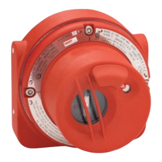
Models FL3100H/3101H 10.7 Final Assembly Figure 24: P/N 71450 FL3100H (UV/IR), Final Assembly... -
Page 71: Figure 25: P/N 71451 Fl3101H (Uv), Final Assembly
Models FL3100H/3101H Figure 25: P/N 71451 FL3101H (UV), Final Assembly... - Page 72 ADDENDUM Product Disposal Considerations This product may contain hazardous and/or toxic substances. EU Member states shall dispose according to WEEE regulations. For further General Monitors’ product WEEE disposal information please visit: www.generalmonitors.com/customer_support/faq_general.html All other countries or states: please dispose of in accordance with existing federal, state and local...
Need help?
Do you have a question about the L3100H and is the answer not in the manual?
Questions and answers