Table of Contents
Advertisement
Advertisement
Table of Contents

Related Manuals for Jands HUB 24

Summary of Contents for Jands HUB 24
- Page 2 It is recommended that all service and repairs on this product be carried out by JANDS ELECTRONICS Pty Ltd or its authorised service agents.
-
Page 3: Table Of Contents
Contents Table of Contents Introduction ...............1 Equipment Description .............3 Getting Started ..............4 Positioning the Unit ..................4 Connecting power.....................4 Set DMX start channel ..................4 Connecting loads ....................5 Connecting DMX-512 ..................5 Power-up sequence ...................5 Dimmer Operation .............7 Main Screen......................7 Menu structure....................7 4.2.1 DMX Start Channel (1-1) ..............8 4.2.2 DMX Cross Patch (1-2) .................9... - Page 4 Contents 4.2.23 Clear Error Log (5-5)................15 4.2.24 Control Source (5-6)................15 4.2.25 Record a Snapshot (6-1) ..............16 4.2.26 Record a Chase (6-2-#-1) ..............16 4.2.27 Chase Parameters (6-2-#-2)..............16 4.2.28 Clear a Chase (6-2-#-3) ............... 17 4.2.29 Playback a Snapshot (7-1) ..............17 4.2.30 Playback a Chase (7-2) ................
- Page 5 Contents Appendix A Using the Dimmer Utility........31 A.1 Installation ......................31 A.2 Main Window ....................32 A.3 File Download utility..................32 A.4 Curve Editor utility..................33 A.5 Logo Generator utility ..................36 Appendix B PC Download Cable .........40 Revision 1.0 - 7-May-02 HUB24 Series Dimmer Operating Manual...
- Page 6 • Reinforced Protective Cover (part No. JND-DC-HUB24). • HUB Download Kit (part No. JND-HUB24DOWNLOAD) - PC Download cable - Jands Dimmer Utility software • Wall mounting bracket (part No. JND-HUB24WMB). • Hand-Rail Mounting brackets (part No. JND-HUB24HRB). Operating Manual HUB24 Series Dimmer...
-
Page 7: Introduction
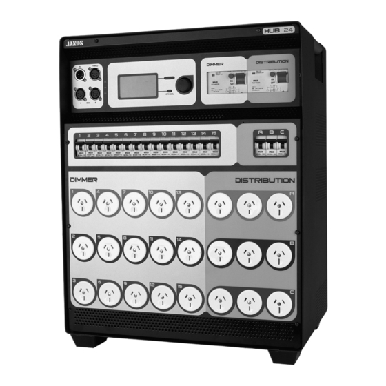
Introduction Introduction The JANDS HUB24 is a unique combination of dimmer channels, power distribution and isolated DMX splitting, all in one compact and low noise package. The HUB24 is specifically designed for demanding touring and theatre applications and is ideal for shows where a mixture of conventional and automated lights are used. - Page 8 Equipment Description Figure 2.1 Operating Manual HUB24 Series Dimmer...
-
Page 9: Equipment Description
Equipment Description Equipment Description Front panel layout Figure 2.1 Phase Power LEDs: Three different coloured LEDs (one for each phase) indicate that the mains supply phases are available. Red for phase A, White for phase B and Blue for phase C. Display: Large graphics LCD, used to display dimmer status information and to control the menus. -
Page 10: Getting Started
100mm behind, 200mm above and 100mm on each side. The unit’s feet provide air intakes (front, back & 2 sides), these openings must not be obstructed. See section 6.2 for wall mounting details. See your Jands distributor for other mounting options. Connecting power The three phase cable must be completely removed from the cable tray before applying power to the unit. -
Page 11: Connecting Loads
Getting Started Connecting loads Power down the HUB24. Plug in the loads to the Dimmer output sockets. It is recommended that, where practical, the load on the dimmer outputs be evenly spread across the 15 channels. This will minimise fan noise and make it harder to overload a single phase. Ensure the load on each dimmer output is greater than the minimum (see section 5.7). - Page 12 Dimmer Operation Menu Structure Overview MENU 1 DMX Settings 1-1 Start Channel 1-2 Cross Patch (for each output) 1-3 DMX Terminate 1-4 Loss of Signal 2 Dimmer Output 2-1 Control Curve (for each output) 2-2 Current Limit 3 Test 3-1 Drive Output (for individual, phase or all outputs) 3-2 Build Output (for individual, phase or all outputs) 3-3 Clear Test 4 System Settings...
-
Page 13: Dimmer Operation
Dimmer Operation Dimmer Operation This section assumes the dimmer has been correctly connected to three phase power and a source of DMX input signal, as described in section 3. In this manual, references to individual front panel buttons will be in uppercase bold text, eg. -
Page 14: Dmx Start Channel (1-1)
Dimmer Operation Select Ch 1 - Next A l l Phase A Phase B A typical menu screen Information displayed on a menu: 1. Numbering showing the current location within the menu tree. 2. Tabs showing the number of items in this sub-menu with current position highlighted. -
Page 15: Dmx Cross Patch (1-2)
Dimmer Operation 4.2.2 DMX Cross Patch (1-2) Menu 1 DMX Settings 1-2 Cross Patch Each of the HUB24’s dimmer outputs can be set to individually respond to any DMX channel, from 1 to 512. This allows the outputs to be patched out of sequence. •... -
Page 16: Supply Current Limit (2-2)
(eg. fluorescent tubes) or if any special curve is required. The user definable curves are created and edited on a PC (or Laptop) using Jands Dimmer Utility software and downloaded to the dimmer. See appendix A for how to use the Dimmer Utility software and see section 4.4 on how to download the curves... -
Page 17: Build Outputs (3-2)
Dimmer Operation Single Phase or All Outputs • Select “3-1 Drive Output” on the menu. • Turn the encoder wheel to highlight either “All”, “Phase A”, “Phase B” or “Phase C” and press SELECT. • All the selected outputs will be set to zero. Turn the encoder wheel to directly change the drive level of all the selected outputs. -
Page 18: Display Contrast (4-1-3)
Dimmer Operation 4.2.12 Display Contrast (4-1-3) Menu 4 System Settings 4-1 Display 4-1-3 Contrast The contrast of the LCD display can be changed to suit the required viewing angle. • Select “4-1-3 Contrast” on the menu. • Turn the encoder wheel to change the contrast level (1 is light, 16 is dark). •... -
Page 19: Set Time & Date (4-4)
Dimmer Operation − LCD Contrast and Backlight to defaults. − Main Screen to Normal. − Playback Mode to Override. − Chase parameters to defaults (chase steps are not affected). Other Settings such as DMX cross patch and the time are not changed. To ensure all dimmer outputs are restored to DMX control, select “3-3 Clear Test”... -
Page 20: Software Version (5-1)
Select “5-1 Software Version” on the menu to display the version and date of the operating software currently in the HUB24. This changes when a new version of the operating software is downloaded into the unit. Refer to the Jands web site for the latest version: www.jands.com.au... -
Page 21: Error Log (5-4)
Dimmer Operation 4.2.22 Error Log (5-4) Menu 5 Diagnostics 5-4 Error Log When an event occurs that generates an error or warning, a message is immediately displayed on the LCD and an entry is placed in the error log. Neutral Earth Warnings – see section 5.1.4. Fan Activated Warning –... -
Page 22: Record A Snapshot (6-1)
Dimmer Operation 4.2.25 Record a Snapshot (6-1) Menu 6 Record 6-1 Snapshot The HUB24 can record up to 8 snapshots, which can be played back later. A snapshot is a grab of the drive level of all 15 dimmer outputs. •... -
Page 23: Clear A Chase (6-2-#-3)
Dimmer Operation • Select “6-2 Chase” on the menu. • Turn the encoder wheel to highlight the desired chase and press SELECT. • Turn the encoder wheel to highlight “Parameters” and press SELECT. • Turn the encoder wheel to highlight either “Level” or “Speed” or “Crossfade”... -
Page 24: Playback A Chase (7-2)
Dimmer Operation 4.2.30 Playback a Chase (7-2) Menu 7 Playback 7-2 Chase When playing back a chase, it can be assigned control of all dimmer outputs or a selection of dimmer outputs. Channels in the chase that have not been assigned an output will be ignored. -
Page 25: Download From Pc
2. Connect the PC Download cable between the computer serial/COM port and the DMX input of the dimmer. Disconnect any DMX terminators. 3. Start the “Jands Dimmer Utility” software on the PC and prepare to download. 4. Press and hold the CANCEL button while turning on power to the HUB24. -
Page 26: Fault Diagnosis
Fault Diagnostics Fault Diagnosis NOTE Contact your authorised JANDS Distributor for repairs or servicing. In Australia refer all repairs to an authorised JANDS service agent or return the faulty unit in suitable packaging to: JANDS Electronics Pty Ltd Service Department... -
Page 27: Thermal Protection
If a message appears on the display like “ADR ERROR EXCEPTION XXXXXXXX XXXXXXXX” where the Xs represent different characters, write down the complete message and contact JANDS Service Department or your local JANDS Distributor, giving details of the dimmer’s operating conditions that caused the error. Press either button to restart the dimmer, if the error prevents normal operation a Deep Clear will be required (see section 4.3). -
Page 28: Dmx Faults
Fault Diagnostics DMX faults Loss of DMX signal will be indicated by “ – NO DMX – ” displayed at the bottom of the main screen. When DMX signal is lost, the dimmer will respond as configured until a new DMX signal is provided, or a Snapshot or Chase function is selected. See section 4.2.4 for configuring “Loss of DMX Signal”. -
Page 29: Fault Finding Guide
Fault Diagnostics Fault finding guide FAULT SYMPTOM POSSIBLE CAUSE REMEDY One or more channels don’t respond Playback or Build are active See sections 4.2.9 and 4.2.31 to DMX control. DMX start channel is set incorrectly Change DMX start channel DMX cross patch is set incorrectly Change DMX cross patch Not receiving DMX signal Check console and cabling,... - Page 30 Fault Diagnostics FAULT SYMPTOM POSSIBLE CAUSE REMEDY One or more channels won’t Current limit reached Reduce the load on that phase drive to full Adjust current limit setting to a higher value (see 4.2.6) Recalibrate current (see 4.2.21) Fan Activation warning Unbalanced load Spread the loads out more evenly across the dimmer outputs.
-
Page 31: Installation
Installation Installation Free Standing The HUB24 is primarily convection cooled, with the main air intake at the bottom and air exhaust at the back and sides - these openings must not be obstructed. Correct positioning and adequate ventilation are essential. The HUB24 must be in the upright position, standing on its feet. -
Page 32: Maintenance
If the heatsinks are clogged with dirt or fluff, the dimmer must be disassembled by an authorised Jands service agent and the heatsinks cleaned. Do not attempt to clean the heatsinks by blowing compressed air through the vent holes in the chassis. -
Page 33: Technical Data And Specifications
Technical Data and Specifications Technical Data and Specifications PARAMETER HUB24 No. of Outputs - Dimmer: Distribution: Opto DMX Out: Input Power 3 Phases plus Neutral and Earth Requirements: 200-265 volts phase-to-neutral 345-460 Volts AC Phase-Phase +/-10% Full size Neutral conductor 50 Amps / Phase Upstream protection: Max 50A per phase... -
Page 34: Dmx Connector Pin-Outs
Technical Data and Specifications PARAMETER HUB24 Mains measurements – Voltage accuracy: Current accuracy: Power Supply Entry: 3 metre tail with Clipsal 56P532 plug Output Connectors – Dimmer: 15 x 10 amp Clipsal 10MP Distribution: 6 x 10 amp Clipsal 10MP 3 x 15 amp Clipsal 10MDP15 Size (mm):... -
Page 35: Mains Power - Block Diagram
Technical Data and Specifications 8.2.1 Mains Power - Block Diagram Current Monitor Phase A Mains Phase B Supply Phase C Phase LEDs ISO 1 ISO 2 Control Dimmer Distribution Electronics Circuit Breakers Dimmer Circuits Output Sockets Figure 8.1 8.2.2 Mains wiring colour codes PHASE A PHASE B WHITE... -
Page 36: Normal Three Phase Plus Neutral Operation
Technical Data and Specifications 8.2.3 Normal Three Phase plus Neutral Operation The HUB24 is normally supplied with a three phase power cable and plug attached, suiting the vast majority of available mains supplies (ie. three phase and neutral). The incoming mains supply must be protected by upstream circuit breakers or fuses rated at not more than the ‘Upstream protection’... -
Page 37: Appendix A Using The Dimmer Utility
These instructions assume the user has basic experience with Microsoft Windows. For help in this area consult the Windows manual or click Help on the Start menu. Installation The Jands Dimmer Utility software must be installed on an IBM compatible laptop or desktop computer. System Requirements •... -
Page 38: Main Window
Main Window On the Windows Start menu, click Programs Jands Dim_Utility, to start the Jands Dimmer Utility. The main window will appear across the top of the screen. Its main purpose is to launch the three utilities: • File Download •... -
Page 39: Curve Editor Utility
Using the Dimmer Utility 3. If a Curve file has been selected, the window will change to allow entering curve number and name. Click either Curve #1 or Curve #2 and type in a curve name if it needs to be changed. 4. - Page 40 Using the Dimmer Utility Graphically Editing a Curve The curve editor provides four graphical editing methods and for very fine changes there is a fine adjustment section. These graphical editing methods are: • Line • Curve • Freehand • While editing, the position of the mouse pointer within the graph, is shown in the bottom left hand corner.
- Page 41 Using the Dimmer Utility Blank Blank sets the power output to zero for every control input value, this is used to start drawing a new dimming curve. On the Edit menu click Blank (or click the blank icon) to zero the curve in the editor. Linear Linear sets the power output directly proportional to the control input value, this is used to start drawing a new dimming curve.
-
Page 42: Logo Generator Utility
Using the Dimmer Utility Logo Generator utility The logo generator is used to draw customs logos from scratch, to modify existing images and to download logos to the dimmers. This is achieved using the following main functions: • Opening an existing logo file •... - Page 43 Using the Dimmer Utility Graphically Editing a Logo The logo generator provides four graphical editing methods and erase functions. The graphical editing methods are: • • Line • Marquee • Text While editing, the position of the mouse pointer within the grid, is shown in the bottom left hand corner.
- Page 44 Using the Dimmer Utility Redo On the Edit menu click Redo (or click the redo icon) to reverse the action of the last undo. Each click reverses one more undo. Blank Blanks the entire logo (sets all pixels to white), this is used to start drawing a new logo. On the Edit menu click Blank (or click the blank icon) to blank the logo.
- Page 45 Using the Dimmer Utility Erasing the Logo from a Dimmer The logo and password that are currently in the dimmer can be erased. 1. On the File menu click Erase Logo (or click the lightning icon) to open the erase logo window.
-
Page 46: Appendix B Pc Download Cable
Circuit – PC Download Cable Appendix B PC Download Cable The following cable can be used for downloading files from a PC to both HP dimmers and HUB24 dimmers. It consists of very commonly available parts. Parts List 1x Female D9 connector 1x D9 backshell 2x 1K ¼watt resistors 2x 1N914 diodes...
Need help?
Do you have a question about the HUB 24 and is the answer not in the manual?
Questions and answers