Table of Contents
Advertisement
Quick Links
Advertisement
Table of Contents
Troubleshooting

Summary of Contents for Accu AXIOM
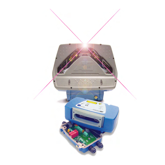
- Page 1 ™ ™ AXIOM / AXIOM-X Laser Bar Code Scanning Solutions Product Line Manual...
- Page 2 Sort Systems, Inc. All drawings and specifications contained in this manual are the property of Accu-Sort Systems, Inc. and shall not be reproduced, copied or used in whole or in part as the basis for the sale or manufacture of products without the written permission.
-
Page 3: Table Of Contents
Preparing to Install ..................... 17 Installation Sequence(s)..................... 18 Orientation Considerations..................19 Read Range....................... 19 Bar Code Orientation to Scanning Area (AXIOM) ............. 20 Bar Code Orientation to Scanning Area (AXIOM-X) ..........21 General Mounting Guidelines..................22 Reader Positioning..................... 22 Dimensions and Clearances ..................23 Attaching the Wiring Base.................. - Page 4 To open a communications port................72 Reader's Information Buttons ................72 To connect to an AXIOM via a network..............73 To Add an AXIOM to the Reader's IP Address list ..........74 Modify ........................75 AXIOM Configuration ....................76 Reader Information ....................76 Configuration Options ..................
- Page 5 9 Service Replacement Procedures..................159 External Devices ...................... 159 Field Replaceable Units (FRUs)................159 AXIOM / AXIOM-X Illustrated Recommended Spare Parts List ......160 Replacing a Scan Head ................... 162 Replacing a Wiring Base..................163 Replacing an I/O Module..................164 Replacing a Power Supply ..................
- Page 6 EtherNet/IP ......................190 Remote Setup and Diagnostics ................196 EtherNet/IP Object Models ..................198 D FAST Monitor How to Configure an AXIOM for FAST Monitor Compatibility ........205 E Installation Drawings Mechanical Drawings / Interconnection Drawings List ........... 209 Index Accu-Sort Systems, Inc.
-
Page 7: Intended Audience
Thank You Thank you for using an AXIOM bar code scanning solution and this manual. We value your comments and feedback. Feel free to let us know what you like or dislike about the product (or this manual) by e-mailing us at info@accusort.com. -
Page 8: Conventions
Customer Service Training Accu-Sort Systems offers a complete set of training courses to help you and your staff get the most out of your investment. We can help you develop a training plan that provides thorough training for both your project team and your end users. -
Page 9: Introduction
AXCESS User Interface AXIOM Product Line Overview The AXIOM line of laser bar code readers is designed with industrial and manufacturing applications in mind. The AXIOM line scanners offer high- speed scanning and high reliability in a rugged industrial enclosure. An omnidirectional reader, the AXIOM-X, is also available. -
Page 10: Axcess™ Configuration Setup Software
Modify the AXIOM output messages to accommodate your system needs. Add or modify the bar code symbologies to be read by AXIOM. Define up to four (4) relay input/outputs. Monitor AXIOM performance using various diagnostic tools. You can easily configure your AXIOM reader by using the AXCESS Setup Software, a desktop or laptop computer, and the setup programming cable. -
Page 11: Safety
Please follow the safety precautions and warnings found in this manual when installing, setting up, operating, maintaining, troubleshooting or replacing any Accu-Sort products, parts, or related equipment. Following these precautions will prevent personal injury or damage to the unit. Failure to follow these precautions may also void your warranty. -
Page 12: General Precautions
General Precautions Installation and Service by Qualified Service Technician Only WARNING: All procedures involving exposure to the inside of the AXIOM readers must be performed by a trained technician because of possible exposure to high voltage. There are no user-serviceable parts inside. Do... -
Page 13: Compliance Requirements
Safety Compliance Requirements FCC NOTICE: The AXIOM product line has been tested and found to comply with the limits for a Class A digital device, pursuant to Title 47, Part 15 of the FCC Rules. These limits are designed to provide a reasonable protection against harmful interference when the equipment is operated in a commercial environment. -
Page 14: Electrical Grounding Requirements
AXIOM / AXIOM-X Product Line Manual ™ ™ Safety Electrical Grounding Requirements Before applying power to any device, ALL components MUST be electrically grounded. Follow these precautions: Ensure all AC power outlets have a properly grounded receptacle. ALL components MUST be properly cabled and grounded with three- conductor AC power cords. -
Page 15: Laser Safety
Safety Laser Safety The AXIOM uses visible laser diodes and emits a “moving” red beam. Do not stare into the AXIOM’s exit window at the laser light source. Avoid unintentional exposure to laser light whenever possible. The laser light level does not constitute a health hazard, however staring at the laser light for prolonged periods could result in eye damage. -
Page 16: Safety Labels And Locations
Safety Labels and Locations Refer to the following figures for specific label locations and warnings. When operating, repairing, or replacing an AXIOM / AXIOM-X, note all label content on the unit. These labels provide special precautions for operation, usage specifications, product identification, and service information. -
Page 17: Mechanical Installation
™ Mechanical Installation 3 Mechanical Installation This chapter defines a typical AXIOM / AXIOM-X installation and highlights important details that may affect how the reader should be mounted, wired, and configured for optimum performance in your application. Be sure to consider the various factors that affect how the reader must be mounted with respect to the scanning area. -
Page 18: Installation Sequence(S)
Erect mounting frame or other supporting structures. Attach the Universal Mounting Bracket (UMB) to the frame. (UMB and mounting frame options are available from Accu-Sort.) Mount the wiring base to the UMB or frame. Mount the Accu-Sort power supply to the UMB (optional). -
Page 19: Orientation Considerations
(yaw, pitch and roll angles) Read Range The AXIOM / AXIOM-X must be positioned in the scanning area to accommodate reading products over a read range specific to your application. Use the following diagram to determine the near and far read distances. -
Page 20: Bar Code Orientation To Scanning Area (Axiom)
Mechanical Installation Bar Code Orientation to Scanning Area (AXIOM) Picket Fence or Ladder Orientation Bar code placement usually determines the AXIOM’s positioning. The AXIOM can be mounted to read codes in either a ladder or picket fence orientation. Picket Fence Orientation Ladder Orientation Bar Code Skew, Pitch and Tilt These angles affect bar code readability. -
Page 21: Bar Code Orientation To Scanning Area (Axiom-X)
AXIOM-X Orientation with Reference to Conveyor Travel IMPORTANT: There are several parameters associated with the mounting of the AXIOM-X that must be configured to the application. For details, reference Chapter 5. See Modify > Tracking – AXIOM Mounting. 03-AXIOM-AXIOM-X_Mechanical_Installation_R10.doc... -
Page 22: General Mounting Guidelines
See Chapter 2, Safety. Reader Positioning IMPORTANT: The AXIOM readers are able to decode bar codes at a variety of angles; however significant angular distortion may degrade reading performance. When positioning a reader, be aware of how the scanning beam exits the scan window in relation to the wiring base. -
Page 23: Dimensions And Clearances
™ Mechanical Installation Dimensions and Clearances The overall dimensions of the AXIOM / AXIOM-X when the Universal Mounting Bracket (UMB) is used are shown on the mechanical specification drawings provided in Appendix E. The reader is a sealed, unventilated unit. No specific clearance is required for the purpose of cooling. -
Page 24: Attaching The Universal Mounting Bracket (Umb)
Attaching the Universal Mounting Bracket (UMB) The Universal Mounting Bracket (UMB) simplifies reader mounting and installation. The AXIOM / AXIOM-X both use the same wiring base and UMB. They must be assembled and attached to the mounting structure before beginning wiring procedures. -
Page 25: Attaching The Power Supply To Umb
AXIOM / AXIOM-X Product Line Manual ™ ™ Mechanical Installation Attaching the Power Supply to UMB The power supply accessory is used when an alternative DC power source is not available. Power supplies are available in IP40 and IP65 ratings for both domestic and international applications. - Page 26 AXIOM / AXIOM-X Product Line Manual ™ ™ Mechanical Installation Installing the IP65-rated power supply: 1. Mount the power supply (1) to the power supply mounting plate (2) with the provided hardware (3). 2. DO NOT over-tighten screws that hold the power supply to the adapter mounting plate.
-
Page 27: Attaching The X-Pattern Mounting Bracket (Xmb, Axiom)
IMPORTANT: The correct read distance reference plane is from the mounting edge of the XMB and not the AXIOM exit window. Correct Read Distance Reference Plane (0”) - Page 28 AXIOM / AXIOM-X Product Line Manual ™ ™ Mechanical Installation Mount wiring bases to XMB: 1. Attach XMB (1) to mounting structure with the provided hardware (2). 2. Mount both wiring bases (3) to the XMB. Use the three screws (4) provided with each wiring base.
- Page 29 AXIOM / AXIOM-X Product Line Manual ™ ™ Mechanical Installation Mount Power Supply to XMB: 1. Mount the power supply (1) to the power supply adapter mounting plate (4) (included with the XMB kit). The XMB kit provides the necessary hardware (2).
-
Page 30: Mounting The Trigger Photoeye
The reflector must be mounted perpendicular to the conveyor, facing the photoeye. When mounting the photoeye to an Accu-Sort structure, see drawing 41222 in Appendix E. IMPORTANT: The trigger photoeye’s beam (between photoeye and reflector) must be blocked by a package before the bar code is in position for scanning. -
Page 31: Mounting The Height Tracking Photoeyes
AXIOM / AXIOM-X Product Line Manual ™ ™ Mechanical Installation Mounting the Height Tracking Photoeyes Height Tracking Photoeyes are required when package spacing (i.e., distance between packages traveling through the scanning area) is under 1/3 of the total depth of field (DOF). Each additional photoeye cuts the package spacing requirement in half, down to a minimum of 2 inches [50.8... - Page 32 Mechanical Installation Three photoeyes allows spacing of 2 inches [50.8 mm] which is the minimum allowable package spacing. IMPORTANT: Contact Accu-Sort’s Application Engineers for applications requiring package spacing less than two inches [50.8 mm]. Height Tracking Photoeyes (Front View) NOTE: The Height Tracking Photoeye kit includes a DC Input Module that must be installed in the wiring base.
-
Page 33: Mounting The Tachometer
The general mounting kit makes tachometer mounting and setup easier. The extrusion mounting kit (same as shown here) also includes mounting hardware for attaching to Accu-Sort mounting structures. If you are not using the tachometer mounting kit, create a weight or spring assembly to put tension on the back of the tachometer, ensuring that the wheel makes strong contact with the conveyor. -
Page 34: Mounting The I/O Modules
AXIOM / AXIOM-X Product Line Manual ™ ™ Mechanical Installation Mounting the I/O Modules The wiring base supports four (4) optional input or output modules that can be used for trigger inputs or to operate diverters, alarms, etc. The optional I/O modules are not installed at the factory. - Page 35 AXIOM / AXIOM-X Product Line Manual ™ ™ Mechanical Installation To install the optional I/O module(s): 1. Lift the insulating cover to gain access to the wiring base. 2. The I/O modules may be plugged into locations I/O 1 through I/O 4.
-
Page 36: Check Scan Head Excessive Shock Indicator
Mechanical Installation Check Scan Head Excessive Shock Indicator IMPORTANT: AXIOM / AXIOM-X scan heads may have been equipped with an excessive shock indicator. The purpose of this indicator is to assure that scan heads that have experienced shock in excess of 75G are not installed at product scan points. -
Page 37: Installing An Axiom Scan Head
™ ™ Mechanical Installation Installing an AXIOM Scan Head Perform the electrical installation as outlined in Chapter 4. Once all wiring is checked for accuracy, install the scan head to the wiring base. The scan head can be installed with or without the power disconnected from the wiring base. - Page 38 AXIOM / AXIOM-X Product Line Manual ™ ™ Mechanical Installation Wiring Base Connector Alignment Scan Head Connector 3. Gently press the scan head down until it firmly connects with the wiring base. 4. Secure the scan head to the wiring base with the four captive screws.
-
Page 39: Installing An Axiom-X Scan Head
Installing an AXIOM-X Scan Head Perform the electrical installation as outlined in Chapter 4. Once all wiring is checked for accuracy, install the AXIOM-X scan head to the wiring base. You can install the scan head with or without the power disconnected from the wiring base. - Page 40 AXIOM / AXIOM-X Product Line Manual ™ ™ Mechanical Installation Wiring Base Connector Alignment Scan Head Connector 4. Gently press the scan head down until it firmly connects with the wiring base. 5. Secure the scan head to the wiring base with the four captive screws.
-
Page 41: Safety During Axiom-X Scan Head Installation
™ ™ Mechanical Installation Safety during AXIOM-X Scan Head Installation CAUTION: Although the scan head only weighs 14.5 lbs [6.6 kg] proper lifting techniques are still required to avoid the potential for back injuries. Top Read Installation with Overhead Space 1. - Page 42 AXIOM / AXIOM-X Product Line Manual ™ ™ Mechanical Installation Side Read Installation 1. Install scan head onto wiring base with the mounting bracket adjusted as shown. 2. Use upper body or torso to stabilize scan head as you tighten the four screws that hold it to the wiring base.
-
Page 43: Electrical Installation
IMPORTANT: The AXIOM / AXIOM-X contain electronics that may be affected by electrostatic discharge (ESD). To prevent personal injury or damage to the unit, please follow the safety precautions and warnings found in Chapter 2. -
Page 44: Installation Sequence(S)
NOTE: To reduce the possibility of damage to the scan head, install it after the wiring base is mounted, wired, and all wiring is checked for accuracy. Be sure to perform the polarity check before attaching the scan head. Setup your AXIOM / AXIOM-X. See Chapter 5. Check operations. -
Page 45: General Electrical Installation Guidelines
(binoculars or telescopes). Avoid unintentional exposure to laser light whenever possible. As you plan and install your AXIOM bar code solution application, be sure to keep the following guidelines in mind: Determine the reader is in the proper orientation and position as outlined in Chapter 3. -
Page 46: Wiring The Axiom / Axiom-X
Wiring the AXIOM / AXIOM-X After completing mechanical installation, use this section to properly wire you AXIOM reader for optimal performance in your application. All wiring connections are made via the wiring base. Use the four conduit openings for running wires into the base. Route your cabling for input/output power, tachometer, trigger, communications, and I/O, through the recommended conduit openings. - Page 47 AXIOM / AXIOM-X Product Line Manual ™ ™ Electrical Installation WARNING: To assure no ESD damage will occur, be sure to observe the precautions outlined in Chapter 2, Safety. IMPORTANT: Ground the wiring base to safety ground (protective earth ground (PE)). See wiring recommendations for safety ground.
-
Page 48: Cable And Conduit Connections
“T” connector to assure the reader will be watertight. Make sure you use Teflon tape (or other thread sealant) to maintain the reader’s IP rating. (AXIOM is IP65, AXIOM-X is IP54.) Once all cabling is completed, plug all unused wiring base openings. - Page 49 AXIOM / AXIOM-X Product Line Manual ™ ™ Electrical Installation Conduit Connections to Wiring Base Where the conduit meets with the wiring base, you will need to supply the correct conduit fittings. Use flexible conduit whenever possible to allow for range of motion adjustments, especially when the UMB is used.
-
Page 50: How To Maintain An Ip65 Rating
™ Electrical Installation How to Maintain an IP65 Rating IMPORTANT: Use the Teflon tape provided with the AXIOM / AXIOM-X wiring base to assure the unit maintains its IP65 rating. 1. Wrap the cord grips with Teflon tape. 2. Install the cord grips into the wiring base openings. -
Page 51: Power Supply Connections
The outlet must be a readily accessible disconnect device. Using Accu-Sort Power Supplies Single Reader The AXIOM readers require 30 watts (maximum) of power. Accu-Sort power supply options are available for either domestic or international installations and are rated for IP40 and IP65 environments. - Page 52 LPS or Class 2 power supply. The supply must provide 30 watts (12-30 VDC) of power to each reader. Single Reader When a single reader application uses a non Accu-Sort supply, follow the INPUT POWER wiring table to assure proper wiring.
-
Page 53: Polarity Check
Location of Polarity LED in Wiring Base 1. Apply power. 2. Check that all Polarity LEDs are GREEN. If multiple AXIOM-X are daisy- chained together, check the polarity of the first unit in the chain (i.e., unit wired directly to power source), then the second, then the third. If all Polarity LEDs are GREEN, polarity is correct. -
Page 54: Trigger Connections
Common BLACK If your application uses a photoeye other than the one available from Accu- Sort, follow the TRIGGER wiring table to assure proper wiring. The trigger must be able to operate using the +24VDC source (24V) and not draw more than 100mA. -
Page 55: Tachometer Connections
The shielding for the tachometer wiring MUST be terminated to earth ground. Otherwise, belt static could result in a system failure. Tachometer Shielding Terminated to Earth Ground If your application uses a tachometer other than the one available from Accu- Sort, follow the TACH wiring table to assure proper wiring. 04-AXIOM-AXIOM-X_Electrical_Installation_R10.doc... - Page 56 Electrical Installation Multiple Readers When an application incorporates multiple readers wire the tachometer to the AXIOM / AXIOM-X Controller. (See drawings 107480 and 107481 in Appendix E.) Using Ferrite Clamps when Wiring Tachometer In order to absorb transient currents generated by motors and belts, two ferrite clamps should be added to the TACH cable as shown below.
-
Page 57: Rs232/422 Communications Connections
SERIAL COM / RS232 wiring table to assure proper wiring. IMPORTANT: Before attempting to use RS232 communications with RTS/CTS, contact Accu-Sort Customer Service for additional information. RS422 Connections Use RS422 for a direct connection to a controller, personal computer, or other device. -
Page 58: Ethernet Communications Connections
IMPORTANT: Do not strip wires before inserting them into the Ethernet terminal block. For additional details on Ethernet and EtherNet/IP communications, go to Appendix C: AXIOM Networking Guide. Another useful source of information is the ODVA official web site (www.odva.org). NOTE: To simplify your network installation, Accu-Sort offers the following... -
Page 59: I/O Module Connections
* Derate 33mA/deg above 25C. Proper I/O module wiring is shown for the following applications on drawings found in Appendix E: 107482 – End Trigger Photoeye 109364 – Height Tracking Photoeyes (for AXIOM-X) 107483 – Stack Light 04-AXIOM-AXIOM-X_Electrical_Installation_R10.doc Accu-Sort Systems, Inc. - Page 60 (See drawing 107482 in Appendix E.) It can also be used for Height Tracking Photoeyes. (See drawing 109364 in Appendix E.) NOTE: Any other input module application requires custom software. Contact Accu-Sort Customer Service for more information. Accu-Sort Systems, Inc. 04-AXIOM-AXIOM-X_Electrical_Installation_R10.doc...
-
Page 61: Installing A Scan Head
Installing a Scan Head Once all wiring is completed and checked for accuracy, install the AXIOM or AXIOM-X scan head to the wiring base. (See Chapter 3.) You can install the scan head with or without the power disconnected from the wiring base. - Page 62 AXIOM / AXIOM-X Product Line Manual ™ ™ Electrical Installation Notes: Accu-Sort Systems, Inc. 04-AXIOM-AXIOM-X_Electrical_Installation_R10.doc...
-
Page 63: Setup
Setup 5 Setup Getting Started The AXIOM bar code readers are designed for ease-of-setup so they can be seamlessly configured for your application. AXCESS Setup Software for AXIOM is the tool you will use to define operating parameters, determine bar code read quality, and construct output messages, including filtering, stripping and padding capabilities. -
Page 64: To Install The Axcess For Axiom Software
4. Double-click the Setup.exe icon. 5. Follow the AXCESS Setup Wizard prompts to install the AXCESS Setup Software on your computer. 6. After the “AXIOM AXCESS setup was completed successfully” message is displayed, click “OK”. To start the AXCESS for AXIOM software: 1. -
Page 65: Axcess User Interface Basics
AXIOM / AXIOM-X Product Line Manual ™ ™ Setup AXCESS User Interface Basics This chapter introduces you to the AXCESS user interface and teaches you a few simple concepts and functions you need to start working with AXCESS. Specifically, this chapter describes how to: Use AXCESS Wizard’s step-by-step approach to configuring a reader. - Page 66 AXIOM / AXIOM-X Product Line Manual ™ ™ Setup Drop-down List Option Group Button Drop-down Menus Toolbar AXCESS Explorer Modal Window Region Status Line AXCESS Wizard AXCESS User Interface Accu-Sort Systems, Inc. 05-AXIOM-AXIOM-X_Setup_R10.doc...
- Page 67 AXCESS Wizard Use AXCESS Wizard’s 3 buttons (previous, next, and reset) to logically step through the process of completely configuring an AXIOM reader. Recommended for first-time/novice users. AXCESS Explorer Use AXCESS Explorer’s navigation list when you need to modify specific setup parameters, save/retrieve settings, or access reader diagnostics.
-
Page 68: Navigating Axcess
AXIOM / AXIOM-X Product Line Manual ™ ™ Setup Navigating AXCESS Once you proceed to the next screen and begin reader setup, the Main window is not accessible again until you exit and restart AXCESS. Click the Next button to continue to the Modify window. - Page 69 AXIOM / AXIOM-X Product Line Manual ™ ™ Setup AXCESS Explorer The functions that you can select are displayed in a navigation list on the left–hand side of the AXCESS Explorer frame. The function list is organized much like the hierarchy of a file system, where you can expand items that begin with a plus sign (+) to further sub–levels until you find a function of...
-
Page 70: Getting Help
AXIOM / AXIOM-X Product Line Manual ™ ™ Setup Getting Help AXCESS provides complete online help. Whenever you need assistance, simply choose an item from the Help Index to pinpoint the information you want. To display help for a current window: 1. -
Page 71: Connecting To An Axiom
To connect to an AXIOM via the setup cable: 1. Connect the programming cable to the setup connector located on the front of the wiring base. (All AXIOM readers use the same type of wiring base and programming cable.) 2. Connect the other end of the programming cable to your computer. Be sure to note which COM port you are connected to on your computer. -
Page 72: To Open A Communications Port
2. Once the reader connection is complete, the message “Connected by serial cable” appears in the status line. 3. The Connection window displays the Reader’s Information. The type of AXIOM (1L, 2L, 4L) or AXIOM-X (2L, 4L) is identified in the Reader model line. Connection – Open Port 4. -
Page 73: To Connect To An Axiom Via A Network
3. In the Connection Mode options group, click Network. 4. Select the IP address of your AXIOM from the Reader’s IP Address list. (If this is your first time, you may need to add the AXIOM’s IP address to the Reader’s IP Address list.) 5. -
Page 74: To Add An Axiom To The Reader's Ip Address List
Product Line Manual ™ ™ Setup To add an AXIOM to the Reader’s IP Address list 1. Click the Add IP button. The Add/Edit IP Address popup window appears. 2. Enter the IP address and reader name in the fields. -
Page 75: Modify
™ Setup Modify After establishing a connection with your AXIOM reader, use the Modify menu to set all operational parameters to fit your application. NOTE: AXCESS functionality varies based on the type of AXIOM reader you are setting up. Functions that do not apply to your reader will either not appear on the active screen or will appear grey (rather than black) indicating the function is not applicable. -
Page 76: Axiom Configuration
™ ™ Setup AXIOM Configuration Use the Modify > AXIOM Configuration window to define the reader name and identify the related software names, revisions, and configuration options. Reader Information The Reader Information region of the AXIOM Configuration screen identifies the reader name and current software revisions being used by the AXIOM scan head. -
Page 77: Configuration Options
Control Panel Options The AXIOM’s control panel is very useful during setup. When the Enable AXIOM Control Panel Buttons checkbox is selected, you will be able to use the AXIOM reader’s control panel. (See Chapter 6.) Once setup is complete, disable the control panel buttons to reduce the potential for accidentally changing parameters at the scanning area. -
Page 78: Network Access Options
Modify > AXIOM Configuration > Network Access Options Selection Definition Password for FTP When selected, FTP access to an AXIOM reader is enabled Only when the correct password is entered. Use FTP to update and extract the AXIOM firmware and parameter settings. -
Page 79: Bar Code Setup
The Active Bar Code List identifies all bar code types (maximum 10) and their associated parameters (e.g.: Code #, Code Type, Characters, Mod Check, Quantity) that the AXIOM reader has been setup to search for and decode. The code quantity is specified by a minimum and maximum number of codes. -
Page 80: Adding, Editing, Moving And Removing A Bar Code
AXIOM / AXIOM-X Product Line Manual ™ ™ Setup Moving a Bar Code Highlight a symbology (Code#) listed in the bar code fields. To move the selected symbology toward the top (beginning) of the list, click Move Up. Click Move Down to move the selected symbology further back (toward the end) of the list. -
Page 81: Bar Code Groups
AXIOM / AXIOM-X Product Line Manual ™ ™ Setup Bar Code Groups When more than one bar code type is defined in Bar Code Setup, the Bar Code Groups selection becomes available. This enables you to define the valid “groups” of bar codes that are to be transmitted together. -
Page 82: User-Defined Mod Checks
AXIOM / AXIOM-X Product Line Manual ™ ™ Setup User Defined Mod Checks This window becomes available when you specify a user defined mod check for a symbology while in Modify > Bar Code Setup. Field Definition Factors Define weighting factors for determining mod check value. -
Page 83: Bar Code Padding And Stripping
AXIOM / AXIOM-X Product Line Manual ™ ™ Setup Bar Code Padding and Stripping For each code type (defined in Bar Code Setup), padding and/or stripping of the bar code data can be specified using the Modify > Bar Code Padding and Stripping screen. -
Page 84: Match Codes Setup
In addition to identifying and reading a symbology you defined (using the Modify > Bar Code Setup function), this feature enables you to configure an AXIOM to match specific characters within a bar code. All bar codes are compared to the complete list of Match Codes. If a bar code matches ANY of the codes defined in Match Code Setup it is considered a MATCH. -
Page 85: Serial Communications (Port #)
AXIOM / AXIOM-X Product Line Manual ™ ™ Setup Serial Communications Port#1 Use the Modify > Serial Communications Port#1 window to set the serial port connection parameters (e.g., baud rate, data, bits, stop bits, parity, and flow control) and the message format to the "host" computer. -
Page 86: Message Format
/ AXIOM-X Product Line Manual ™ ™ Setup Message Format You have four format selections for messages the AXIOM reader sends to your host computer (or other device) connected to port#1. Selection Definition Custom Message Enables custom messaging implemented via custom... -
Page 87: Network Settings (Net #)
AXIOM / AXIOM-X Product Line Manual ™ ™ Setup Network Settings The Modify > Network Settings window allows you to specify network settings (including the IP address) for the reader. Currently, the reader can only be configured to use a Static IP address. - Page 88 Number of Client Readers - This number in a multi-reader network must be Configuration defined on the AXIOM Controller. Drop-down list selectable for up to five (5) AXIOM readers functioning as “Clients”. Client readers must be set at zero (0).
-
Page 89: Advanced Network Settings
AXIOM / AXIOM-X Product Line Manual ™ ™ Setup Advanced Network Settings The advanced network parameters are only available when Advanced Setup is selected from Configuration drop-down menu. Under normal circumstances, these should never need to change. Selection Definition Controller... -
Page 90: Ethernet Ip Settings
™ Setup EtherNet/IP Settings EtherNet/IP allows the AXIOM to communicate bar code and I/O data to other EtherNet/IP (EIP) enabled devices on your network. The Modify > EtherNet/IP Settings are only available if EtherNet/IP has been enabled from the Network Settings window. Once enabled, EtherNet/IP Explicit and I/O messaging are enabled. - Page 91 Tag. AXIOM Inputs When Enable Trigger Inputs is selected, the AXIOM Trigger settings are ignored and the AXIOM is triggered solely by manipulating the Trigger Bit in the Output Word (contained within the AXIOM Assembly and Output Objects). AXIOM Outputs...
-
Page 92: Message Definitions (User-Defined Messages)
AXIOM / AXIOM-X Product Line Manual ™ ™ Setup Message Definitions (User-defined Messages) Whenever you specify a user-defined message format for either serial port #1 or network settings, Message Definitions become available within the Modify menu. For the serial port, use the Message Definitions – Port #1 window (shown below). -
Page 93: Message Content
Message Content The message drop-down lists define the message options for each bar code. The message content can be defined for transmissions from the AXIOM’s serial port #1 as well as any network connection (via Net#1). These messages are based on various conditions. For each condition, there are options for what message can be sent. -
Page 94: Trigger And Relay Settings
AXIOM / AXIOM-X Product Line Manual ™ ™ Setup Trigger and Relay Settings Use the Modify > Trigger and Relay Settings window to set the type of trigger. It also provides configurations for the optional input/output relay modules. Example: IO Configuration when Height Tracking Photoeyes are used. - Page 95 AXIOM / AXIOM-X Product Line Manual ™ ™ Setup Trigger Source Options Selection Definition Hardware Trigger Active-High vs. This defines whether trigger is active when the input signal Active-Low is high or low. Debounce Duration Defines the minimum time required for detection of a (ms) change in the hardware trigger status.
-
Page 96: I/O Options
(i.e., photoeye no longer blocked). Learn Match Code When this input is active, the AXIOM is placed into Test Mode in order to “learn” a match code. When the line is deactivated, Test Mode is exited. When this option is enabled, the last code read is stored in the first entry of the Match Table. -
Page 97: Tracking
AXIOM / AXIOM-X Product Line Manual ™ ™ Setup Tracking Use the Modify > Tracking window to define the parameters associated with monitoring package travel on the conveyance system. The tracking parameters are only available if tracking is enabled; otherwise they are not shown in this window. -
Page 98: Axiom Mounting
The point at which bar code data is transmitted. Defines the number of inches after the specified edge of the package passes the trigger before data transmission occurs. AXIOM Mounting Settings Selection Definition Closest Read Point Specify, in inches, the nearest distance from the reader (in.) -
Page 99: Tachometer Source
In all instances, the tachometer configuration can be verified by monitoring “belt speed” on the AXIOM Monitor. The belt speed is displayed in ft/min. Specify Transmit Point All tracking systems, require the transmit point for the bar code to be specified. - Page 100 For proper performance, the following information about the reader mounting is required. The nearest and furthest distance (from the front window of the AXIOM) at which a bar code is to be read. The distance from the trigger source (i.e., Photoeye) to the center point of the AXIOM scan line (Trigger Reference Point).
- Page 101 When two AXIOM readers are mounted to create an X-pattern, they have rotation angles of 45 and 135 degrees or -45 and -135 degrees respectively. NOTE: This only applies to the use of two AXIOM line scanners; it does not apply to AXIOM-X omnidirectional scanners.
-
Page 102: Advanced Tracking
AXIOM / AXIOM-X Product Line Manual ™ ™ Setup Advanced Tracking Setup Procedure To assure tracking accuracy, the Tracking > Trigger Reference Point, Closest Read Point and Farthest Read Point parameters must be properly set to match the application. NOTE: This procedure assumes that the basic setup procedure has already been performed. -
Page 103: Drx (Advanced Settings)
™ Setup CAUTION: Modifying the DRX features within AXCESS may adversely affect the operation of your AXIOM reader. Changes to the DRX parameters should not be made unless recommended by an authorized Accu-Sort customer support technician. The Modify > DRX settings are only available if Configuration > Setup >... -
Page 104: Save/Retrieve Settings
Buttons Definition Save to AXIOM Use to save parameters from AXCESS to the scan head. Parameters saved on the AXIOM scan head’s parameters storage module are the set of parameters that will be used during normal operations. Retrieve from AXIOM Retrieves the current parameters from the AXIOM scan head’s parameters storage module to the AXCESS setup... -
Page 105: Save Parameters To Disk
If you have not already done so, be sure to update the wiring base with the file you have saved, using the Backup AXIOM Parameters to Base button. It is recommended that the previous settings and any changes be stored in separate files, in case it becomes necessary to return the reader to a previous configuration. -
Page 106: Save Parameters From Disk
(See Save to Disk for details.) The parameters are stored in files with a *.pam extension. NOTE: It is good practice to store any *.pam files in the AXIOM AXCESS folder of the AXCESS directory so that they can be easily located. -
Page 107: Backup Axiom Parameters To Base
4. Choose No to save changes before exiting. This returns you to the active AXCESS window. 5. Use one of the save parameter functions (i.e., Save to AXIOM or Save to Disk), then exit AXCESS. 05-AXIOM-AXIOM-X_Setup_R10.doc Accu-Sort Systems, Inc. -
Page 108: Drop-Down Menus
AXIOM / AXIOM-X Product Line Manual ™ ™ Setup Drop-down Menus There are several menus available across the top of the AXCESS Setup Software windows. Many of these functions are also available from the Toolbar and the AXCESS Explorer’s Save/Retrieve folder. -
Page 109: Configuration
The following table identifies the parameters available when using the Advanced Setup function. Advanced Setup Functions Modify > AXIOM Configuration > Configuration Options > Laser Configuration Modify > User Defined Mod Checks Modify > Network Settings – Controller Multicast IP Address Modify >... -
Page 110: Tools
Compare Parameters Compares two sets of operational parameters. (See Comparing Parameters.) Backup AXIOM Sends parameters the AXIOM scan head is using to the Parameters to Base wiring base to which it is connected. Restore AXIOM Send the parameters stored in the wiring base to the Parameters from Base AXIOM scan head to which it is connected. -
Page 111: Compare Parameters
To compare two sets of parameters: 1. Select the option button in the Compare options group for either a Configuration File (from disk) or the Current AXIOM Configuration. 2. If looking for a Configuration File, use the Browse button locate the *.pam files saved on your computer. - Page 112 AXIOM / AXIOM-X Product Line Manual ™ ™ Setup Compared Parameters (entire list of parameters) NOTE: To compare only the parameters that are different between the two sets, put a checkmark in the Remove identical parameters from list checkbox. Click Compare. Only the parameters that are different will be compared.
- Page 113 AXIOM / AXIOM-X Product Line Manual ™ ™ Setup Compared Parameters Saved to Notepad Use the Exit button to leave the Compare Parameters functional tool. 05-AXIOM-AXIOM-X_Setup_R10.doc Accu-Sort Systems, Inc.
-
Page 114: Visual Keyboard
AXIOM / AXIOM-X Product Line Manual ™ ™ Setup Visual Keyboard Select the Visual Keyboard tool to display the ASCII Chart pop-up window. This tool enables you to save keystrokes while creating messages using non-printable ASCII characters (e.g.: STX, CR, LF). Rather than entering the “\”... -
Page 115: Axiom Commands (Reboot Axiom, Test Mode On / Off)
3. When this command is selected, you are asked: “Are you sure you want to reboot the AXIOM?” 4. Click YES. If the AXIOM is connected with your computer, it will be rebooted. 5. Upon completion of reboot, the message: “You will now need to reconnect to the AXIOM”... -
Page 116: Toolbar
Button Function Definition Connect Use to connect your computer with the AXIOM so you can use the AXCESS setup software. (The button, as shown in the above example, indicates there is no connection to a reader.) Be sure the setup... -
Page 117: Operations
™ Operations 6 Operations This chapter provides details on how the AXIOM / AXIOM-X bar code scanning solutions function during normal operation. It also outlines how you can verify optimal performance through several methods: Become more familiar with your application... -
Page 118: First-Time Setup
(Observe the laser safety warnings in Chapter 2. If it becomes necessary to shutoff the laser(s), follow procedure outlined in Chapter 7.) 5. Observe the bar graph LEDs on the AXIOM-X control panel. The bar graph LEDs illuminate when the reader is scanning and decoding the bar code symbol. -
Page 119: Operations Checklist
7. Run the AXCESS setup software and establish a connection with the reader. 8. Using AXCESS Explorer, go to the Diagnostics > AXIOM Monitor. 9. During operations, use the AXIOM Monitor to confirm the reader’s status, read quality, code quality, and messages via the on-screen indicators. -
Page 120: Control Panel Status Indicators
/ AXIOM-X Product Line Manual ™ ™ Operations Control Panel Status Indicators There are several control panel status indicators on the AXIOM / AXIOM-X. AXIOM Control Panel (on scan head) AXIOM-X Control Panel (on scan head) Accu-Sort Systems, Inc. 06-AXIOM-AXIOM-X_Operations_R10.doc... - Page 121 AXIOM / AXIOM-X Product Line Manual ™ ™ Operations The LEDs provide the following indications during normal operations. Using LED Indicators to Check Normal Operations Description STATUS GREEN to indicate the overall "health" of the reader. (If RED, see Chapter 8, Troubleshooting.) TRIGGER Indicates the trigger input.
- Page 122 Use to perform laser shutoff. (See page 132.) REMEMBER: The reader’s control panel buttons can be enabled or disabled through the use of the AXCESS setup software. (See Modify > AXIOM Configuration, Enable AXIOM Control Panel Buttons.) Accu-Sort Systems, Inc.
-
Page 123: Backup / Restore Procedures
AXIOM / AXIOM-X Product Line Manual ™ ™ Operations Backup / Restore Procedures To backup parameters from scan head to wiring base: 1. Press the backup button for about 1 second. 2. Release button. The bar graph LEDs continuously flash to indicate the button has been pressed long enough. -
Page 124: Checking Operations With Axcess
™ Operations Checking Operations with AXCESS The AXCESS Diagnostics > AXIOM Monitor enables you to evaluate the operational performance of your reader by providing vital statistics via status indicators, real-time read quality monitoring, and box information. Outgoing and incoming messages are also monitored. - Page 125 Operations Checking Multi-Reader Network with AXCESS From the AXIOM Controller, check Diagnostics > Log Viewer > Read Rate. This simple diagnostic allows you to check bar codes read, by laser, for each Client in the network. Each client is identified in the Read Rate Log by the unique name and IP address assigned to it using AXCESS.
-
Page 126: Standalone Operation
Operations Standalone Operation In a typical standalone setup, a single AXIOM / AXIOM-X scans bar codes on one side of packages as they move down a conveyor. A photoeye is used to trigger the reader to begin searching for valid bar codes. Bar code data is transmitted to a host device. -
Page 127: Tracking Operation
Photoeye. 3. Use AXCESS to establish a connection with the reader. 4. Enter the value (in inches) into the Modify > Tracking > AXIOM Mounting > Trigger Reference Point field. IMPORTANT: After completing the basic tracking setup, see the advanced tracking procedure provided in the Modify >... -
Page 128: Dual X-Scanning Operation
Network Settings - # of Client Readers, IP address, and Group # Setup Functions for Clients Modify > AXIOM Configuration - Reader Name (Client 1,2,3) Network Settings – IP address and Group # See Chapter 5 for details on setting up a multi-reader network. -
Page 129: Multiple-Reader Network Operation
Network Settings - # of Client Readers, IP address, and Group # Setup Functions for Clients Modify > AXIOM Configuration - Reader Name (Client 1,2,3) Network Settings – IP address and Group # See Chapter 5 for details on setting up a multi-reader network. -
Page 130: Scanning Array / Tunnel Operation
Operations Scanning Array / Tunnel Operations When two multi-reader AXIOM networks are coupled to function in the same scanning area, the entire application is called a scanning array or tunnel. NOTE: Due to the complexity of these applications, tunnel arrays are typically custom-engineered to your specifications. -
Page 131: Maintenance
Product Line Manual ™ ™ Maintenance 7 Maintenance This chapter provides instructions for maintaining optimum performance and life for your AXIOM / AXIOM-X. It provides specific information on: Maintenance Procedures Exterior Cleaning Mounting Hardware Checks Wiring Connection Checks Tools and Materials Required... -
Page 132: Laser Shutoff Procedure
3. The lasers will then shut off. 4. After maintenance or service is complete, repeat the process to turn the lasers back on. Test/Diagnostics button used for Laser Shutoff AXIOM Button and LEDs involved with Laser Shutoff Bar Graph LEDs Test/Diagnostics button used for Laser Shutoff AXIOM-X Button and LEDs involved with Laser Shutoff Accu-Sort Systems, Inc. -
Page 133: Maintenance Tasks
Maintenance Tasks Perform the maintenance tasks on an “as needed” basis to assure proper operation of the AXIOM / AXIOM-X. Task schedule frequency depends upon the application environment conditions. It only requires a few minutes to complete each maintenance task. -
Page 134: Cleaning Exit Window
AXIOM / AXIOM-X Product Line Manual ™ ™ 134 Maintenance Cleaning the Exit Window WARNING: Shut down the reader before performing this maintenance task. Do not stare into the exit window at the laser light. Avoid direct eye exposure. The laser light level does not constitute a health hazard, however staring at the laser light for prolonged periods could result in eye damage. -
Page 135: Cleaning Trigger Photoeye
AXIOM / AXIOM-X Product Line Manual ™ ™ Maintenance Cleaning the Trigger Photoeye If your application uses the photoeye option as a hardware trigger, be sure to clean the photoeye periodically as outlined below. 1. Turn off the product transport. -
Page 136: Cleaning Tachometer
Use AXCESS Setup Software 1. Connect reader to a computer. 1. Start the AXCESS setup software. 2. Go to Diagnostics > AXIOM Monitor. 3. Verify the Belt Speed is accurate when the conveyor is running. Use Tach LED in Wiring Base 1. -
Page 137: Tighten Mounting Hardware
AXIOM / AXIOM-X Product Line Manual ™ ™ Maintenance Tighten Mounting Hardware 1. Check all reader mounting hardware. DO NOT disturb the reader’s alignment as it relates to the product transport. 2. Check the mounting hardware of the photoeye and tachometer (if these options are being used). - Page 138 AXIOM / AXIOM-X Product Line Manual ™ ™ 138 Maintenance Notes: Accu-Sort Systems, Inc. 07-AXIOM-AXIOM-X_Maintenance_R10.doc...
-
Page 139: Troubleshooting
Diagnostics Troubleshooting (Problem/Cause/Solution) Test Mode In test mode, the reader displays the read rate on the AXIOM-X control panel’s bargraph LEDs. The AXCESS Diagnostics > AXIOM Monitor window also provides a read quality bargraph that enables you to monitor the test mode remotely from a PC connected to your network. -
Page 140: Control Panel Status Indicators
AXIOM / AXIOM-X Product Line Manual ™ ™ Troubleshooting Control Panel Status Indicators There are several control panel status indicators on the scan heads. Accu-Sort Systems, Inc. 08-AXIOM-AXIOM-X_Troubleshooting_R10.doc... - Page 141 AXIOM / AXIOM-X Product Line Manual ™ ™ Troubleshooting Control Panel LED Fault Detect Descriptions Description STATUS indicates a problem regarding the overall "health" of the reader. TRIGGER Indicates the trigger input. The LED is controlled through software no matter the trigger source (including software trigger).
- Page 142 Match the client to the controller’s group number. Solid – Client’s tracking does not match the controller. NOTE: The mode indicated by the Network LED is dependent on the AXIOM configuration you are using. Ethernet/IP is the highest priority, Single TCP/IP mode operation is the lowest.
-
Page 143: Wiring Base Status Indicators
AXIOM / AXIOM-X Product Line Manual ™ ™ Troubleshooting Wiring Base Status Indicators Tach LED Trigger LED Polarity LED Wiring Base Status LED Descriptions Status Location / Definition LEDs Near input power TB. Also referred to as Power LED. Polarity if power polarity is reversed. -
Page 144: Diagnostics
The Diagnostics > Log Viewer lets you review the performance logs saved by the AXIOM. The log view field remains empty until you select one of the three buttons (Read Rate, System Counters, or Message Log). -
Page 145: Status Leds
Solid green – Connected to controller with same group number. Off – Not connected to controller with same group number. NOTE: The mode indicated by the Network LED is dependent on the AXIOM configuration you are using. Ethernet/IP is the highest priority, Single TCP/IP mode operation is the lowest. -
Page 146: Read Quality And Box Information
Scans/Code Indicates how many passes of the laser (scan lines) contributed to the reading of the code. Code Position Indicates the bar code’s position in the AXIOM’s scan (slider) line (from zero to 4095). Code Quality (QQ) Indicates the QQ (code quality) value for each laser Laser 1 through 4 that read the bar code. -
Page 147: Log Viewer
Log Viewer The Diagnostics > Log Viewer lets you review the performance logs saved by the AXIOM. The log view field remains empty until you select one of the three most common logs (Read Rate, System Counters, or Message Log) via the buttons or enter a log request in the Command field. -
Page 148: Read Rate Log View
™ Troubleshooting Read Rate Log View For a summary of the AXIOM’s overall performance, click the Read Rate button. You can also enter DISPREADRATE in the command field and click Send. The Read Rate Log Viewer provides information on the overall read rate. - Page 149 For an AXIOM configured as a Controller in a multi-reader network, this command also provides counters for the number of bar codes read, by laser, for each AXIOM client. The clients are identified by their reader name as assigned in the Modify > AXIOM Configuration window of AXCESS. (See Chapter 5.)
-
Page 150: System Counters Log View
Description Scan Rate This is the total number of scans/second that the AXIOM is reading. Note the this number does NOT take into account “laser toggling” if it is enabled. If “laser toggling” is enabled, the effective scan rate for any laser is half of this value. - Page 151 This does not necessarily indicate an error, but does indicate that either the transmit time is too short or the AXIOM is seeing a lot of data which may be the result of too much background noise.
- Page 152 AXIOM / AXIOM-X Product Line Manual ™ ™ Troubleshooting Decode/DSP Description Counters DSP Codes Count of the number of barcodes decoded, per laser, by the DSP. Scan Ints Number of scan interupts detected by the DSP. Queue Size Current size of the scan data queue within the DSP. This value changes dynamically.
-
Page 153: Message Log View
Message Log View The Message Log contains various text messages that have been logged by the AXIOM software. You can view these messages by clicking the Message Log button. You can also enter DISPMSGLOG in the command field and click Send. -
Page 154: Display Lasers Log View
AXIOM / AXIOM-X Product Line Manual ™ ™ Troubleshooting Display Lasers Log View The Display Lasers command provides a summary of the scan data being detected by each laser. You can also enter DISPLASERS in the command field and click Send. - Page 155 AXIOM / AXIOM-X Product Line Manual ™ ™ Troubleshooting Details of each laser can be seen with the DISP LASERx command (where x is the laser number). For each transition, the raw position and bar width is shown first. After that (with brackets), the computed bar and space values are displayed.
-
Page 156: Update Firmware
™ ™ Troubleshooting Update Firmware CAUTION: Used to reload AXIOM reader firmware. This function should only be performed under the guidance of Accu-Sort Technical Support. Extracting an Image: 1. Click the Extract Image button. 2. The Save As window enables you to save image (*.img) files. -
Page 157: Pcs Troubleshooting Tables
Make sure laser beam is ON when code passes by. Verify correct bar code parameters are enabled. Enable TEST MODE. (Use either the AXIOM control panel button or AXCESS Tools > AXIOM Commands > Test Mode On.) Hold code in the scan line. - Page 158 Check reading distance with a known good quality sample bar code. Enable TEST MODE. (Use either the AXIOM-X control panel button or AXCESS Tools > AXIOM Commands > Test Mode On.) Hold code in the scan line. Verify the AXIOM-X is reading the code.
-
Page 159: Service
9 Service There are a limited number of field-replaceable units (FRUs) that are part of the AXIOM / AXIOM-X Bar Code Reader. In most cases, components should be replaced with a matching recommended spare part (RSP). Service procedures are divided into two skill levels:... -
Page 160: Axiom / Axiom-X Illustrated Recommended Spare Parts List
NOTE: The illustrated FRU Guides and ‘how to’ videos were not available at the time of publication. When they are completed, they will be placed on the Accu-Sort website (www.accusort.com). Go to: Support > Downloads for the latest information and setup software for AXIOM / AXIOM-X. - Page 161 NOTE: The illustrated FRU Guides and ‘how to’ videos were not available at the time of publication. When they are completed, they will be placed on the Accu-Sort website (www.accusort.com). Go to: Support > Downloads for the latest information and setup software for AXIOM / AXIOM-X.
-
Page 162: Replacing A Scan Head
AXIOM / AXIOM-X Product Line Manual ™ ™ Service Replacing a Scan Head IMPORTANT: If you are installing more than one scan head on a network, install each scan head one at time and set/change the IP address before installing the next scan head. -
Page 163: Replacing A Wiring Base
AXIOM / AXIOM-X Product Line Manual ™ ™ Service Replacing a Wiring Base 1. Remove power from reader. 2. Unplug power supply from source. 3. Remove the scan head from wiring base. 4. Disconnect all cabling from wiring base terminal blocks. -
Page 164: Replacing An I/O Module
AXIOM / AXIOM-X Product Line Manual ™ ™ Service Replacing an I/O Module 1. Remove power from reader. 2. Disconnect any other power sources connected to the I/O terminal blocks. 3. Remove the scan head from wiring base. 4. Remove I/O module from wiring base. -
Page 165: Replacing A Power Supply
AXIOM / AXIOM-X Product Line Manual ™ ™ Service Replacing a Power Supply 1. Remove power from reader. 2. Unplug power supply from source. 3. Remove the scan head from wiring base. 4. Disconnect power supply wiring from INPUT POWER terminal blocks. -
Page 166: Replacing A Trigger Photoeye
AXIOM / AXIOM-X Product Line Manual ™ ™ Service Replacing a Trigger Photoeye 1. Remove power from reader. 2. Remove the scan head from wiring base. 3. Disconnect photoeye wiring from Trigger terminal blocks. 4. Mount replacement photoeye in same location as faulty photoeye. -
Page 167: Replacing A Tachometer
AXIOM / AXIOM-X Product Line Manual ™ ™ Service Replacing a Tachometer 1. Remove power from reader. 2. Remove the scan head from wiring base. 3. Disconnect tachometer wiring from TACH terminal blocks. 4. Mount replacement tachometer in same location as faulty tachometer. - Page 168 AXIOM / AXIOM-X Product Line Manual ™ ™ Service Notes: Accu-Sort Systems, Inc. 09-AXIOM-AXIOM-X_Service_R10.doc...
-
Page 169: Technical Specifications
> 65,500 hours @ 40° C > 48,700 hours @ 50° C Options 9 AXIOM Scan Head Versions – (4) Standard, (4) High-density, (1) Airports X-scanning bracket (supports 2 AXIOM and power supply) AXIOM-X Scan Heads – Standard, Medium, High-Density (2 ea.) -
Page 170: Appendices
Male IEC (available with either domestic or international power cord) Compliance UL, cUL, CE, FCC (Class A) (See Compliance table.) Dual AXIOM Power Supply for use with an XMB to create X-pattern Characteristic Description Dimensions L 8.76” [222 mm] x W 5.76” [146 mm] x H 2.18” [55 mm] Weight 4.0 lbs. -
Page 171: Output Modules
AXIOM / AXIOM-X Product Line Manual ™ ™ Appendices I/O Modules Output Modules Part Number 1000056136 1000056137 Nominal Line Voltage 120 VAC Maximum Line Voltage 60 VDC 140 VAC Minimum Line Voltage 3.0 VDC 12 VAC Maximum Peak Off State Voltage... -
Page 172: Certifications
AXIOM / AXIOM-X Product Line Manual ™ ™ Appendices Certifications UL Listed UL Listing UL Listed to Canadian safety standards Standard to which conformity is declared: EN60950: Test Spec: IEC 60950 3RD Edition / (2000) (Information Technology Equipment (I.T.E.), Including Electrical Business Equipment Standards to which conformity is declared: FCC 47 CFR, Part 15, subpart B, “Unintentional Radiators”... -
Page 173: B Read Charts
AXIOM 1L: These configurations use a single laser in a single module. The AXIOM maximum scan rate is 1,400 SPS. The standard scan rate is 1,100 SPS. (See the read charts for 1000052807 and 1000052809.) AXIOM 2L: When two lasers are installed in one module, they share the same mirror wheel and sensor. -
Page 174: Axiom Line Scanning Applications
AXIOM / AXIOM-X Product Line Manual ™ ™ Appendices AXIOM 1L Line Scanning Applications (Standard 1000052807 / High Density 1000052809) 10-mil code (1000052809) 12-mil code (1000052809) [Not available at time of publication.] 15-mil code (1000052807) 20-mil code (1000052807) 1,100 scans per second (standard) throughout DOF Pitch not greater than +/- 15 °... - Page 175 AXIOM / AXIOM-X Product Line Manual ™ ™ Appendices AXIOM 2L Line Scanning Applications (Standard 1000052802 / High Density 1000052803) 10-mil code (1000052803) 12-mil code (1000052803) 15-mil code (1000052802) 20-mil code (1000052802) 550 scans per second (standard) throughout DOF Pitch not greater than +/- 15 °...
- Page 176 AXIOM / AXIOM-X Product Line Manual ™ ™ Appendices AXIOM 2L Enhanced Line Scanning Applications (Std. 1000052804 / High Density 1000052805) 10-mil code (1000052805) 12-mil code (1000052805) 15-mil code (1000052804) 20-mil code (1000052804) 1,100 scans per second (standard) throughout DOF Pitch not greater than +/- 15 °...
- Page 177 AXIOM / AXIOM-X Product Line Manual ™ ™ Appendices AXIOM 2L Enhanced Line Scanning 45° Skew Apps. (Std. 1000052804 / High Density 1000052805) 10-mil code (1000052805) 12-mil code (1000052805) [Not available at time of publication.] [Not available at time of publication.]...
- Page 178 AXIOM / AXIOM-X Product Line Manual ™ ™ Appendices AXIOM 4L Line Scanning Applications (Standard 1000052800 / High Density 1000052801) 10-mil code (1000052801) 12-mil code (1000052801) 15-mil code (1000052800) 20-mil code (1000052800) 550 scans per second (standard) throughout DOF Pitch not greater than +/- 15 °...
-
Page 179: Axiom Omnidirectional Scanning Applications Using Xmb
AXIOM / AXIOM-X Product Line Manual ™ ™ Appendices AXIOM 2L Omnidirectional X-Scanning Application (2) 2L AXIOM and X-Pattern Mounting Bracket (XMB) (Std. 1000052802 / High Density 1000052803) 10-mil code (1000052803) 12-mil code (1000052803) See page 27. 15-mil code (1000052802) - Page 180 / AXIOM-X Product Line Manual ™ ™ Appendices AXIOM 2L Enhanced Omnidirectional X-Scanning Application (2) 2L Enhanced AXIOM and X-Pattern Mounting Bracket (XMB) (Std. 1000052804 / High Density 1000052805) 10-mil code (1000052805) 12-mil code (1000052805) See page 27. 15-mil code...
- Page 181 AXIOM / AXIOM-X Product Line Manual ™ ™ Appendices AXIOM 4L Omnidirectional X-Scanning Applications Using (2) 4L AXIOM and X-Pattern Mounting Bracket (XMB): 1000052800 and 1000052801 10-mil code (1000052801) 12-mil code (1000052801) See page 27. 15-mil code (1000052800) 20-mil code...
-
Page 182: Axiom-X Omnidirectional Scanning Applications
ANSI Contrast Grade 84% or greater ANSI “Grade A” Print Quality AXIOM-X 2L = 1000 SPS (standard) throughout the DOF AXIOM-X 4L = 500 SPS (standard) throughout the DOF Height Tracking Photoeyes are required when package spacing is under 1/3 of the total DOF. See Chapter 3. - Page 183 ANSI Contrast Grade 84% or greater ANSI “Grade A” Print Quality AXIOM-X 2L = 1000 SPS (standard) throughout the DOF AXIOM-X 4L = 500 SPS (standard) throughout the DOF Height Tracking Photoeyes are required when package spacing is under 1/3 of the total DOF. See Chapter 3.
- Page 184 AXIOM / AXIOM-X Product Line Manual ™ ™ Appendices Notes: Accu-Sort Systems, Inc. A1-AXIOM-AXIOM-X_Appendices_R10.doc...
-
Page 185: C Networking Guide
Gateway 0.0.0.0 If you are adding your AXIOM to a larger network, you must obtain an IP addresses (as well as the other parameters) from your network administrator. If the AXIOMs are to operate on a closed network, you may assign your own IP addresses. -
Page 186: Controller/Client Communications
Up to six AXIOMs can be configured to operate together as a single unit. All communications between readers is accomplished over an Ethernet network. In this configuration, one AXIOM must be set up as a Controller. The Controller initiates connections with the remaining readers, configuring them to operate as Clients. - Page 187 NOTE: The following LED functions are overridden if EtherNet/IP communications are used. (See Chapter 4.) The main AXIOM diagnosis tool is the Network LED. An AXIOM controller will FLASH the LED red once a second if it cannot locate the specified number of Clients.
-
Page 188: Network Host Communications
When a socket connection to the AXIOM is established, the green AXIOM network LED will be illuminated (unless client/controller mode is in use in which the LED indicates the status of the inter-AXIOM network connections). One issue should be considered when designing such an application: As with any socket connection, if one side or the other terminates the connection without properly closing it - the connection can be left open. - Page 189 Appendices TCP/IP Client It is also possible to configure the AXIOM to operate as a TCP/IP Client. In this case, you must also specify the IP address of the computer to which the AXIOM is to attempt to initiate a connection. If a connection cannot be established, the AXIOM will reattempt the connection after the specified number of seconds (default is 5 seconds).
-
Page 190: Ethernet/Ip
Refer to this appendix when setting up the interface to your device. Use I/O messaging to monitor and set AXIOM I/O bits as well as to obtain bar code data from the AXIOM. The disadvantage is the I/O messages are always sent at scheduled intervals creating a lot of network traffic. - Page 191 The Bar Code Data parameters allow you to manipulate the format of the bar code data. Most notable if your bar codes only contain numeric digits, you can configure the AXIOM to convert the bar codes to a numeric value instead of transmitting them as ASCII text.
- Page 192 No further configuration is needed to setup I/O messaging. Since the ControlLogix processor will treat the AXIOM as an I/O device, to setup an EtherNet/IP I/O message transfer between an AXIOM and a ControlLogix processor, you need to configure your AXIOM as a Generic Ethernet Module in the ControlLogix I/O tree.
- Page 193 After this module definition for the AXIOM has been completed, tags will be created in the controller based on the name you specified for this AXIOM on the properties page for the module. These tags will consist of the name followed either by the letter ‘C’...
- Page 194 AXIOM Relay #1 On AXIOM Relay #2 Off AXIOM Relay #2 On AXIOM Relay #3 Off AXIOM Relay #3 On AXIOM Relay #4 Off AXIOM Relay #4 On 12-15 Unused Unused * If enabled on AXIOM Accu-Sort Systems, Inc. A1-AXIOM-AXIOM-X_Appendices_R10.doc...
- Page 195 Demand Messaging allows the I/O packet interval to be increased (just to provide a heartbeat with the AXIOM) reducing overall network utilization. On-Demand messaging can be enabled on the AXIOM from the EtherNet/IP window within AXCESS. When enabled, you need to specify the IP address and slot for the ControlLogix processor, along with the name of the Tag to contain the bar code data.
-
Page 196: Remote Setup And Diagnostics
The AXIOM only supports one diagnostic network connection at a time, so if you leave AXCESS connected to an AXIOM on one PC, you will not be able to connect from another. If a diagnostic network connection to an AXIOM is terminated “ungracefully”... - Page 197 AXIOM with a PUT command. The files transferred back to the AXIOM can be a subset of the original file in that some parameters can be removed from the file. If a parameter is not contained in a file, that parameter will be untouched when a new file is transferred to the AXIOM.
-
Page 198: Ethernet/Ip Object Models
Connection Manager Object (06 TCP Object (F5 Ethernet Link Object (F6 The following Vendor Specific Objects have been defined to support the AXIOM Bar Code Reader. Bar code Data Object (70 Discrete Input Data Object (71 Discrete Output Data Object (72 Definitions The following table has a description of all of the data types used. - Page 199 AXIOM / AXIOM-X Product Line Manual ™ ™ Appendices Standard Objects Identity Object (01 1 Instance) HEX - Class Attributes Attribute ID Name Data Type Data Value Access Rule Revision UINT Instance Attributes Attribute ID Name Data Type Data Value...
- Page 200 AXIOM Relay #4 On 12-15 Unused Unused * If enabled on AXIOM Instance 0x80 Attributes (Configuration Instance) Most I/O clients include a Configuration path when opening an I/O connection to a server. There is no Configuration data needed. Instance 0x81 Attributes (Heartbeat Instance – Input Only) This instance allows clients to monitor input data without providing output data.
- Page 201 AXIOM / AXIOM-X Product Line Manual ™ ™ Appendices Connection Manager Object (06 This object has no attributes. TCP Object (F5 1 Instance) HEX - Class Attributes Attribute ID Name Data Type Data Value Access Rule Revision UINT Instance Attributes...
- Page 202 Default Access Data Value Rule Discrete Input Word UINT Discrete Input Word AXIOM Programmable Output #1 AXIOM Programmable Output #2 AXIOM Programmable Output #3 AXIOM Programmable Output #4 AXIOM Programmable Output #5 AXIOM Programmable Output #6 AXIOM Programmable Output #7...
- Page 203 AXIOM Relay #2 On AXIOM Relay #3 Off AXIOM Relay #3 On AXIOM Relay #4 Off AXIOM Relay #4 On 12-15 Unused Unused * If enabled on AXIOM Common Services Service Code Implemented for Service Name Class Level Instance Level Get_Attribute_Single Set_Attribute_Single A1-AXIOM-AXIOM-X_Appendices_R10.doc...
- Page 204 AXIOM / AXIOM-X Product Line Manual ™ ™ Appendices Notes: Accu-Sort Systems, Inc. A1-AXIOM-AXIOM-X_Appendices_R10.doc...
-
Page 205: D Fast Monitor
FAST Monitor is a browser-based application, running on a FAST Monitor Server, that gives facility managers and maintenance personnel the ability to monitor multiple Accu-Sort products within their facility or across multiple facilities from anywhere an internet connection is available. FAST Monitor... - Page 206 FAST Monitor messaging. Enter a unique alphanumeric name of up to 15 characters in the Reader Name field for all AXIOMs in the tunnel (controller and all clients). FAST Monitor uses this name to identify the AXIOM in a tunnel.
- Page 207 Host Port2 panel is masked out. Parameters for Net Host Port2 (used for FAST Monitor communications) are set on the FAST Monitor Configuration screen. NOTE: Group number must be the same for all AXIOM units in the tunnel. A1-AXIOM-AXIOM-X_Appendices_R10.doc Accu-Sort Systems, Inc.
- Page 208 This name is used in all FAST Monitor messages (bracketed by <MsgSource> name </MsgSource>). Set Unit Position by clicking on the appropriate AXIOM unit in the tunnel picture and setting a number. The numeric display is for informational purposes only. Each unit in the tunnel must have a unique position, which is used in all FAST Monitor messaging.
-
Page 209: E Installation Drawings
Photoeye Mounting (for Accu-Sort Structures) (41222) Photoeye Mounting (24130) Height Tracking Photoeye Mounting Adapter (112697) Universal Mounting Plate – AXIOM and IP65 Power Supplies (112465) Interconnect Drawings The interconnect drawings provided in this appendix are useful when wiring your AXIOM / AXIOM-X for the following applications:... - Page 210 AXIOM / AXIOM-X Product Line Manual ™ ™ Appendices Notes: Accu-Sort Systems, Inc. A1-AXIOM-AXIOM-X_Appendices_R10.doc...
- Page 211 ANGULAR- X±1.0° DEPT. REFERENCE DRAWINGS AXIOM400 .XX±.020 .X±.10° OR REPRODUCED, EXCEPT FOR THE 105307 UNIVERSAL MOUNTING BRACKET .XX±.01° .XXX±.005 SPECIFIC PURPOSE, WITHOUT ACCU-SORT'S SIZE CAGE CODE DWG. NO. 105534 INSTALLATION DRAWING .XXXX±.0005 PRIOR APPROVAL. THIS NOTICE MUST 104664 53830 CUSTOMER FT.,IN...
- Page 212 1) WHEN UNOBSTRUCTED AND WITHOUT POWER SUPPLY. ECO 09-214 05/19/09 WITH POWER SUPPLY DOWNWARD TRAVEL IS LIMITED TO 105°. OTHER OBSTRUCTIONS MAY LIMIT TRAVEL. 2) WHEN MOUNTED ON ACCU-SORT STRUCTURAL EXTRUSION. RE-POSITIONING OF MOUNTING BOLTS MAY BE REQUIRED. 10.87 8.75 ±22.5°...
- Page 213 TOLERANCES: SPECIFIC PURPOSE AND THE DISCLOSED ENGR DATE XX.XX.XX INCH [METRIC] ANGULAR INFORMATION REMAINS OUR PROPERTY. INSTALLATION DRAWING - AXIOM 400 .X±.1000 [X±2.500] X±1.00° IT MAY NOT BE DISCLOSED, COPIED, .XX±.0200 [.X±0.500] .X±0.10° MECH ENG OR REPRODUCED, EXCEPT FOR THE DEPT.
- Page 214 TOLERANCES: SPECIFIC PURPOSE AND THE DISCLOSED ENGR DATE XX.XX.XX INCH [METRIC] ANGULAR INFORMATION REMAINS OUR PROPERTY. INSTALLATION DRAWING - AXIOM 400 .X±.1000 [X±2.500] X±1.00° IT MAY NOT BE DISCLOSED, COPIED, .XX±.0200 [.X±0.500] .X±0.10° MECH ENG OR REPRODUCED, EXCEPT FOR THE DEPT.
- Page 215 X±1.00° DEPT. ARRANGEMENT - AXIOM400 OR REPRODUCED, EXCEPT FOR THE .XX±.0200 [.X±0.500] .X±0.10° .XXX±.0050 [.XX±0.130] .XX±0.01° SPECIFIC PURPOSE, WITHOUT ACCU-SORT'S .XXXX±.0005 [.XXX±0.013] SIZE CAGE CODE DWG. NO. 106227 PRIOR APPROVAL. THIS NOTICE MUST 53830 APPEAR ON ANY COPY OR REPRODUCTION CUSTOMER FRACTIONS ±1/4...
- Page 216 TJB/PAP 06.22.04 POWER SUPPLY 0105914001/002 HARDWARE INCLUDED WITH MOUNTING BRACKET KIT MOUNTING HARDWARE INCLUDED WITH AXIOM WIRING BASE ASSEMBLY HARDWARE INCLUDED WITH MOUNTING BRACKET KIT X-PATTERN MOUNTING BRACKET KIT 0106226001 BRACKET MOUNTING HARDWARE INCLUDED WITH MOUNTING BRACKET KIT AXIOM400 LASER SCANNER PART NO.
- Page 217 [.X±0.500] .X±0.10° OR REPRODUCED, EXCEPT FOR THE DEPT. MECH ENG .XXX±.0050 [.XX±0.130] .XX±0.01° 109042 ASSEMBLY, SCAN HEAD - AXIOM-X SPECIFIC PURPOSE, WITHOUT ACCU-SORT’S .XXXX±.0005 [.XXX±0.013] AXIOM-X PRIOR APPROVAL. THIS NOTICE MUST APPEAR ON ANY COPY OR REPRODUCTION OF THIS DOCUMENT.
- Page 218 D I M E N S I O N S A R E I N I N C H E S [ M I L L I M E T E R S ] T C S 01-OCT-2005 ACCU-SORT SYSTEMS, inc. PITCH AXIS S T A M P E D “ C O N T R O L L E D C O P Y ” I N R E D A L L A N G L E S A R E 9 0 °...
- Page 219 REVISION SCANNER HEAD ASSEMBLY - AXIOM-X 0109042XXX WIRING BASE ASSEMBLY - AXIOM400 0104636001/002 MOUNTING HARDWARE INCLUDED WITH UNIVERSAL MOUNTING BRACKET UNIVERSAL MOUNTING BRACKET (UMB) 0105307001/002 BRACKET, POWER SUPPLY MOUNTING (INCLUDED WITH UMB 0105307002) MOUNTING HARDWARE INCLUDED WITH WIRING BASE ASSEMBLY...
- Page 220 DIRECTION OF FLOW TO RIGHT DIRECTION OF FLOW TO RIGHT DIRECTION OF FLOW TO RIGHT. AXIOM-X TOP READ: AXIOM-X SIDE READ, LEFT AND RIGHT SIDES SHOWN: Typical safe mounting method: Typical safe mounting method: Mount scan head on wiring base and tighten 4 screws Mount scan head on wiring base and tighten 4 screws to hold scan head onto wiring base.
- Page 221 T C S 01-OCT-2005 ACCU-SORT SYSTEMS, inc. S T A M P E D “ C O N T R O L L E D C O P Y ” I N R E D A L L A N G L E S A R E 9 0 °...
- Page 222 IT MAY NOT BE DISCLOSED, COPIED, MECH ENG PHOTOEYE [X±2.500] DEPT. .X±.1000 X±1.00° OR REPRODUCED, EXCEPT FOR THE .XX±.0200 [.X±0.500] .X±0.10° SPECIFIC PURPOSE, WITHOUT ACCU-SORT’S .XXX±.0050 [.XX±0.130] .XX±0.01° PRIOR APPROVAL. THIS NOTICE MUST SIZE CAGE CODE DWG. NO. 41222 .XXXX±.0005 [.XXX±0.013]...
- Page 226 THIS CONFIGURATION IS TYPICAL OF A X PATTERN READ STATION. CONTROLLER/CLIENT W/TACH,AXIOM [X±2.500] DEPT. .X±.1000 X±1.00° OR REPRODUCED, EXCEPT FOR THE SERIAL PORT FROM CONTROLLER AXIOM WILL TRANSMIT DATA .XX±.0200 [.X±0.500] .X±0.10° SPECIFIC PURPOSE, WITHOUT ACCU-SORT’S FROM READ STATION TO A SORTATION CONTROLLER. .XXX±.0050 [.XX±0.130]...
- Page 227 RUNNING AXCESS CONFIGURATION. THIS CONFIGURATION COULD BE A X PATTERN TOP READ WITH A SINGLE FRONT READ AXIOM. SERIAL PORT FROM CONTROLLER AXIOM PART NO. 0107481000 WILL TRANSMIT DATA FROM READ STATION TO A SORTATION CONTROLLER. HOST PC ATTACHED TO...
- Page 228 [X±2.500] DEPT. .X±.1000 X±1.00° OR REPRODUCED, EXCEPT FOR THE .XX±.0200 [.X±0.500] .X±0.10° AXIOM WILL TRANSMIT DATA TO SORTATION CONTROLLER. SPECIFIC PURPOSE, WITHOUT ACCU-SORT’S .XXX±.0050 [.XX±0.130] .XX±0.01° PRIOR APPROVAL. THIS NOTICE MUST AXIOM SCANNERS ARE CONFIGURED BY ATTACHING SIZE CAGE CODE DWG.
- Page 229 3. CUTLER-HAMMER EXTENSION TUBE # E26BJU AND A 3/4 " NPT FEMALE TO 1/2” NPT MALE ADAPTER CAN BE USED TO MOUNT THE STACK LIGHT DIRECTLY TO THE WIRING BASE OF THE AXIOM. 4. CURRENT DRAW OF EACH LAMP IS 250mA.
- Page 230 IT MAY NOT BE DISCLOSED, COPIED, MECH ENG HEIGHT TRACKING,PHOTOEYES,AXIOM-X [X±2.500] DEPT. .X±.1000 X±1.00° AXIOM-X WILL TRANSMIT DATA TO THE SORTATION OR REPRODUCED, EXCEPT FOR THE .XX±.0200 [.X±0.500] .X±0.10° SPECIFIC PURPOSE, WITHOUT ACCU-SORT’S CONTROLLER. AXIOM-X SCANNERS ARE CONFIGURED BY .XXX±.0050 [.XX±0.130]...
Need help?
Do you have a question about the AXIOM and is the answer not in the manual?
Questions and answers
Activating "Auto Enter" Feature